Chino IR-CAK User manual

INST.No.INE-551-P1
Always keep this instruction manual with the unit.
Please be sure to deliver this instruction manual
with the unit to the end user.
IR-CA Series
Single color radiation thermometer
fixed focus lens type [Hardware volume]
Model: IR-CAK


INST.No.INE-551-P1
- C1 -
CONTENTS
1. Introduction......................................................1
1.1 General ........................................................1
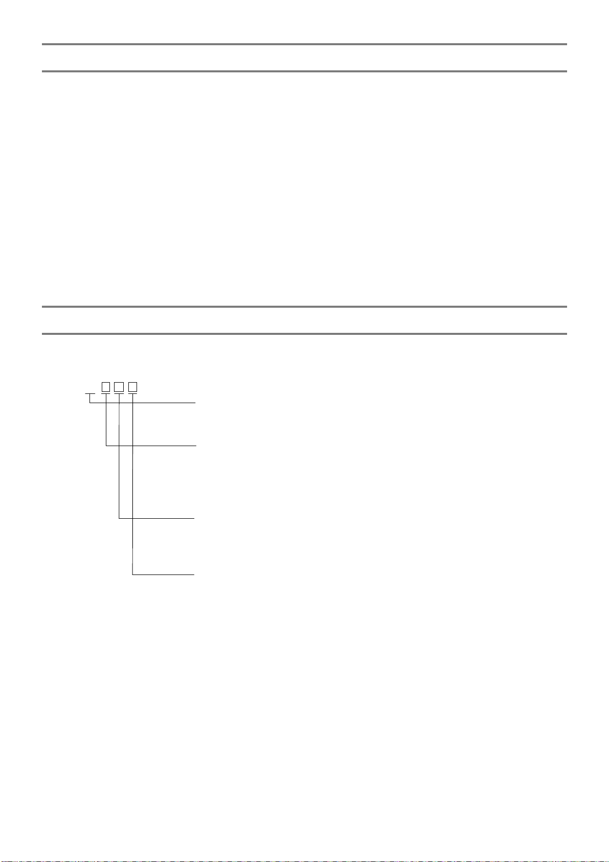
2. Model...............................................................1
2.1 Models.........................................................1
2.2 IR-CA series accessories models.................2
2.3 Standard measuring Range..........................2
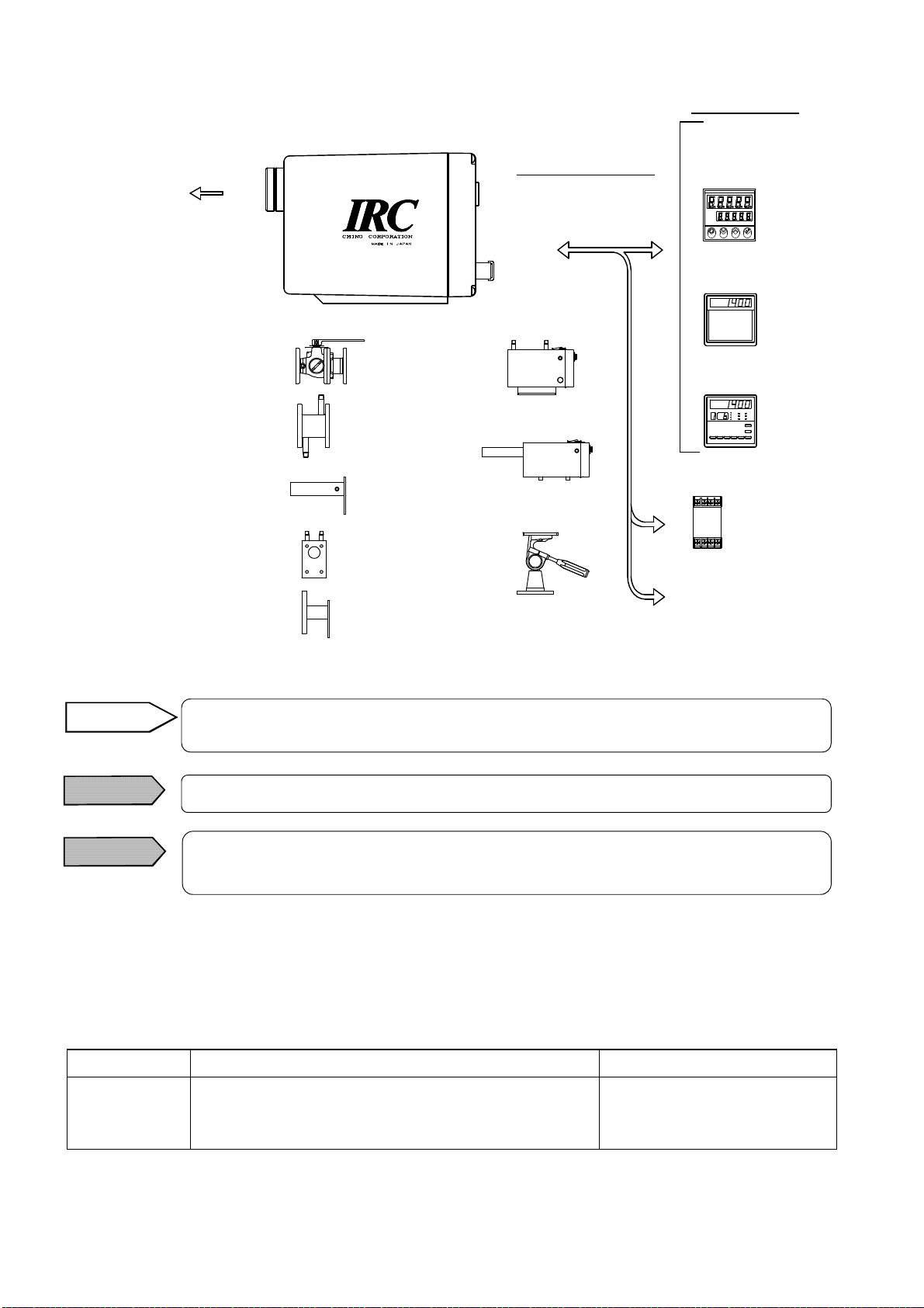
2.4 System configuration...................................3
2.5 Options ........................................................3
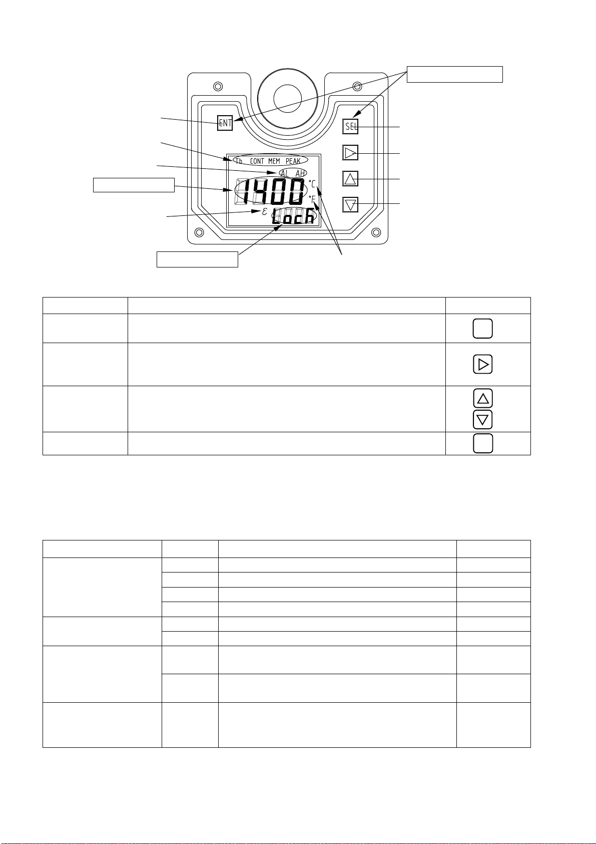
3. Names and functions of component parts........4
3.1 Overview.....................................................4
3.2 Function keys and digital display................5
3.2.1 Functions keys*1......................................5
3.2.2 Markers.....................................................5
4. Installation .......................................................6
4.1 Precautions in installation ...........................6
4.2 Installation...................................................6
4.3 Targeting......................................................7
4.3.1 Measuring distance and measuring
diameter.............7
4.3.2 Focusing of laser targeting function.........8
5 .Connections and wirings..................................9
5.1 Connections.................................................9
5.1.1 Connector connections
(For model IR-CAKC)......................9
5.1.1-1 Connection of the exclusive cable
IR-ZCRC ................9
5.1.2 Terminal wirings
(For model IR-CAKT)....................10
5.1.2-1 Wirings of the exclusive cable
IR-ZCRT................10
5.1.2-2 Wirings to power terminals.................10
5.1.2-3 Wirings to ground terminals................10
5.1.3 Wirings to receiving instruments............ 11
5.1.4 Connections to option + and option -
terminals..........11
6. Operation .......................................................12
6.1 Self-diagnostic function ............................12
6.2 Overflow/underflow..................................12
7. Maintenance and check..................................13
7.1 Periodical checking…. ..............................13
7.2 Trouble shooting........................................13
7.2.1 Measuring value not displayed or
displayed lower........13
7.2.2 Measuring value displayed higher..........13
7.2.3 Display fluctuated...................................13
8. Reference.......................................................14
8.1 Emissivity table.........................................14
8.1.1 Emissivity table (= 0.65µm)................14
8.1.2 Emissivity table (=8 to 11.5µm)..........15
9. General Specifications...................................16
9.1 Thermometer .............................................16
9.2 IR-CAK□□□ outside dimensions..............17
9.2.1 IR-CAKC(Connector type)...............17
9.2.2 IR-CAKT(Terminal type).................17
9.3 Accessories outside dimensions ................18
9.3.1 Protective case (Hard type) IR-ZCCH.18
9.3.1-1 IR-ZCCHC (Connector type)..............18
9.3.1-2 IR-ZCCHT (Terminal type) ................18
9.3.2 Protective case (Soft type) IR-ZCCS...19
9.3.2-1 IR-ZCCSC (Connector type) ..............19
9.3.2-2 IR-ZCCST (Terminal type).................19
9.3.3 Sealing window IR-ZW..................20
9.3.4 Water-cooling flange IR-VSW...............20
9.3.5 Air-purge hood IR-VAAPFX1................21
9.3.6 Water-cooling plate IR-ZCWC...............21
9.3.7 Flange installation plate IR-ZCAF.........22
9.3.8 Simple type universal head IR-ZMS......22
Note)
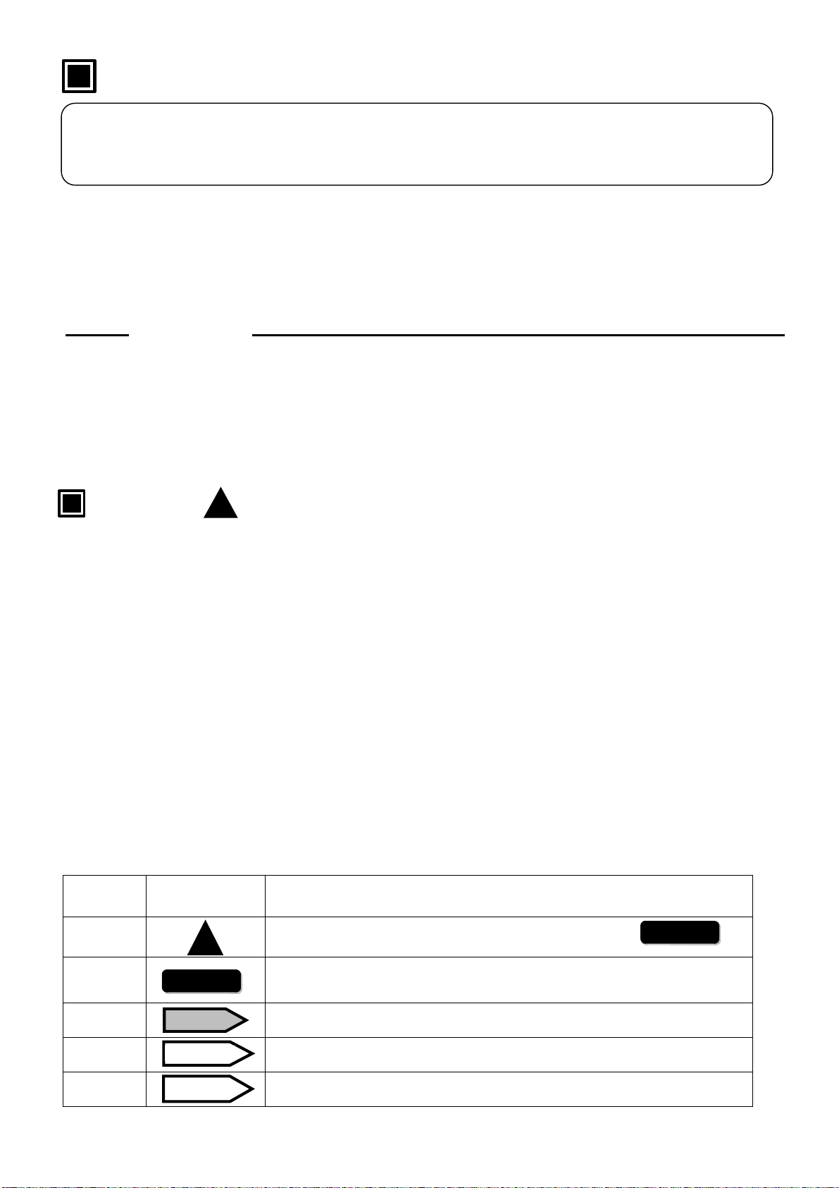
Make sure to read the items with the mark of the articles of are included.
!
Warning
!
!
!
!

INST.No.INE-551-P1
- C2 -
!
Request and notices
◆Request to the operator of the thermometer
This instruction manual describes the maintenance of the thermometer, too.
Keep this instruction manual with the thermometer.
If you have unclear points or need technical assistance, please contact your sales agent of
CHINO Corporation.
Notices
1. The information in this manual is subject to change without notice and does not represent a
commitment on the part of CHINO Corporation.
2. No part of this manual may be reproduced or transmitted in any form or by any means,
electronic or mechanical, including photocopying and recording, for any purpose other than
the purchaser's personal use without permission of CHINO Corporation.
3. CHINO Corporation shall not be liable for any operation results.
To use single color radiation thermometer fixed focus lens type (Model IR-CAK) correctly and safely,
please keep the following safety measures for the operation and storage of the thermometer.
1. Working conditions and environment
∙The working temperature range of the thermometer is 0 to 50 °C. (No dew condensation)
∙Do not use the thermometer in dusty places, etc. Remove the dust after using it.
∙Be careful not to give vibration or impact to the thermometer. Install the thermometer as far as
possible from an inductive oscillator or electric power line.
2. Storage
∙Do not store the thermometer in hot and humid places.
∙For failures of the thermometer, don’t overhaul it by yourself, and contact your sales agent of
CHINO Corporation.
3. Symbols in this instruction manual
The symbols shown below are used depending on important degrees for using the
thermometer safely and avoiding unexpected situations.
Important
degree Symbols Contents
1This symbol is attached to a title for the sentence with .
2
For avoiding dangerous accidents (may cause death or serious injury)
like as electrical shock, fires, or troubles/damages of the thermometer.
3For avoiding injury or in physical damage to the thermometer.
4Information that we suggest to read carefully.
5Information that you can use as a reference.
Preface
!
Warning
Warning
Caution
Remarks
Reference
This instruction manual is explaining only "Hardware volume" for using single color
radiation thermometer fixed focus lens type (Model IR-CAK) correctly and safely, read the
separate i
nstruction manual [IR
-
CAK
Software volume]
.

INST.No.INE-551-P1
- C3 -
Please use the thermometer correctly by keeping the following items.
In addition, please read this instruction manual carefully and keep it at the place where
you can access easily.
The mark indicates prohibited operations.
Warning (May cause death or serious injury)
Don’t operate the thermometer in places where combustible or volatile gas is
existed.
It is extremely dangerous to use the thermometer in such environment.
When connecting power to the power terminals, make
sure that all mains is
turned off to prevent an electric shock.
Don’t use the thermometer if it was broken, smoking or nasty smelling.
These
may cause fire. For such abnormal condition, turn off the power switch at once
and contact your sales agent of CHINO Corporation.
Laser may damage your eyes. Don’t stare into a laser beam. Make sure to target
the laser when you want to decide the center of the measuring object only and to
go off it after the center of the measuring object is decided.
Never take the thermometer apart or convert it.
These may cause trouble and danger.
Caution (May cause injury or physical damage)
Be careful not to give vibration or impact to the thermometer. Install the thermometer
by keeping it as far as possible from an inductive oscillator or electric power line.
Do not use the thermometer in dusty places, noisy places and static electricity places.
Do not wire the connection cable near a noise occurrence resource, relay drive line,
high frequency line and power line.
Do not bundle the connection cable with the line that noise is doubling, and do not
store it into the same duct.
Read the entire contents in this instruction manual to have the thermometer function
perfectly.
!
Warnings and Cautions
!
!
!
!
!
!
!
!
!
!

INST.No.INE-551-P1
- 1 -
1. Introduction
1.1 General
IR-CAK is single color radiation thermometer.
Converting functions enabling digital temperature display and parameter programming are built-in.
It is suitable for measuring especially a low-temperature region at high speed.
Also it is suited to measurement such as metal, by short measuring wavelength.
This thermometer is the high accuracy fixed focus type that adopted the front chop method.
And this thermometer has laser targeting function for targeting to the measuring objects.
The radiation energy collected through the objective lens is transmitted to the element is converted into an
electrical signal. The element output is digitally converted and processed through emissivity
compensation, linearizer and modulation. The standardized final output is 4 to 20mA DC. Functional keys
make programming or selection of emissivity, signal modulation and alarm function easy.
2 types of connection by terminals or a connector are available in this thermometer depending on a
connection cable. Various options and accessories are prepared for every kind of applications.
2. Model
2.1 Models
IR-CA K Type
K : Low temperature/Long wavelength
Measuring distance and measuring diameter
L : 20/1000mm
M : 10/ 500mm
N : 4/ 200mm
Z : Optional
Connections and wirings
C : Connector
T : Terminal
External input/output (Optional)
N : None
S : Communications interface RS-485 (Optional)

INST.No.INE-551-P1
- 2 -
2.2 IR-CA series accessories models
Accessories Model Remarks
Protective case(Hard type) IR-ZCCH□ C: Connector type T: Terminal type
Protective case(Soft type) IR-ZCCS□ C: Connector type T: Terminal type
Sealing window IR-ZW□ 0: Quartz glass 1:CaF22:BaF2
Water-cooling flange IR-VSW
Air-purge hood IR-VAAPFX1
Water-cooling plate IR-ZCWC
Flange installation plate IR-ZCAF
Simple type universal head IR-ZMS
2.3 Standard measuring Range
50 to 400ºC

INST.No.INE-551-P1
- 3 -
Accessories have many kinds of combinations for applications.
Refer to a separate instruction manual for each accessory.
2.4 System configuration
2.5 Options
The following options can be added this thermometer.
Confirm what kinds of options have been added to your thermometer referring to [2.1 Models].
Options Contents Reference
Communicatio
ns interface*
RS-485Transmission of measured data (One decimal
place)Transmission and also reception of parameter
programming.
Refer to the separate instruction
manual [IR-CAS]
Make sure to light the laser when you want to target a measurement area only and
to go off it after targeting.
Caution
Note: The laser light is radiated from the point marked with.
Caution
[Instruments]
[Accessorie
Note
External input/output
(option)
(Ref. [2.5 Options])
24VDC
power supply
Controller
Recorder
IR-CA
Sealing window
IR-ZW
Water
-
cooling flange
IR-VSW
Air
-
purge hood
IR-VAAPFX1
Water
-
cooling plate
IR-ZCWC
Flange installation plate
IR-ZCAF
Protective case
(Soft type)
IR
-
ZCCS
Simple type
universal head
IR
-
ZMS
Setting display unit with
power Supply IR-GZ
Connection cable
IR-ZCRC
[Instruments]
IR-ZCRT
or IR-ZCRL
Protective case
(Hard type)
IR
-
ZCC
H
Reference

INST.No.INE-551-P1
- 4 -
3. Names and functions of component parts
3.1 Overview
(1) Cover glass An optical glass for protecting the objective lens from scratches, smudges, etc.
(2) Screw hole for tripod A 1/4-20UNC screw hole for fixing a tripod or a simple type universal head
(3) Screw holes for installation
of thermometer M4 (depth 4mm) screw holes for installation of the thermometer
Use these screw holes for housing the thermometer in a protective case.
(4) Power lamp The red lamp lights when the power (24VDC) is supplied to the thermometer.
(5) Serial No. plate A plate for indication of Model No., Software version No., Serial No., and
Measuring range
For your inquiries, inform us of all items.
(6) Control panel cover The cover is for function keys and is fixed by M2.6 screws.
For programming parameters, remove it.
(7) Function keys 5 function keys for programming parameters
For programming, refer to [3.2.1 Function keys] and [6. Operation].
(8) Digital display panel
Main display: LCD 4 digits, Sub display: LCD 4 digits,
Status marker, Alarm status
Sub marker: Emissivity, Measuring unit: ºC or ºF
Refer to [3.2 Function keys and digital display] and [3.2.2 Markers].
(9) Terminal board
(Model IR-CAT only) Connect the thermometer by using the exclusive cable (IR-ZCRT) or the
recommended cable. (Ref. [5.1.2 Terminal wirings]).
(10) Connector
(Model IR-CAC only) Connect the thermometer by using the exclusive cable (IR-ZCRC or
IR-ZCRL). (Ref. [5.1.1 Connector connections ])
/
□
.
□□
EHTN
30 - 200
IA051E001
(2) Screw hole for tripod
[Serial No Label
for thermometer]
Model
Software
version No
Serial No
Measuring
range
[Terminal type] [Connector type]
(7)Function
keys
(9) Terminal board (10) Connector
(6) Control panel cover
(1) Cover glass (4) Power lamp
(5) Serial No. plate
(3) Screw holes for installation
of thermometer
(8) Digital display panel

INST.No.INE-551-P1
- 5 -
3.2 Function keys and digital display
3.2.1 Functions keys*1
Keys Functions Indications
(1): Select key Used to select a parameter menu in the operating mode or the
engineering mode.
(2): Next key Used to select a parameter in the parameter selection mode or
to shift a digit for numeric entries to the right in the parameters
programming mode.
(3): Up key
(4): Down key
Used to select a parameter in the parameter selection mode or
to scroll numeric characters in the parameters programming
mode.
(5): Entry key Used to store the selected or programmed parameter.
3.2.2 Markers
Main display*2: Displays the measured value in the measurement mode, or a parameter in the
parameter selection or programming mode.
Sub display*3: Displays the parameter menu selected by SEL key in the measurement mode, or a
parameter menu in the parameter selection or programming mode.
Names Markers Major functions Indications
(6): Main marker
Tb Not used “Tb”
CONT Not used “CONT”
MEM Not used “MEM”
PEAK Not used “PEAK”
(7): Status marker AL Will light when the low alarm is activated. “AL”
AH Will light when the high alarm is activated. “AH”
(8): Temperature unit C
Will light when a temperature is displayed
in Celsius. “C”
F
Will light when a temperature is displayed
in Fahrenheit. “F”
(9): Sub marker
Will light when the sub display shows
an emissivity.
(emissivity) is for single-color type. “”
SEL
ENT
(7) Status marker
(1) Select key
(2) Next key
(3) Up key
(4) Down key
(5) Entry key
(6) Main marker
(8) Temperature unit
(9) Sub marker
Functions keys*1
Main display*2
Sub display*3

INST.No.INE-551-P1
- 6 -
4. Installation
4.1 Precautions in installation
This IR-CA series radiation thermometer is a sensitive instrument.
Install it by referring to the following cautions.
4.2 Installation
Install the thermometer to a tripod, universal
head, protection case, or mounting plate etc., by
using screw holes for tripod (1/4-20UNC) or
screw holes for installation (4-M4) at the bottom
side.
Please read the operation manual for an
accessory when instilling it by using the
exclusive accessories.
●
Vibration and impacts
Vibration or impacts reduces the liability of the thermometer and causes an
unstable measurement by the targeting shake to a measuring surface.
If you install the thermometer in the place where vibration or impacts exist, its
caref
ul periodic inspection is requested.
Caution
●
Induction
The thermometer is designed for anti-induction but install it as far as possible
from an induction heating generator and power line distance factor.
: Outer circle inside
Caution
●
Optical path
Select a place for installation of the thermometer, where water-drops, dust, smoke,
steam, etc. would not enter between the thermometer and a measuring surface.
If such place cannot be selected and the affection by existence of such substances
cannot be ignored, blowing-out of such substance with air-purge is necessary.
Caution
●
Disturbance
s
to
make
indicat
ion
of measured value
higher
Select a place for installation of the thermometer, where sunlight, light of
incandescent lamp, flame, heat radiation from a high temperature substance,
etc. is not reflected to the measured surface and the cover glass of the
thermometer. When such light is reflected, higher temperature than the exact
one will be indicated. (The affect by such reflection will be great for the
measurement of low temperature.) If such place cannot be selected, shade the
thermometer or take similar precautionary measures.
Caution
Don
’
t use the thermometer in the following places.
1) Dusty place or a corrosive gas atmosphere.
2) Noisy and static electricity
3) Places where the ambient temperature is higher than 50°C or lower than 0°C.
4) Places where the ambient temperature changes abruptly, or high humid places.
5) Places where there are mechanical vibrations and impacts.
6) Places where combustible or volatile gas is existed.
Caution
●
Working
te
mperature
The working temperature of the thermometer is 0 to 50ºC. If the ambient
temperature is high or if the temperature of the thermometer exceeds the
maximum working temperature by reflection from a high temperature
substance, etc., water-cooling of the thermometer is absolutely necessary.
When the temperature of the thermometer does not exceed but closely reaches to
the maximum working temperature, water-cooling of the thermometer is
recommended for maintaining of the reliability of the thermometer.
Caution
Screw hole for tripod
1/4-20 UNC (depth 4)
(Refer to [3. Names and functions of component parts].)
Screw holes for installation
4-M4 (depth 4)
45 70
80
30
Unit: mm

INST.No.INE-551-P1
- 7 -
4.3 Targeting
4.3.1 Measuring distance and measuring diameter
The relation of the measuring distance and the measuring diameter is defined by the distance factor as
shown in the following table and figure.
[Measuring distance and measuring diameter table]
Models Measuring distance and the measuring diameter
IR-CAKL 20/1000mm
IR-CAKM 10/500mm
IR-CAKN 4/200mm
φ15
φ20
φ55
2000 1000 0
IR-CA □L□□ IR-CA□M□□
φ15
φ35 φ10
1000 500 0
IR-CA □N□□
φ15
φ4
200
400 0
φ35
IR-CA □P□□
φ15
φ19 φ2
200 100 0
Unit: mm
Considering the dislocation of the optical axis, take the measuring area more than 1.5
times the measuring diameter.
Reference
For the installation of the thermometer with a protective case, house the
thermometer to the protective case after adjusting the focus of the thermometer.
Caution
IR
-
CAKL□□
IR
-
CAKN□□
IR
-
CAKM□□

INST.No.INE-551-P1
- 8 -
When the laser targeting is activated, the laser light is radiated from the place
marked with (*). Make sure not to stare into a beam.
4.3.2 Focusing of laser targeting function
For the laser targeting, focus a measuring object by the procedure shown below after connections
(Ref. [5. Connections and wirings]).
(1) Open the control panel cover.
(2) Measurement starts with the display of the measurement mode
screen with a temperature value displayed in the main display part
as shown right.
(3) To activate the laser targeting, press SEL and keys
simultaneously for 2 seconds in the measurement mode
screen until “LASr” appears in the sub display.
(4) To stop the laser targeting, press SEL and keys simultaneously
for 2 seconds in the condition that “LASr” is displayed in the sub
display.
(5) “LASr” will disappear and the screen will return to the
measurement mode screen.
Tb CONT MEM PEAK
AL AH
C
F
ε
[Measurement mode]
During the laser targeting,
“
LASr
”
is displayed
in the sub display as shown in the right figure.
Place the thermometer to make the laser light
target the center of a measuring object.
Reference
1. Make sure to target the laser when you want to decide the center of the
measuring object only and to keep on following the above procedure when
you exactly target the laser.
2. Any adjustment or procedure other than specified here makes you expose in
dangerous laser radiation.
Caution
Make sure to target the laser when you want to decide the center of the measuring
object only and to go off it after the center of the measuring object is decided.
Caution
Tb CONT MEM PEAK
AL AH
C
F
ε
[ Laser targeting ]
Main displaySub display
Laser light is
radiated here. (*)
Alarm label
!
Laser may damage your eyes.
Don
’
t stare into a laser beam.
Warning
!
Warning
!

INST.No.INE-551-P1
- 9 -
5 .Connections and wirings
5.1 Connections
5.1.1 Connector connections (For model IR-CAKC)
5.1.1-1 Connection of the exclusive cable IR-ZCRC
The connections are completed by simply connecting the connector of the cable (IR-ZCRC) to the
connector placed at the rear side of the thermometer.
(1) For the connection, align the slit in the connector of the cable and the key position in the connector of
the thermometer, and firmly insert the cable connector, and then turn the coupling ring clockwise until
it is locked.
(2) For the disconnection, turn the coupling ring counterclockwise for releasing its locked status, and pull
the connector of the cable forward.
(Refer to [3. Names and functions of component parts].)
Pin No.
1 +
2 -
3 + (SA)
4 - (SB)
5 +
6 -
7
8―― Ground
Temperature output
4 to 20mA DC
Input/output for
options
24V DC power
(Empty terminal)
Key position Coupling ring
Thermometer (IR-CA)
side
Cable side
Slit
!
Make sure to turn off the power supply for preventing an electric shock when
connecting and wiring.
Warning
!

INST.No.INE-551-P1
- 10 -
5.1.2 Terminal wirings (For model IR-CAKT)
5.1.2-1 Wirings of the exclusive cable IR-ZCRT
Connect the exclusive cable (IR-ZCRT) or a commercially available cable to the terminal board (Terminal
screw size: M3) placed at the rear side of the thermometer.
5.1.2-2 Wirings to power terminals
5.1.2-3 Wirings to ground terminals
Provide a low impedance earth ground (lower than 100Ω) connection to the
ground terminal.
Caution
Cable specifications
Shielded twisted pair cable
・Nominal sectional area: 0.5mm2
・Recommended cable: Sunlight SX
3P x 0.5mm2
Ground
+ -
Temperature
output
4 to 20mA DC
+ -
24V DC
power supply
+ -
Input/output for
RS-485(Optional)
(SA) (SB)
!
Make sure to turn off the power supply for preventing an electric shock when
connecting and wiring.
Warning
!

INST.No.INE-551-P1
- 11 -
5.1.3 Wirings to receiving instruments
Connection cable detailed figure for receiving instrument side
5.1.4 Connections to option + and option - terminals
For IR-CAS (RS-485 communications): Connect to SA and SB terminals.
For IR-CAS, refer to the separate instruction manual
[IR-CA Communications Instruction Manual].
Caution
The current output is 4 to 20mA DC and isolated.
Connect the signal terminals and a receiving instrument.
The contact output is the open collector output (photo-coupler).
Use a receiving instrument under the ratings (30V, 50mA).
Reference
Signal line for
options
Power supply line
Ground wire
Black
SIGNA
L
+
SIGNAL
–
OPTION
+
OPTION
–
POWER
+
POWER
–
Gray
EARTH
Temperature
output
4 to 20mA DC
Markers
Line color
Bl
ack / White
Green
Green / White
Red
Red / White

INST.No.INE-551-P1
- 12 -
6. Operation
6.1 Self-diagnostic function
This self-diagnosis function is built-in. An error No will be displayed on abnormal conditions.
Main display Contents Countermeasure Output
(Note*)
Ambient temperature
is abnormal Use the thermometer in the environment
from 0 to 50ºC. Yes
Motor rotation is abnormal Built-in motor is abnormal. Return to
factory to us, and please order the repair
Analog output is about 2mA DC. Yes
E2PROM abnormal
(Writing and reading
impossible) Return to factory to us. Yes
Analog output correction
data abnormal (Same data
before correction existed.) Check the data before correction again. No
Zero/span adjustment
abnormal
(Data at zero > data at span)Adjust zero and span again. No
Remote emissivity
programming exceeding the
programmable range
Program to 0.001 when the emissivity
programming value is overshooting from
the minimum value and 1.999when it is
overshooting from the maximum value.
No
Automatic emissivity
calculation exceeding the
programmable range
Program the emissivity value to1.000.
However, this programming is not stored. No
(Note*)
6.2 Overflow/underflow
● “oFL” is displayed when the measured temperature is higher than (420ºC).
● “uFL” is displayed when the measured temperature is lower than ( – 5ºC).
On the items with “Yes” in the output column, the contact signal for the abnormal
condition is outputted from the contact output terminals (OFF at abnormal condition).
This output is available when “Self-diagnostic abnormal” is selected in [Contacts output
item selection] in the engineering mode.
(Refer to the separate instruction manual [IR-CA series Software volume])
[Overflow] [Underflow]

INST.No.INE-551-P1
- 13 -
7. Maintenance and check
7.1 Periodical checking…Check the followings periodically or if required.
•Lens: Check the objective lens for dust or dirty.
If dirt is present, remove it with a blower for camera lens. If the dirt cannot be removed with the
blower, wipe the lens gently with cotton ball soaked in alcohol.
•Connections and wirings: Check all connections and wirings.
7.2 Trouble shooting
7.2.1 Measuring value not displayed or displayed lower
Checking item Countermeasure
1) Is Er03' lighted' the error display of motor turn
abnormality? Built-in motor is abnormal. Return to factory to us,
and please order the repair
2) The power voltage is not in the allowable range. Supply the power with the correct voltage.
3) The Connection cable is not connected firmly. For the disconnection of the cable, replace it.
4) The view field is interfered.
Make the view field not interfered by referring t o
[4.3 Targeting].
5) The measured temperature is lower than the
minimum value of the measuring range.
It is necessary to use a thermometer with the
measuring range covering the measured
temperature.
6) The emissivity value programmed is too high. Program the emissivity value by referring to
[Emissivity programming]. (*)
7) The atmosphere temperature is low, the optic system
is doing no dew . It uses it in the place where does not do dew.
7.2.2 Measuring value displayed higher
Checking items Countermeasure
1) The measured temperature is higher than the
maximum value of the measuring range.
It is necessary to use a thermometer with the
measuring range covering the measured
temperature.
2) The emissivity value programmed is too low. Program the emissivity value by referring to
[Emissivity programming]. (*)
3) The heat radiation of the high temperature is shining
to the measurement face or thermometer from the
outside.
Heat is prevented with the board that does not pass
the change or light of the place
7.2.3 Display fluctuated
Checking items Countermeasure
1) The radiation thermometer is not fixed firmly or
vibrated. Fix the radiation thermometer firmly and install it
in a place not vibrated.
2) The connector and terminal are not connected
firmly. Connect the connector and terminal firmly.
3) The power voltage is not in the allowable rang Supply the power with the correct voltage.
4) The view field is interfered by steam. Purge the steam by air.
5) The measured temperature is fluctuated exactly. Program the emissivity value and the modulation
degree by referring to the following paragraphs.
[Emissivity programming](*) [Automatic
emissivity calculation] (*)[Signal modulation mode
selection] (*)[Modulation degree programming] (*)
6) Emissivity value is changeabling.
(*): Refer to separate instruction manual [IR-CA series Software volume].
1. Do not disassemble this thermometer. If you disassemble, it causes the obstacle to
your eye because laser function is built-in.
2. Make sure to target the laser when you want to decide the center of the measuring
object only and to keep on following the above procedure when you exactly target the
laser. Any adjustment or procedure other than specified here makes you expose in
dangerous laser radiation.
Warning
!
!

INST.No.INE-551-P1
- 14 -
8. Reference
8.1 Emissivity table
The emissivity are values determined by the material of object, profile of its surface, surface roughness,
oxidized or not, measuring temperature, measuring wavelength and other factors.
They are represented by the thermal radiation ratio "" when a black body furnace at the same
temperature is measured in the same wavelength band.
The emissivity "" is generally known by a value at the wavelength of 0.65µm when an optical pyrometer
is used. The emissivity changes according to the above factors even in case of the same material. Please
use the following table as a reference.
8.1.1 Emissivity table (= 0.65µm)
Metal Emissivity Oxide Emissivity
Solid Liquid
Zinc 0.42 ―Alumel(*)0.87
Alumel 0.37 ―Chromel(*)0.87
Aluminum 0.17 0.12 Constantan(*)0.84
Antimony 0.32 ―Ceramics 0.25 to 0.5
Iridium 0.30 ―Cast iron(*)0.70
Yttrium 0.35 0.35 55Fe. 37.5Cr. 7.5Al(*)0.78
Uranium 0.54 0.34 70Fe. 23Cr. 5Al. 2Co(*)0.75
Gold 0.14 0.22 80Ni. 20Cr(*)0.90
Silver 0.07 0.07 60Ni. 24Fe. 16Cr(*)0.83
Chromium 0.34 0.39 Stainless steel(*)0.85
Chromel P 0.35 ―Aluminum oxide 0.22 to 0.4
Cobalt 0.36 0.37 Yttrium oxide 0.60
Constantan 0.35 ―Uranium oxide 0.30
Zirconium 0.32 0.30 Cobalt oxide 0.75
Mercury ―0.23 Columbium oxide 0.55 to 0.71
Tin 0.18 ―Zirconium oxide 0.18 to 0.43
Carbon 0.8 to 0.9 ―Tin oxide 0.32 to 0.60
Tungsten 0.43 ―Cerium oxide 0.58 to 0.82
Tantalum 0.49 ―Titanium oxide 0.50
Cast iron 0.37 0.40 Iron oxide 0.63 to 0.98
Titanium 0.63 0.65 Copper oxide 0.60 to 0.80
Iron 0.35 0.37 Thorium oxide 0.20 to 0.57
Copper 0.10 0.15 Vanadium oxide 0.70
Thorium 0.54 0.34 Beryllium oxide 0.07 to 0.37
Nickel 0.36 0.37 Magnesium oxide 0.10 to 0.43
80Ni /20Cr 0.35 ―
60Ni / 024Fe / 16Cr 0.36 ―(*) : Oxidized on surfaces
Platinum 0.30 0.38
90Pt / 10Rh 0.27 ―
Palladium 0.33 0.38
Vanadium 0.35 0.35
Bismuth 0.29 ―
Beryllium 0.61 0.61
Manganese 0.59 0.59
Molybdenum 0.37 0.40
Rhodium 0.24 0.30

INST.No.INE-551-P1
- 15 -
8.1.2 Emissivity table (=8 to 11.5µm)
Metal Emissivity
Aluminum 0.025 to 0.35
Chrome 0.07 to 0.85
Cobalt 0.35 to 0.44
Copper 0.03 to 0.80
Gold 0.02
Steel plate 0.10 to 0.80
Lead 0.13 to 0.65
Magnesium 0.07 to 0.0.75
Molybdenum 0.10 to 0.80
Nickel 0.04 to 0.85
Palladium 0.05
Platinum 0.07
Rhodium 0.05
Silver 0.02 to 0.12
Tantalum 0.08 to 0.75
Tin 0.06 to 0.60
Titanium 0.15 to 0.60
Tungsten 0.06
Zinc 0.04 to 0.30
Alloy Emissivity
Brass
0.03 to 0.60
Chromel-Alumel 0.03 to 0.80
Constantan, Manganin 0.05 to 0.35
Inconel 0.10 to 0.85
Monel
0.10 to 0.70
Nichrome 0.20 to 0.85
Ceramics Emissivity
Alumina ceramics 0.60
Red brick 0.90
White brick 0.80
Silicon brick 0.80
Sillimanite brick 0.60
Ceramics 0.90
Magnesite 0.60
Other Emissivity
Asbestos 0.90
Asphalt 0.85
Carbon 0.85
Graphite 0.80
Soot 0.95
Cement, Concrete 0.70
Cloth 0.80
Use the above tables as a reference.
Reference
Table of contents
Other Chino Thermometer manuals

Chino
Chino IR-BZ Series User manual

Chino
Chino IR-CA series User manual

Chino
Chino IR-AH Series User manual

Chino
Chino IR-FA Series User manual

Chino
Chino IR-CZ Series User manual

Chino
Chino IR-E Series User manual

Chino
Chino IR-H Series User manual

Chino
Chino TP-S Easy Thermo User manual

Chino
Chino IR-SA Series User manual

Chino
Chino IR-BAT Series User manual