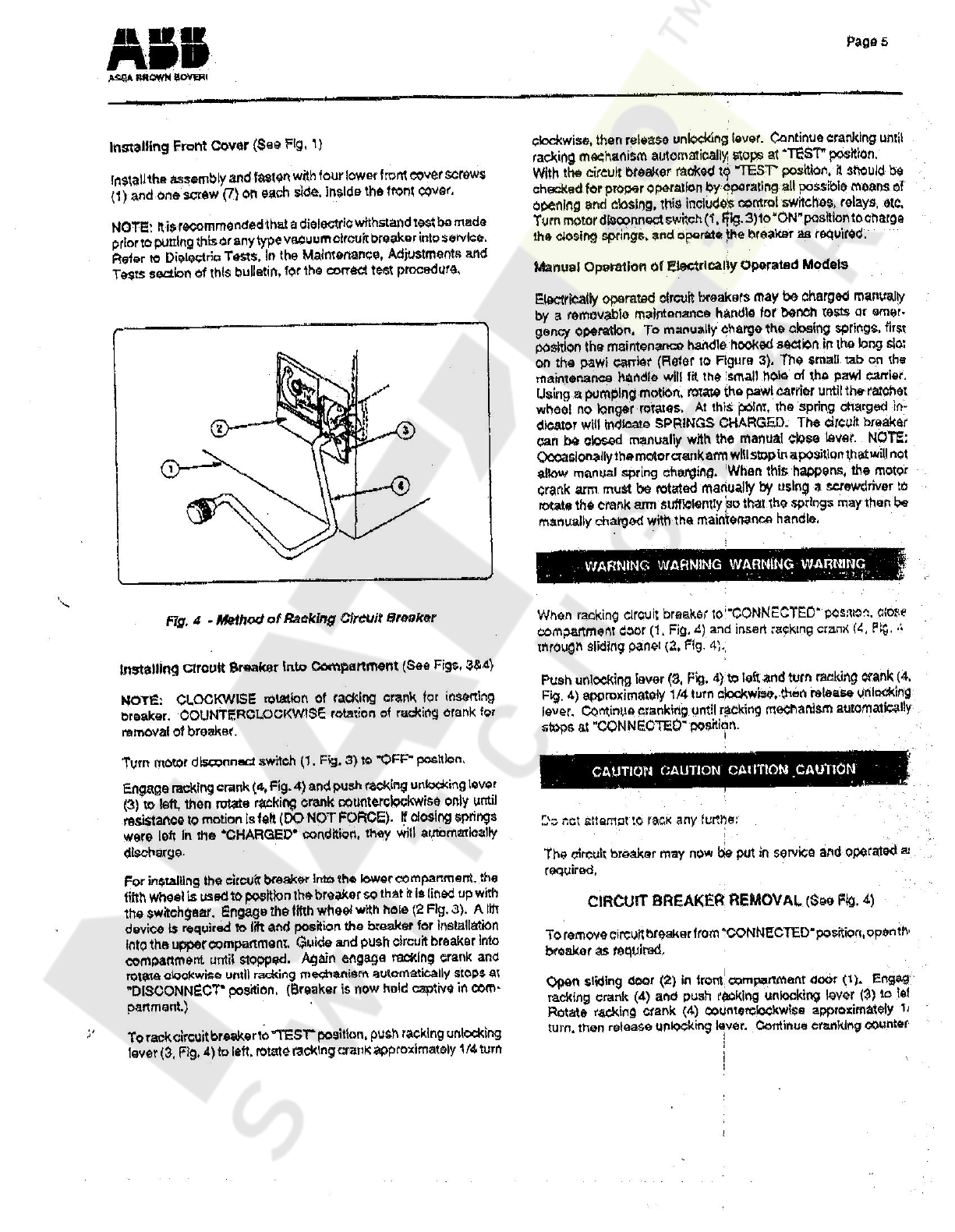
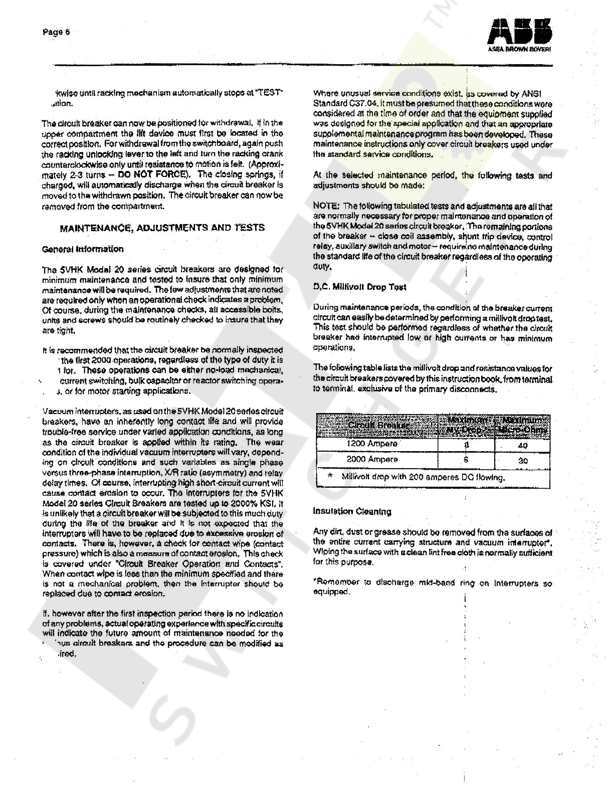
ABB 5VHK 250 Installation and operating instructions
Other ABB Circuit Breaker manuals

ABB
ABB Emax Series User manual

ABB
ABB SF6 LTB 245E1 BLG 1002A User manual

ABB
ABB HD4/R Quick guide

ABB
ABB SACE Tmax XT User manual

ABB
ABB TMAX MOE User manual

ABB
ABB SACE Emax 2 User manual

ABB
ABB SMISSLINE TP 2CCC451032M0109 User manual

ABB
ABB SACE Emax 2 User manual

ABB
ABB SACE Tmax XT5 User manual

ABB
ABB EMAX E2.2 Series Service manual

ABB
ABB SACE Emax 2 E2.2 User guide

ABB
ABB GE Power Break II GEH6271 User manual

ABB
ABB Vmax User manual

ABB
ABB S4 User manual

ABB
ABB VM1 Quick guide

ABB
ABB Tmax RC221 User manual

ABB
ABB SACE Emax 2 E2.2 User manual

ABB
ABB SACE Tmax T6 User manual

ABB
ABB SACE Emax 2 E2.2 User manual

ABB
ABB SMISSLINETP FS401 Service manual


Popular Circuit Breaker manuals by other brands


Eaton
Eaton Power Defense PDG2 Instruction leaflet

Bticino
Bticino L4412CM2 quick start guide

Eaton
Eaton S-T0 Instruction leaflet

OEZ
OEZ 3VA9-RS-4VBH1 Installation, service and maintenance instructions

Siemens
Siemens PSR Instructions, Installation, Operation, Maintenance

Rockwell Automation
Rockwell Automation Allen-Bradley 140G-G manual