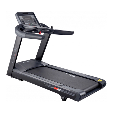
CIRCLE FITNESS M8 User manual

1
Ver.2017/09/01


M8 –Owner’s Manual
Page2
TABLE OF CONTENTS
INTRODUCTION ________________________________________________________________ 3
1. SAFETY _____________________________________________________________________ 4
1. 1 Important Safety Notes_________________________________________________________________ 4
1. 2 Grounding Instructions _________________________________________________________________ 6
1.3 Electrical Recommendations ____________________________________________________________ 6
1.4 Emergency Stop Key & Emergency Stop Button ___________________________________________ 7
2. ASSEMBLY __________________________________________________________________ 8
2.1 Specifications __________________________________________________________________________ 8
2.2 Machine Overview ______________________________________________________________________ 9
2.3 Location and Transportation ___________________________________________________________ 10
2.4 Unpacking ____________________________________________________________________________ 11
2.5 Assembly Procedures__________________________________________________________________ 15
2.6 Adjustments __________________________________________________________________________ 22
2.7 Engineering Settings: FACTORY SETTINGS ______________________________________________ 24
2.8 Test Operation ________________________________________________________________________ 25
3. OPERATION ________________________________________________________________ 26
3.1 Heart Rate System_____________________________________________________________________ 26
3.2 Emergency Stop _______________________________________________________________________ 27
3.3 Quick Shift ____________________________________________________________________________ 27
3.4 Body Position _________________________________________________________________________ 27
4. CONSOLE OVERVIEW ________________________________________________________ 28
4.1 Identifying the Parts of the Console _____________________________________________________ 28
4.2 Program Profiles and Operation ________________________________________________________ 30
5. ENGINEERING MODE ________________________________________________________ 41
5.1 ENGINEERING MODE 1: Information ____________________________________________________ 41
5.2 ENGINEERING MODE 2 : Settings _______________________________________________________ 42
5.3 ENGINEERING MODE 3 : Lock Function__________________________________________________ 43
6. MAINTENANCE _____________________________________________________________ 44
6.1 Preventive Maintenance Tips ___________________________________________________________ 44
6.2 Preventive Maintenance Schedule ______________________________________________________ 44
6.3 Troubleshooting the Treadmill__________________________________________________________ 45
6.4 Error Message and Solutions ___________________________________________________________ 46
6.5 How to Adjust and Tension the Running _________________________________________________ 48
6.6 Running Belt and Running Deck Service Schedule ________________________________________ 48
7. CUSTOMER SERVICE ________________________________________________________ 49
7.1 Warranty Claim Process________________________________________________________________ 49
8. APPENDIX _________________________________________________________________ 50
8.1 Reference Tables of the TEST Program _________________________________________________ 50
Version: 20190201_V001

M8 –Owner’s Manual
Page 3
INTRODUCTION
Dear Customer,
Thank you for purchasing this product.
This Owner’s Manual will guide you through the setup procedures and outline the key
features. Please keep it handy for future reference.
This product has been designed and manufactured for studio use, and even though we go
to great efforts to ensure the quality of each product, occasional errors, and/or omissions
do occur. In any event, should you find this product to be defective in any way, or to be
missing parts, please contact us.
No.12, 6th Road, Industrial Park,Taichung, Taiwan
Tel: +886-4-2359-1000
Fax: +886-4-3505-5801
Email: [email protected]
Website: http://www.circlefitness.com/

M8 –Owner’s Manual
Page4
1. SAFETY
1. 1 Important Safety Notes
IMPORTANT: Please read all instructions and warnings before assembly and operation.
To assure the correct use of the product, basic safety measures should always be
followed including the warnings and cautions listed in this Owner’s Manual.
IMPORTANT: It is essential that this equipment is used only indoors, in a climate
controlled room.
WARNING: Only one person at a time should use this equipment. If dizziness, nausea,
chest pains, or any other abnormal symptoms are experienced while using, then please
stop the workout at once.
WARNING: Always use this equipment on a clear and level surface. Do NOT use outdoors
or near water.
WARNING: Do NOT insert any object into any openings.
WARNING: Do NOT wear loose clothing or jewelry. This equipment contains moving parts.
Do NOT put fingers or other objects into the moving parts.
WARNING: Before using this equipment to exercise, always do stretching exercises first, in
order to properly warm up.
WARNING: It’s recommended to replace defective components immediately and keep this
equipment out of use until repairs have been completed by a professional service
technician.
WARNING: This equipment is designed for adults. Close supervision is necessary if the
equipment is used by children or near children. This also applies to disabled persons.
SAFETY SYMBOLS USED IN THIS OWNER’S MANUAL
WARNING
Indicates a potentially hazardous situation which, if not avoided, could
result in death or serious injury.
CAUTION
Indicates a potentially hazardous situation which, if not avoided, may
result in minor or moderate injury to the user or patient or damage to the
equipment or other property.
DANGER
Indicates a high probability that death, severe bodily injury or major
property damage could result.

M8 –Owner’s Manual
Page 5
1. 1 Important Safety Notes (Continued)
WARNING: Please consult your physician before starting a workout or a training program.
Its best to have your doctor review your training and diet programs first so that he can
advise the best workout routine for you.
WARNING: Make sure all Screws and nuts are securely tightened before operating this
equipment. Periodic maintenance is required on all exercise equipment to keep it in good
condition.
WARNING: Incorrect/excessive training can cause health injuries. Stop using the
equipment when feeling uncomfortable.
WARNING: Turn OFF the power switch when the equipment is not in use.
WARNING: If the power cord is damaged, it must be replaced by the manufacturer or its
service agent or a similarly qualified person to avoid any potential hazard.
SAVE THESE INSTRUCTIONS FOR FUTURE REFERENCE

M8 –Owner’s Manual
Page6
1. 2 Grounding Instructions
This equipment must be grounded. If it should malfunction or break down, grounding
provides a path of least resistance for electric current to reduce the risk of electric shock.
This equipment is equipped with a cord having an equipment-grounding conductor and a
grounding plug. The plug must be plugged into an appropriate outlet that is properly
installed and grounded in accordance with all local codes and ordinances.
DANGER: Improper connection of this equipment-grounding conductor can result in a risk
of electric shock. Check with a qualified electrician or service person if you are in doubt as
to whether the treadmill is properly grounded. Do NOT modify the plug provided with the
treadmill. If it doesn’t fit the outlet, get a proper outlet installed by a qualified technician.
1.3 Electrical Recommendations
Important Voltage Information
Before plugging the power cord into an
electrical outlet, verify that the voltage
requirements for your area match the voltage
of the treadmill that you have received. The
power requirements for the treadmill include
a grounded, dedicated circuit, rated for one
of the following figure.
See the serial number decal for the exact
voltage requirements of your treadmill.
The power requirements for the treadmill include a grounded, dedicated circuit, rated for
one of the following:
1) 115 VAC 5%, 60 Hz, 20 amps
2) 208/220 VAC, 60 Hz, 15 amps
3) 230 VAC 5%, 50 Hz, 15 amps
WARNING: Do NOT attempt to use this equipment with a voltage adapter. Do NOT attempt
to use this equipment with an extension cord.
115V
NEMA 5-20
EURO PLUG
CEE 7/7
208-220V
NEMA 6-15
TXXXXXXXXX
Voltage requirement

M8 –Owner’s Manual
Page 7
1.4 Emergency Stop Key & Emergency Stop Button
Emergency Stop Key
The Emergency Stop Key is to prevent user’s
injuries from falling down due to lack of
familiarity with the speed or usage of the
treadmill. Please always clip the Emergency Stop
Key to prevent or minimize accidents.
The Emergency Stop Key must be attached at
waist level before your workout. (Fig 1.4-1)
Fig 1.4-1
WARNING: Always attach the Emergency Stop Key to your clothing during your workout.
When you use the machine, only remove the Emergency Stop Key in an emergency.
WARNING: When the key is removed while the machine is in operation, it will stop quickly,
which could cause the loss of balance and possible injury.
Emergency Stop Button
This equipment is equipped with an Emergency
Stop Button (Fig 1.4-2), it’s allows the user an
additional safety feature in case of emergency.
Upon pushing the button the treadmill will stop.
Fig 1.4-2
Push
Emergency Stop Key

M8 –Owner’s Manual
Page8
2. ASSEMBLY
2.1 Specifications
M8
Display Type
6 LED + 8 x 32 Dot-Matrix +Goal Bar
Display Feedback
Time, Distance, Heart Rate, Calories, Speed, Incline
Programs
Manual, 5 Preset Program, 3 Goal, 4HRC, 7 Physical
Test, Customize
Quick Speed
5 Keys
Quick Incline
5 Keys
Running Belt
(L)153 x (W) 58 cm / (L) 60”x (W) 23’’
Roller
90 mm (3.5’’)
Speed
0.5-25 km/ 0.3-15.5 mph
Incline
1-16% (Levels)
Motor (HP)
4.0 HP (Continuous) / 6.0 HP (Treadmill Duty)
Motor Control
Standard
Fan
AC Inverter
Quick Shift
Standard
Hand Pulse
Standard
Heart Rate Receiver
Standard
Chest Belt
Optional
Power Requirement
110Vac/220Vac ±20%, 20A, 50-60Hz
Diameters (L x W x H) (approx.)
(L) 217 x (W) 94 x (H) 153 cm /
(L) 86 x (W) 37 x (H) 61 inches
Max. User Weight
182 kgs / 400 lbs

M8 –Owner’s Manual
Page 9
2.2 Machine Overview
Power Cord Inlet
Front Transport Wheel
Adjustable Fan
Console Set
Emergency Stop Button & Key
Quick Shift
Console Mast
Bottle Holder
Handlebar
Heart Rate Handlebar
Running Belt
Motor Cover
Power Switch
Front Transport Wheel

M8 –Owner’s Manual
Page10
2.3 Location and Transportation
Location
Place the equipment on a level surface. Do NOT place it in any area that will block any
vents or air openings. This equipment should not be located in a garage, covered patio,
near water or outdoors.
Minimum clearance is 19.7 inches (0.5 meters) on the sides of the equipment and 78.7
inches (2.0 meters) behind the equipment. (Fig 2.3-1)
Fig 2.3-1
Transportation
WARNING: Be sure the equipment is unplugged before moving.
To move the equipment, carefully lift the rear end by pushing down on the 2 front transport
wheels (Fig 2.3-2). Carefully steer the equipment to another location.
Fig 2.3-2
IMPORTANT: Be careful when moving this equipment, as it is heavy and awkward. If you
do not feel comfortable moving this equipment by yourself, please get help.
NOTE: The transport wheels are designed for indoor use only and should not be used to
move this equipment over rough surfaces such as concrete or asphalt.

M8 –Owner’s Manual
Page 11
2.4 Unpacking
To unpack the treadmill, please the following steps:
1. Carefully remove all staples from the carton.
2. Open the Carton 1 and remove the packing materials to take out the Console Set. (Fig
2.4-1)
Fig 2.4-1
3. Open the Carton 2 and remove the upper cardboard piece. (Fig 2.4-2)
Fig 2.4-2
3. Remove all parts from the Carton 2 and card board inserts.
4. Set the all the parts down near the spot where you plan to install the equipment.
5. With the help of at least one other person, remove all the packing materials and place
the main body assembly on a level flat surface.
Carton 2
Carton 1

M8 –Owner’s Manual
Page12
2.4 Unpacking (Continued)
Please verify that you have parts as per the list shown below:
NOTE: Make sure that Serial Number on Carton 1 matches that on Carton 2.
Carton 2
□
5Main Body
□
6Hardware Kit & Tools
(Refer to chapter 2.4.1 &
2.4.2)
□
4Right/ Left
Leveling Pad
Cover
□
1Console Set
□
2Right/ Left Console Mast
□
3Right/ Left
Console Handlebar
Carton 1

M8 –Owner’s Manual
Page 13
2.4.1 Hardware Kit
Please verify the hardware kit list as shown below:
STEP 2
STEP 3
(1) M8 x 20mm Screws (8 PCS)
(2) M8 Lock Washers (8 PCS)
(3) M8 Flat Washers (8 PCS)
(for Console Mast Set)
(1) M8 x 15mm Screws (6 PCS)
(2) M8 Flat Washers (6 PCS)
(for Console Mast Set & Console)
STEP 6
STEP 7
(1) M8 x 25mm Screws (4 PCS)
(2) M8 Flat Washers (4 PCS)
(for Handlebar)
(1) M3 x 12mm (1 PC)
(for Power Cord Locker)

M8 –Owner’s Manual
Page14
2.4.2 Tools
Please verify the tools list as shown below:
Allen Wrench (5mm)
Allen Wrench (6mm)
T-handle Allen Wrench
Power Cord Locker
Power Cord
Owner’s Manual

M8 –Owner’s Manual
Page 15
2.5 Assembly Procedures
STEP 1:
Remove the Motor Cover.
Unscrew the Motor Cover Screws #1 with the
provided 5mm Allen Wrench until they flush
with the lower edge of the Motor Cover #2
(Fig 2.5-1). Put the Motor Cover #2 aside.
Fig 2.5-1
Required Tool
Required Parts/ Hardware Kit
Allen Wrench (5 mm)
N/A
Motor
Cover #2
Motor Cover
Screws #1
Motor Cover
Screws #1

M8 –Owner’s Manual
Page16
STEP 2:
Attach Console Mast to the Main Body.
1) Position the Left Console Mast #1 on the
Main Body #2.
NOTE: There are L and R labels on the
mast bags.
2) Hand tighten (4) M8 x 20mm Screws
together with (4) M8 Lock Washers and (4)
M8 Flat Washers. (Fig 2.5-2A)
Fig 2.5-2A
3) Position the Right Console Mast #3 on the
Main Body #2.
4) Hand tightens (4) M8x20mm Screws
together with (4) M8 Lock Washers and (4)
M8 Flat Washers. (Fig 2.5-2B)
Fig 2.5-2B
Required Tool
Required Parts/ Hardware Kit
N/A
Right/ Left
Console Mast
(1 SET)
M8 x 20mm
Screws
(8 PCS)
M8 Lock
Washers
(8 PCS)
M8 Flat
Washers
(8 PCS)
Left
Console
Mast #1
Main Body #2
Main Body #2
Right
Console
Mast #3

M8 –Owner’s Manual
Page 17
STEP 3:
Attach Console to Console Mast.
1) Pull the Guiding Wire #1 form inside the
Right Console Mast to connect the
Network Cable #2 into the Right Console
Mast #3. (Fig. 5.5-3A)
2) Place the Console on top of the Console
Mast.
3) Tighten (6) M8x15mm Screws #4 and (6)
M8 Flat Washers #5 with a 5mm Allen
Wrench. (Fig. 5.5-3B)
Fig 2.5-3A
Fig 2.5-3B
4) Then use a 6mm Allen Wrench to tighten
(8) M8x20mm Screws and secure the
Console Mast to the Main Body. (Fig
2.5-3C)
Fig 2.5-3C
Required Tool
Required Parts/ Hardware Kit
Allen Wrench
(6mm)
Allen Wrench
(5mm)
Console Set
M8x15mm
Screws (6 PCS)
M8 Flat
Washers
(6 PCS)
○
1
○
2
M8 Flat
Washers #5
M8 x15mm
Screws #4
Guiding
Wire #1
Right Console Mast #3
Network Cable #2

M8 –Owner’s Manual
Page18
STEP 4:
Connect the Network Cable.
1) Pull the Network Cable #1 through to the
bottom of the mast, and then connect it to
the Inverter #2. (Fig2.5-4)
2) Remove the guiding wire.
Fig 2.5-4
Required Tool
Required Parts/ Hardware Kit
N/A
N/A
STEP 5:
Align and Reinstall Motor Cover.
Reinstall the Motor Cover #1 by securing the
(2) Motor Cover Screws #2 with the provided
Allen Wrench. (Fig2.5-5)
Fig 2.5-5
Required Tool
Required Parts/ Hardware Kit
Allen Wrench (5mm)
N/A
Network
Cable #1
Motor Cover #1
Motor Cover
Screws#2
Motor Cover
Screws#2
Inverter #2

M8 –Owner’s Manual
Page 19
STEP 6:
Secure Handle Bar on the Console. Set
Use a T-handle Allen Wrench to secure Right/
Left Console Handlebar on the Console with
(4) M8x25mm Screws #1 and (4) M8 Flat
Washers #2. (Fig 2.5-6)
The Right Handle Bar is in a green bag and
the Left Handle Bar is in a transparent bag.
NOTE: Torque value should be between 210
and 230 kgf-cm when securing Handle Bars
to allow various using conditions without
getting loose.
Fig 2.5-6
Required Tool
Required Parts/ Hardware Kit
T-handle Allen
Wrench
Right/ Left
Console Handlebar
(1 SET)
M8x25mm Screws
(4 PCS)
M8 Flat Washers
(4 PCS)
M8 x 25mm
Screws #1
M8 Flat
Washers
#2
Table of contents
Other CIRCLE FITNESS Treadmill manuals

CIRCLE FITNESS
CIRCLE FITNESS M8 LED User manual

CIRCLE FITNESS
CIRCLE FITNESS M7 User manual

CIRCLE FITNESS
CIRCLE FITNESS M6 AC User manual

CIRCLE FITNESS
CIRCLE FITNESS M-7 SERIES E TYPE Quick start guide

CIRCLE FITNESS
CIRCLE FITNESS M7 User manual

CIRCLE FITNESS
CIRCLE FITNESS E6 User manual

CIRCLE FITNESS
CIRCLE FITNESS M7 User manual

CIRCLE FITNESS
CIRCLE FITNESS M-7 SERIES E TYPE User manual

CIRCLE FITNESS
CIRCLE FITNESS Run 3.0i User manual