manuals.online logo
Brands
  1. Home
  2. •
  3. Brands
  4. •
  5. Cisco
  6. •
  7. Telephone Accessories
  8. •
  9. Cisco 8800 Series User manual

Cisco 8800 Series User manual

Cisco IP Phone Accessories
•Accessories Overview for Cisco IP Phone 8800 Series with Multiplatform Firmware, on page 1
•Connect the Footstand, on page 3
•Secure the Phone with a Cable Lock, on page 3
•External Speakers and Microphone, on page 4
•Headsets, on page 4
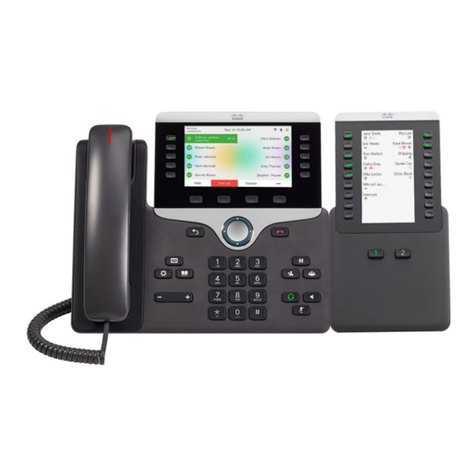
•Cisco IP Phone Key Expansion Module, on page 13
•Wall Mounts, on page 33
Accessories Overview for Cisco IP Phone 8800 Series with
Multiplatform Firmware
Table 1: Accessory Support for the Cisco IP Phone 8800 Series with Multiplatform Firmware
Cisco IP PhoneTypeAccessory
88658861885188458811 and 8841
Cisco Accessory
SupportedSupportedSupportedNot supportedNot supportedAdd-on
module
Cisco IP Phone 8800
Key Expansion
Module Supports up to 3 expansion
modules.
Supports up to 2
expansion
modules.
SupportedSupportedSupportedSupportedSupported
Wall Mount Kit
SupportedSupportedSupportedSupportedSupportedFootstand
SupportedSupportedSupportedSupportedSupportedCable Lock
SupportedSupportedSupportedNot supportedNot supportedUSBCisco Headset 520
Series
Cisco IP Phone Accessories
1
Cisco IP PhoneTypeAccessory
88658861885188458811 and 8841
SupportedSupportedSupportedSupportedSupportedStandard RJ9Cisco Headset 530
Series
SupportedSupportedSupportedNot supportedNot supportedUSB Adapter
Supported
SupportedSupportedSupportedSupportedStandard RJ9
and AUX
Cisco Headset 560
Series with Standard
Base
Cisco Headset 560
Series with Multibase
SupportedSupportedSupportedNot supportedNot supportedUSB
Not supported
Not supportedNot supportedNot supportedNot supportedBluetooth*Cisco Headset 730
SupportedSupportedSupportedNot supportedNot supportedUSB Adapter
SupportedSupportedSupportedNot supportedNot supportedUSB-C Cable
*—For the Bluetooth connection with Cisco IP Phone Multiplatform Phones, the limited call features (for example, answer or end
a call) are available. The call features will be fully supported in a future release. Currently, we recommend that you use the Cisco
Headset 730 by a USB adapter or a USB-C cable.
Third-Party Accessories
SupportedSupportedSupportedSupportedSupportedAnalog
Headsets: See Third
Party Headsets, on
page 8. This section
includes information
about each headset
type.
SupportedSupportedSupportedSupportedSupportedAnalog
Wideband
SupportedSupportedSupportedSupportedNot supportedBluetooth*
SupportedSupportedSupportedNot supportedNot supportedUSB
SupportedSupportedSupportedSupportedSupportedElectronic
Hookswitch
See Note 2.See Note 1.
SupportedSupportedNot supportedNot supportedNot supported
External PCMicrophones: See
External Speakers and
Microphone, on page
4.
SupportedSupportedNot supportedNot supportedNot supportedExternal PCSpeakers: See External
Speakers and
Microphone, on page
4.
Cisco IP Phone Accessories
2
Cisco IP Phone Accessories
1. If you connect your headset to the phone with the Y-cable (RJ-9 connector and AUX connector) , make
sure that you enable Electronic HookSwitch Control in the Audio Volume area from Voice >User tab
on the phone administration web page.
2. When you use the Electronic Hookswitch (EHS):
• The EHS connects to the Cisco IP Phone 8811, 8841, and 8845 with the auxiliary port.
• The EHS connects to the Cisco IP Phone 8851, 8861, and 8865 with the auxiliary port, the USB port,
or with Bluetooth.
Note
Connect the Footstand
If your phone is placed on a table or desk, connect the footstand to the back of the phone.
Procedure
Step 1 Insert the connectors into the slots.
Step 2 Press the footstand until the connectors snap into place.
Step 3 Adjust the angle of the phone.
Secure the Phone with a Cable Lock
You can secure your phone with a laptop cable lock up to 20 mm wide.
Procedure
Step 1 Take the looped end of the cable lock and wrap it around the object to which you want to secure your phone.
Step 2 Pass the lock through the looped end of the cable.
Step 3 Unlock the cable lock.
Step 4 Press and hold the locking button to align the locking teeth.
Step 5 Insert the cable lock into the lock slot of your phone and release the locking button.
Step 6 Lock the cable lock.
Cisco IP Phone Accessories
3
Cisco IP Phone Accessories
Connect the Footstand
External Speakers and Microphone
External speakers and microphones are plug-and-play accessories. You can connect an external PC-type
microphone and powered speakers (with amplifier) on the Cisco IP Phone by using the line in/out jacks.
Connecting an external microphone disables the internal microphone and connecting an external speaker
disables the internal phone speaker.
Using poor quality external audio devices, playing loudspeakers at very loud volumes, or placing the microphone
very close to the loudspeaker may result in undesirable echo for other parties on your speakerphone calls.
Note
Headsets
Important Headset Safety Information
High Sound Pressure—Avoid listening to high volume levels for long periods to prevent
possible hearing damage.
When you plug in your headset, lower the volume of the headset speaker before you put the headset on. If
you remember to lower the volume before you take the headset off, the volume will start lower when you
plug in your headset again.
Be aware of your surroundings. When you use your headset, it may block out important external sounds,
particularly in emergencies or in noisy environments. Don’t use the headset while driving. Don’t leave your
headset or headset cables in an area where people or pets can trip over them. Always supervise children who
are near your headset or headset cables.
Cisco Headsets 500 Series
You can use the Cisco Headset 500 Series with your Cisco IP Phone 8800 Series Multiplatform Phones. The
Cisco Headset 500 Series offers a more enhanced experience with:
• In-call indicators: LEDs on an ear plate
• Simplified call controls
• Customized audio
The supported headsets are:
• Cisco Headset 520 Series
• Cisco Headset 531 and 532
• Cisco Headset 560 Series (Standard Base and Multibase)
Cisco IP Phone Accessories
4
Cisco IP Phone Accessories
External Speakers and Microphone
Cisco Headset 521 and 522
The Cisco Headsets 521 and 522 are two wired headsets that have been developed for use on Cisco IP Phones
and devices. The Cisco Headset 521 features a single earpiece for extended wear and comfort. The Cisco
Headset 522 features two earpieces for use in a noisy workplace.
Both headsets feature a 3.5-mm connector for use on laptops and mobile devices. An inline controller with a
USB connector is also available for use on the Cisco IP Phone 8851, 8861, and 8865 with Multiplaform
Firmware. The controller is an easy way to answer your calls, and to access basic phone features such as hold
and resume, mute, and volume control.
The Cisco Headsets 521 and 522 require Multiplatform Firmware Release 11.2(3) or later version. Upgrade
your phones to the latest firmware before using these headsets.
To check your phone model and the firmware version, press Applications and select Status >Product
information. The Product name field shows your phone model. The Software version field shows the
installed load where you can get the firmware version.
Cisco Headset 521 and 522 Buttons and LED
Your controller buttons are used for basic call features.
Figure 1: Cisco Headset 521 and 522 Controller
The following table describes the Cisco Headset 521 and 522 controller buttons.
Table 2: Cisco Headset 521 and 522 Controller Buttons
DescriptionNameNumber
Toggle the microphone on and off.
Mute button
1
Adjust the volume on your headset.
Volume button (
and )
2
Cisco IP Phone Accessories
5
Cisco IP Phone Accessories
Cisco Headset 521 and 522
DescriptionNameNumber
Use to manage calls:
• Press once to answer an incoming call.
• Press and hold for 2 seconds to end a call.
• Press twice to reject an incoming call.
• Press once to put an active call on hold. Press again to
retrieve a call from hold.
Call button
3
Cisco Headset 561 and 562
The Cisco Headset 560 Series are two wireless headsets that are developed for Cisco products and services.
The Cisco Headset 561 features a single earpiece, and offers lightweight comfort. The Cisco Headset 562
features two earpieces for use in a noisy environment or busy office.
The Cisco Headset 560 Series use a headset base to connect with Cisco IP Phones and charge the headsets.
The available options for the base are Standard base and Multibase. The Cisco Headset 560 Series with
Standard Base support connection with a single source from a phone or a computer. The Cisco Headset 560
Series with Multibase support multiple sources from phones, computers, and Bluetooth-paired devices and
provide an easy and intuitive switch among the connected sources.
You can connect the Cisco Headset 560 Series with any of the following:
• RJ9 and AUX connector (Y-cable)—Supported on Cisco IP Phones 8811, 8841, 8845, 8851, 8861, and
8865 with multiple platforms.
• USB connector—Supported on Cisco IP Phones 8851, 8861, and 8865 with multiple platforms.
The Cisco Headset 560 Series require Multiplatform Firmware Release 11.2(3) and higher. Upgrade your
phones to the latest firmware before using these headsets.
To check your phone model and the firmware version, press Applications and select Status >Product
information. The Product name field shows your phone model. The Software version field shows the
installed load where you can get the firmware version.
Cisco Headset 561 and 562 Buttons and LED
Your headset buttons are used for basic call features.
Cisco IP Phone Accessories
6
Cisco IP Phone Accessories
Cisco Headset 561 and 562
Figure 2: Cisco Headset 561 and 562 Headset Buttons
The following table describes the Cisco Headset 561 and 562 Headset buttons.
Table 3: Cisco Headset 561 and 562 Headset Buttons
DescriptionNameNumber
Use to power the headset on and off.
Press and hold for 4 seconds to power on/off the headset.
Incoming and active call management depends upon if you have one call
or multiple calls.
One call:
• Press once to answer incoming calls.
• Press once to put an active call on hold. Press again to retrieve the call
from hold.
• Press twice to reject an incoming call.
Multiple calls:
• Press once to put an active call on hold, and to answer a second
incoming call.
• Press once to put a current call on hold and press again to resume a
call.
• Press and hold for 2 seconds to end the current call and press again to
resume a held call.
• Press and hold for 2 seconds to end an active call, and to answer
another incoming call.
• Press twice to stay on a current call, and to reject a second incoming
call.
Power and Call button
1
Cisco IP Phone Accessories
7
Cisco IP Phone Accessories
DescriptionNameNumber
Toggle the microphone on and off. When Mute on the headset is enabled:
• The Mute button on the phone lights up.
• The Mute button on the headset base lights up. (For Multibase
only)
Mute button
2
Adjust the volume on your headset.
Volume button ( and )
3
Shows the headset status:
• Blinking red—Incoming call.
• Steady red—Active call.
• Flashing white every 6 seconds—The headset is paired and idle.
• Blinking white—Firmware upgrade is in process or the headset is
pairing with the base station.
LED4
Charge Cisco Headset 561 and 562
Use the headset base to charge the headset.
Procedure
Place the headset into the socket on the base.
The LEDs on the base station indicate the charging status. When the headset is fully charged, the five LEDs
on the base are steady white. If the LEDs don't light up, remove the headset from the base and try again.
Third Party Headsets
Cisco Systems performs internal testing of third-party headsets for use with Cisco IP Phones. But Cisco does
not certify or support products from headset or handset vendors.
Headsets connect to your phone using either the USB or the auxiliary port. Depending upon your headset
model, you have to adjust your phone's audio settings for the best audio experience, including the headset
sidetone setting.
If you have a third-party headset, and you apply a new sidetone setting, then wait one minute and reboot the
phone so the setting is stored in flash.
The phone reduces some background noise that a headset microphone detects. You can use a noise canceling
headset to further reduce the background noise and improve the overall audio quality.
If you are considering a third-party headset, we recommend the use of good quality external devices; for
example, headsets that are screened against unwanted radio frequency (RF) and audio frequency (AF) signals.
Cisco IP Phone Accessories
8
Cisco IP Phone Accessories
Charge Cisco Headset 561 and 562
Depending on the quality of headsets and their proximity to other devices, such as mobile phones and two-way
radios, some audio noise or echo may still occur. Either the remote party or both the remote party and the
Cisco IP Phone user may hear an audible hum or buzz. A range of outside sources can cause humming or
buzzing sounds; for example, electric lights, electric motors, or large PC monitors.
Sometimes, use of a local power cube or power injector may reduce or eliminate hum.
Note
Environmental and hardware inconsistencies in the locations where Cisco IP Phones are deployed mean that
no single headset solution is optimal for all environments.
We recommend that customers test headsets in the intended environment to determine performance before
making a purchasing decision to deploy on a large scale.
You can use only one headset at a time. The most-recently connected headset is the active headset.
Headset Configuration on Your Phone
Cisco Headset 500 Series Customization
The user can customize the headset's gain or microphone volume, sidetone or feedback settings, and test the
microphone. Make sure that the headset is connected to the phone using one of the following connections:
• Cisco Headset 520 Series with the inline USB controller via the USB connector
• Cisco Headset 531 and 532 with the USB adapter via the USB connector
• Cisco Headset 560 Series Standard Base or Multibase with the Y-cable via the AUX and the RJ-9
connectors, or with the USB cable via the USB connector
For information on headset setup, see Cisco IP Phone 8800 Series Multiplatform Phones User Guide.
Set the Upgrade Rule for the Cisco Headset
You can upgrade the firmware of a Cisco headset by connecting it to a Cisco IP Phone Multiplatform Phone.
Before the user performs the upgrade, you must set the upgrade rule on the phone administration web page.
When the headset is connected to the phone, the phone automatically detects the new version of the headset
firmware, then prompts the user to perform the upgrade.
The supported connections for the upgrade are:
• Cisco Headset 520 Series: USB cable
• Cisco Headset 560 Series: USB cable and Y-Cable (RJ-9 and AUX connector)
• Cisco Headset 700 Series: USB cable
The headset settings are not erased by a phone reset. The upgrade rule supports HTTP, HTTPS, and TFTP
protocols.
The release of the Cisco Headset provides the headset XML file that can be used for the firmware upgrade.
If the software version in the file is later than the firmware on the headset, the user is prompted to upgrade
the headset on the phone screen. The user can choose to upgrade the headset immediately or postpone it to a
later time.
Cisco IP Phone Accessories
9
Cisco IP Phone Accessories
Headset Configuration on Your Phone
Before you begin
Access the phone administration web page. See Access the Phone Web Interface.
Procedure
Step 1 Select Voice >Provisioning.
Step 2 Under the Cisco Headset Firmware Upgrade section, find the parameter Cisco Headset Upgrade Rule.
Step 3 Specify the TFTP, HTTP, or HTTPS protocol, an IP address of the headset upgrade device, and the name of
the headset XML file. Enter the values as a single string in the parameter.
Do not change the headset XML file contents.
Caution
For example, tftp://10.74.51.81/prov/headset/1-6-0-162/ciscoheadsetfirmware.xml
You can also configure this parameter in the configuration file (cfg.xml):
<Cisco_Headset_Upgrade_Rule
ua="na">tftp://10.74.51.81/prov/headset/1-6-0-162/ciscoheadsetfirmware.xml</Cisco_Headset_Upgrade_Rule>
Step 4 Click Submit All Changes.
If a new version of the headset firmware is detected, the phone displays an upgrade prompt.
Audio Quality
Beyond physical, mechanical, and technical performance, the audio portion of a headset must sound good to
the user and to the party on the far end. Sound quality is subjective, and we cannot guarantee the performance
of any third-party headset. However, various headsets from leading headset manufacturers are reported to
perform well with Cisco IP Phones.
Cisco doesn't recommend or test any third-party headsets with their products. For information about third-party
headset support for Cisco products, go to the manufacturer's web site.
Cisco does test the Cisco headsets with the Cisco IP Phones. For information about Cisco Headsets and Cisco
IP Phone support, see https://www.cisco.com/c/en/us/products/collaboration-endpoints/headsets/index.html.
Analog Headsets
The phone cannot detect when an analog headset is plugged in. For this reason, the analog headset displays
by default in the Accessories window on the phone screen.
Displaying the analog headset as the default allows users to enable wideband for the analog headset.
USB Headsets
Wired and wireless USB headsets are supported. You can connect one USB headset (or the base station for
a wireless headset) to either the back USB port (if your phone has this port) or to the side USB port.
Cisco IP Phone Accessories
10
Cisco IP Phone Accessories
Audio Quality
Select a USB Headset
You can only plug in one USB headset. If you are using an analog headset, you can switch to your USB
headset by using the Accessories window of the phone.
Procedure
Step 1 On your phone, press Applications .
Step 2 Select Status.
Step 3 Select Accessories.
Step 4 Press the Navigation cluster, up or down, to select the USB headset.
Stop Using a USB Headset
You can stop using your USB headset and select a different headset in the Accessories window of the phone.
Procedure
Step 1 On your phone, press Applications .
Step 2 Select Status.
Step 3 Select Accessories.
Step 4 Press the Navigation cluster, up or down, to select a different headset.
Wireless Headsets
You can use most wireless headsets with your phone. For a list of supported wireless headsets, see
http://www.cisco.com/c/en/us/products/unified-communications/uc_endpoints_accessories.html
Refer to your wireless headset documentation for information about connecting the headset and using the
features.
Bluetooth Wireless Headsets
For a list of supported headsets, see http://www.cisco.com/c/en/us/products/unified-communications/uc_
endpoints_accessories.html.
Bluetooth enables low-bandwidth wireless connections within a range of 30 feet (10 meters). The best
performance is in the 3- to 6-foot (1- to 2-meter) range. Bluetooth wireless technology operates in the 2.4
GHz band, which is the same as the 802.11b/g band.
Cisco IP Phones use a shared key authentication and encryption method to connect up to fifty headsets, one
at a time. The last connected headset is used as the default. Pairing is typically performed once for each
headset.
Cisco IP Phone Accessories
11
Cisco IP Phone Accessories
Select a USB Headset
After a device is paired, the Bluetooth connection is maintained as long as both devices (phone and headset)
are enabled and within range of each other. The connection typically reestablishes itself automatically if either
of the devices powers down then powers up. However, some headsets require user action to reestablish the
connection.
The Bluetooth icon indicates that Bluetooth is on, regardless of whether a device is connected or not.
Potential interference issues can occur. We recommend that you reduce the proximity of other 802.11b/g
devices, Bluetooth devices, microwave ovens, and large metal objects. If possible, configure other 802.11
devices to use the 802.11a channels. Use 802.11a, 802.11n or 802.11ac that operates in the 5 GHz band.
For a Bluetooth wireless headset to work, it does not need to be within direct line-of-sight of the phone.
However, some barriers, such as walls or doors, and interference from other electronic devices, can affect the
connection.
When headsets are more than 30 feet (10 meters) away from the Cisco IP Phone, Bluetooth drops the connection
after a 15- to 20-second timeout. If the paired headset comes back into range of the Cisco IP Phone and the
phone is not connected to another Bluetooth headset, the in-range Bluetooth headset automatically reconnects.
For certain phone types that operate in power-save modes, the user can wake up the headset by tapping on
the operational button to initiate the reconnect.
You must enable the headset and then add it as a phone accessory.
The phone supports various Handsfree Profile features that enable you to use hands-free devices (such as
Bluetooth wireless headsets) to perform certain tasks without handling the phone. For example, instead of
pressing Redial on the phone, users can redial a number from their Bluetooth wireless headset by following
instructions from the headset manufacturer.
These hands-free features apply to Bluetooth wireless headsets that are used with the Cisco IP Phone8851
and 8861:
• Answer a call
• End a call
• Change the headset volume for a call
• Redial
• Caller ID
• Divert
• Hold and accept
• Release and accept
Hands-free devices may differ as to feature activation. Device manufacturers may also use different terms
when referring to a feature.
Cisco IP Phone Accessories
12
Cisco IP Phone Accessories
Only one headset type works at any given time. If you use both a Bluetooth headset and an analog headset
that are attached to the phone, enabling the Bluetooth headset disables the analog headset. To enable the analog
headset, disable the Bluetooth headset. Plugging a USB headset into a phone that has Bluetooth headset
enabled disables both the Bluetooth and analog headset. If you unplug the USB headset, you can either enable
or disable the Bluetooth headset to use the analog headset.
Users can set their Bluetooth headset as the preferred headset, even when a USB headset is connected to the
phone. On the phone, the user selects Applications >Userpreferences>Audio preferences>Preferred
audio device and chooses Bluetooth as the preferred audio device.
Important
For information about how to use your Bluetooth wireless headset, see:
•Cisco IP Phone 8811, 8841, 8851, and 8861 User Guide for Cisco Unified Communications Manager
• User guides provided with your headset
Cisco IP Phone Key Expansion Module
Cisco IP Phone Key Expansion Module Setup Overview
Figure 3: Key Expansion Module with Single LCD Screen
Figure 5: Cisco IP Phone 8865 Key Expansion Module with Dual
Screen
Figure 4: Cisco IP Phone 8851/8861 Key Expansion Module with
Dual Screen
Cisco IP Phone Accessories
13
Cisco IP Phone Accessories
Cisco IP Phone Key Expansion Module
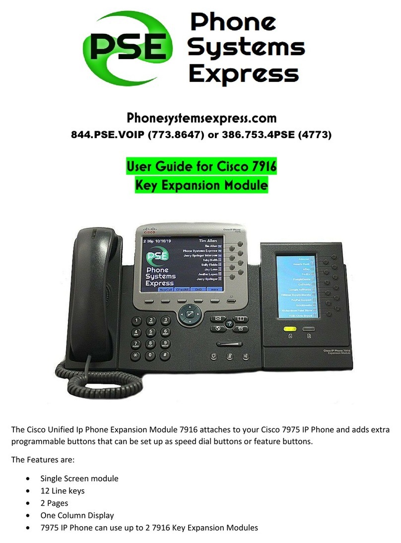
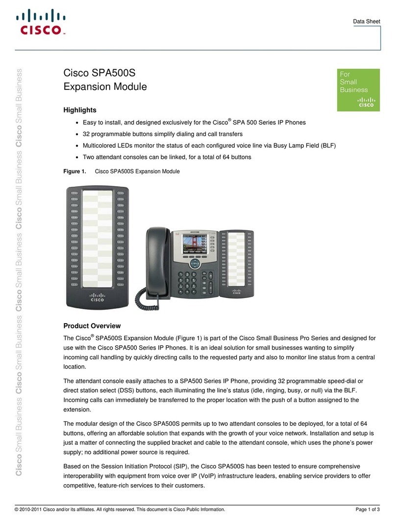
The Cisco IP Phone 8800 Key Expansion Module adds extra programmable buttons to the phone. The
programmable buttons can be set up as phone speed-dial buttons, or phone feature buttons.
There are 3 expansion modules available:
• Cisco IP Phone 8800 Key Expansion Module—Single LCD screen module, 18 line keys, 2 pages,
two-column display only.
• Cisco IP Phone 8851/8861 Key Expansion Module—Dual LCD screen module for audio phones, 14 line
keys, 2 pages, one-column display only.
• Cisco IP Phone 8865 Key Expansion Module—Dual LCD screen module for video phones, 14 line keys,
2 pages, one-column display only.
The Cisco IP Phone 8851/8861 Key Expansion Module and the Cisco IP Phone 8865 Key Expansion Module
require Firmware Release 11.2(3) or later.
Note
You can use more than one expansion module per phone. But each module must be the same type. You cannot
mix Cisco IP Phone 8800 Key Expansion Module with a Cisco IP Phone 8851/8861 Key Expansion Module
or with a Cisco IP Phone 8865 Key Expansion Module. You cannot mix audio expansion modules with video
expansion modules. You also cannot use a video expansion module on an audio phone or an audio expansion
module on a video phone.
The following table lists the phones and the number of key expansion modules that each model supports.
Table 4: Cisco IP Phones and Supported Cisco IP Phone 8800 Key Expansion Module
Supported Number of Key Expansion Modules and ButtonsCisco IP Phone Model
2; single LCD screen, 18 line keys, two pages, providing 72
buttons
Cisco IP Phone 8851
3; single LCD screen, 18 line keys, two pages, providing 108
buttons
Cisco IP Phone 8861
3; single LCD screen, 18 line keys, two pages, providing 108
buttons,
Cisco IP Phone 8865
Table 5: Cisco IP Phones and Supported Cisco IP Phone 8851/8861 Key Expansion Module and Cisco IP Phone 8865 Key Expansion Module
Supported Numbers of Key Expansion Modules and ButtonsCisco IP Phone Model
2; dual LCD screen, 14 line keys, two pages, providing 56 buttonsCisco IP Phone 8851
3; dual LCD screen, 14 line keys, two pages, providing 84 buttonsCisco IP Phone 8861
3; dual LCD screen, 14 line keys, two pages, providing 84 buttonsCisco IP Phone 8865
Cisco IP Phone Accessories
14
Cisco IP Phone Accessories
Key Expansion Module Power Information
If you use a key expansion module with your IP phone, then Power over Ethernet (PoE) is enough to power
your expansion modules. But, your phone must have an IP address in order to charge the expansion module.
A power cube is needed for smartphone or tablet charging when your key expansion module is attached.
A key expansion module uses 48V DC, 5W per module. If you are charging a smartphone or a tablet, note
the following:
• Side USB: Up to 500mA/2.5W charging
• Back USB: Fast charging, Supports up to 2.1A/10.5W charging
Table 6: Power-Supply Compatibility for Cisco IP Phone 8800 Key Expansion Module
Cisco IP Phone Power Cube 4802.3at PoE802.3af Power over Ethernet
(PoE)
Configuration
YesYesYes8851 with 1 key expansion
module
YesNo
See the third note below
No8851with 2 key expansion
modules
YesYesNo8861 with 1 key expansion
module
YesYes
See the first note below
No8861 with 2 key expansion
modules
YesYes
See the first note below
No8861 with 3 key expansion
modules
• The fast-charging feature on the back USB does not work when more than one key expansion module
is attached to a Cisco IP Phone 8861 using 802.3at PoE.
• The fast-charging feature on the back USB doesn’t work when more than one key expansion module is
attached to a Cisco IP Phone 8861, unless Cisco Universal PoE (UPoE) is used.
•Cisco IP Phone 8851 with 2 key expansion modules works on 802.3at PoE only with v08 or later hardware.
You can find the phone version information on the lower back of the phone as part of the TAN and PID
label. Version information is also located on the individual phone packaging.
Note
Cisco IP Phone Accessories
15
Cisco IP Phone Accessories
Key Expansion Module Power Information
Table 7: Power-Supply Compatibility for Cisco IP Phone 8851/8861 Key Expansion Module and Cisco IP Phone 8865 Key Expansion Module
Cisco IP Phone Power Cube 4802.3at PoE802.3af Power over Ethernet
(PoE)
Configuration
YesYesYes8851 with 1 key expansion
module
YesYes
See the third note below
No8851with 2 key expansion
modules
YesYesNo8861 and 8865 with 1 key
expansion module
YesYes
See the first note below
No8861 and 8865 with 2 key
expansion modules
YesYes
See the first note below
No8861 and 8865 with 3 key
expansion modules
• The fast-charging feature on the back USB does not work when more than one key expansion module
is attached to a Cisco IP Phone 8861 and 8865 using 802.3at PoE.
• The fast-charging feature on the back USB doesn’t work when more than one key expansion module is
attached to a Cisco IP Phone 8861 and 8865, unless Cisco Universal PoE (UPoE) is used.
•Cisco IP Phone 8851 with 2 key expansion modules works on 802.3at PoE only with v08 or later hardware.
You can find the phone version information on the lower back of the phone as part of the TAN and PID
label. Version information is also located on the individual phone packaging.
Note
Connect a Key Expansion Module to a Cisco IP Phone
If you want to install more than one key expansion module, you repeat steps 7-9 to connect the other key
expansion modules together.
Procedure
Step 1 Unplug the Ethernet cable from the phone.
Step 2 If installed, remove the footstand from the phone.
Step 3 Locate the accessory connector covers on the side of the phone.
This diagram shows the location.
Cisco IP Phone Accessories
16
Cisco IP Phone Accessories
Connect a Key Expansion Module to a Cisco IP Phone
Step 4 Remove the two accessory connector covers, as shown in the diagram.
The slots are designed for the spine connector only. Insertion of other objects will cause permanent
damage to the phone.
Caution
Step 5 Position the phone so that the front of the phone faces up.
Step 6 Connect one end of the key expansion module spine connector to the accessory connector on the Cisco IP
Phone.
a) Align the spine connector with the accessory connector ports.
Install the connector in the orientation shown in the following diagrams.
Note
b) Firmly press the spine connector into the phone.
Cisco IP Phone Accessories
17
Cisco IP Phone Accessories
This diagram shows the spine connector.
This diagram shows the installation of the spine connector.
Step 7 Connect the other end of the spine connector to the key expansion module as shown in this diagram.
a) Align the spine connector with the key expansion module accessory connector ports.
b) Firmly press the key expansion module into the spine connector.
Cisco IP Phone Accessories
18
Cisco IP Phone Accessories
Step 8 (Optional) Use a second key expansion module spine connector to connect the second key expansion module
to the first key expansion module.
Step 9 (Optional) Use a third key expansion module spine connector to connect the third key expansion module to
the second key expansion module.
Step 10 Use a screwdriver to fasten the screws into the phone.
This step ensures that the phone and key expansion module remain connected at all times. This diagram shows
the location of the screw holes on the phone and one key expansion module.
Cisco IP Phone Accessories
19
Cisco IP Phone Accessories
Make sure that the screws are fully inserted into the phone and tightened.
If you lose any screws, the phone uses a standard M3 0.5x5.0mm screw.
Note
Step 11 (Optional) Install the footstands on the phone and on the key expansion module, and adjust both footstands
to rest evenly on the work surface.
Step 12 Plug the Ethernet cable into the phone.
Connect Two or Three Key Expansion Modules to a Cisco IP Phone
Procedure
Step 1 Unplug the Ethernet cable from the phone.
Step 2 If installed, remove the footstand from the phone.
Step 3 Locate the accessory connector covers on the side of the phone.
This diagram shows the location.
Cisco IP Phone Accessories
20
Cisco IP Phone Accessories
Connect Two or Three Key Expansion Modules to a Cisco IP Phone

Other manuals for 8800 Series

47

This manual suits for next models

6

Other Cisco Telephone Accessories manuals

Cisco SPA500S User manual

Cisco

Cisco SPA500S User manual

Cisco BEKEM User manual

Cisco

Cisco BEKEM User manual

Cisco CP-7914 - 7914 - Key Expansion Module User manual

Cisco

Cisco CP-7914 - 7914 - Key Expansion Module User manual

Cisco SPA500S User manual

Cisco

Cisco SPA500S User manual

Cisco Small Business Pro SPA 504G User manual

Cisco

Cisco Small Business Pro SPA 504G User manual

Cisco Small Business SPA2102 User manual

Cisco

Cisco Small Business SPA2102 User manual

Cisco SPA500DS User manual

Cisco

Cisco SPA500DS User manual

Cisco Small Business Pro SPA9000 Instruction Manual

Cisco

Cisco Small Business Pro SPA9000 Instruction Manual

Cisco 7916 User manual

Cisco

Cisco 7916 User manual

Cisco WBP54G - Small Business Pro Wireless-G... User manual

Cisco

Cisco WBP54G - Small Business Pro Wireless-G... User manual

Cisco WBP54G - Small Business Pro Wireless-G... User manual

Cisco

Cisco WBP54G - Small Business Pro Wireless-G... User manual

Cisco PAP2T User manual

Cisco

Cisco PAP2T User manual

Cisco ATA 187 User manual

Cisco

Cisco ATA 187 User manual

Cisco Unified IP Phone Expansion Module 7915 User manual

Cisco

Cisco Unified IP Phone Expansion Module 7915 User manual

Cisco 7916 User manual

Cisco

Cisco 7916 User manual

Cisco UC 520 User manual

Cisco

Cisco UC 520 User manual

Popular Telephone Accessories manuals by other brands

iCreation i-450 Product information guide

iCreation

iCreation i-450 Product information guide

BesTrix SMARTCLAMP 10 AV user manual

BesTrix

BesTrix SMARTCLAMP 10 AV user manual

Monacor SONIDO manual

Monacor

Monacor SONIDO manual

Bpt IT/300 INSTALLATION DIAGRAMS

Bpt

Bpt IT/300 INSTALLATION DIAGRAMS

Grandstream Networks HandyTone-486 user manual

Grandstream Networks

Grandstream Networks HandyTone-486 user manual

Avaya INDeX 9.1 20DT user guide

Avaya

Avaya INDeX 9.1 20DT user guide

NEC SL1000 Programming manual

NEC

NEC SL1000 Programming manual

NetComm V100 user guide

NetComm

NetComm V100 user guide

SoftBank 823P user guide

SoftBank

SoftBank 823P user guide

Sena 20S user guide

Sena

Sena 20S user guide

Plantronics DA50 quick start guide

Plantronics

Plantronics DA50 quick start guide

SSS Siedle ZTCV 850-0 Product information

SSS Siedle

SSS Siedle ZTCV 850-0 Product information

Texecom Speech Dailler Operator's manual

Texecom

Texecom Speech Dailler Operator's manual

Jabra GN 8120 USB Quick setup guide

Jabra

Jabra GN 8120 USB Quick setup guide

Iluv i601 instruction manual

Iluv

Iluv i601 instruction manual

Viking K-1900-5 Technical practice

Viking

Viking K-1900-5 Technical practice

Hunter Cypress Grove 19249 installation instructions

Hunter

Hunter Cypress Grove 19249 installation instructions

Polycom KIRK 5020 quick guide

Polycom

Polycom KIRK 5020 quick guide

manuals.online logo
manuals.online logoBrands
  • About & Mission
  • Contact us
  • Privacy Policy
  • Terms and Conditions

Copyright 2025 Manuals.Online. All Rights Reserved.