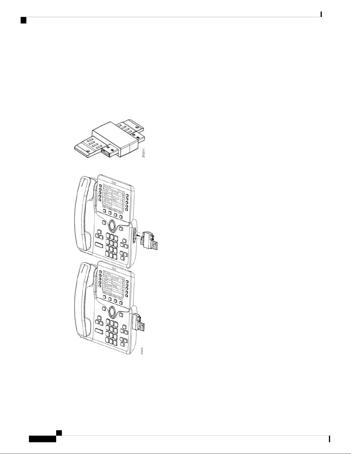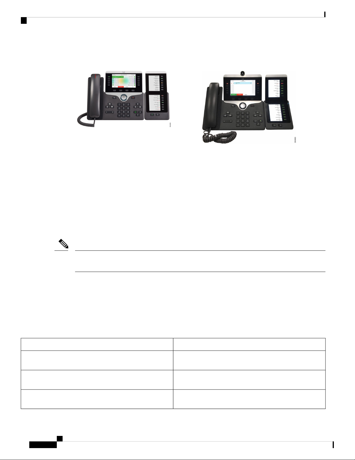
Figure 3: Cisco IP Phone 8865 Key Expansion Module with Dual
Screen
Figure 2: Cisco IP Phone 8851/8861 Key Expansion Module with
Dual Screen
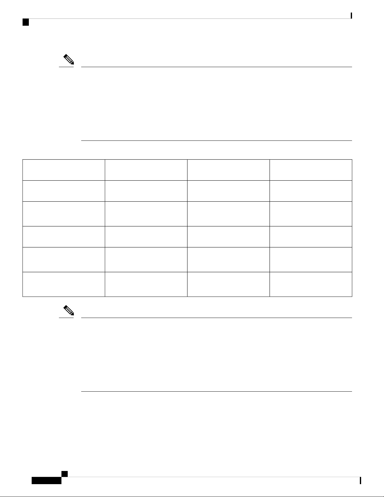
The Cisco IP Phone 8800 Key Expansion Module adds extra programmable buttons to the phone. The
programmable buttons can be set up as phone speed-dial buttons, or phone feature buttons.
There are 3 expansion modules available:
• Cisco IP Phone 8800 Key Expansion Module—Single LCD screen module, 18 line keys, 2 pages,
two-column display only.
• Cisco IP Phone 8851/8861 Key Expansion Module—Dual LCD screen module for audio phones, 14 line
keys, 2 pages, one-column display only.
• Cisco IP Phone 8865 Key Expansion Module—Dual LCD screen module for video phones, 14 line keys,
2 pages, one-column display only.
The Cisco IP Phone 8851/8861 Key Expansion Module and the Cisco IP Phone 8865 Key Expansion Module
require Firmware Release 11.2(3) or later.
Note
You can use more than one expansion module per phone. But each module must be the same type. You cannot
mix Cisco IP Phone 8800 Key Expansion Module with a Cisco IP Phone 8851/8861 Key Expansion Module
or with a Cisco IP Phone 8865 Key Expansion Module. You cannot mix audio expansion modules with video
expansion modules. You also cannot use a video expansion module on an audio phone or an audio expansion
module on a video phone.
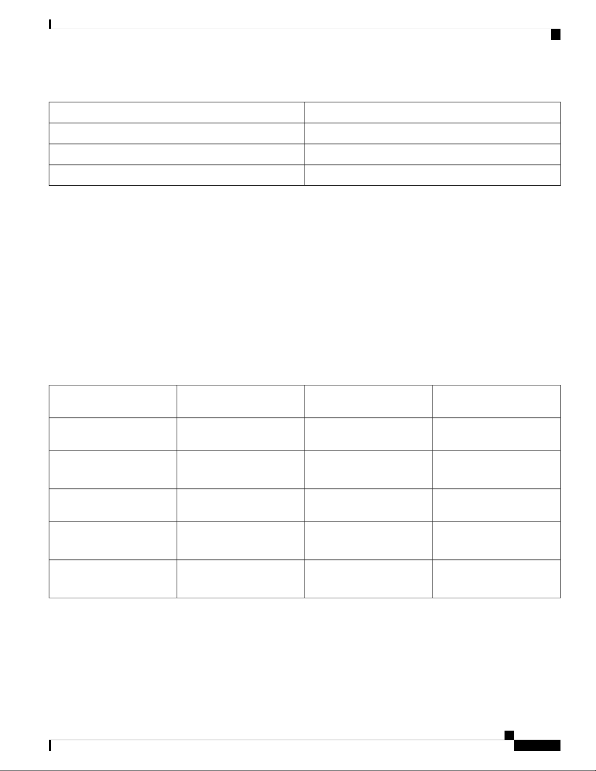
The following table lists the phones and the number of key expansion modules that each model supports.
Table 1: Cisco IP Phones and Supported Cisco IP Phone 8800 Key Expansion Module
Supported Number of Key Expansion Modules and ButtonsCisco IP Phone Model
2; single LCD screen, 18 line keys, two pages, providing 72
buttons
Cisco IP Phone 8851
3; single LCD screen, 18 line keys, two pages, providing 108
buttons
Cisco IP Phone 8861
3; single LCD screen, 18 line keys, two pages, providing 108
buttons,
Cisco IP Phone 8865
Cisco IP Phone Key Expansion Module
2
Cisco IP Phone Key Expansion Module
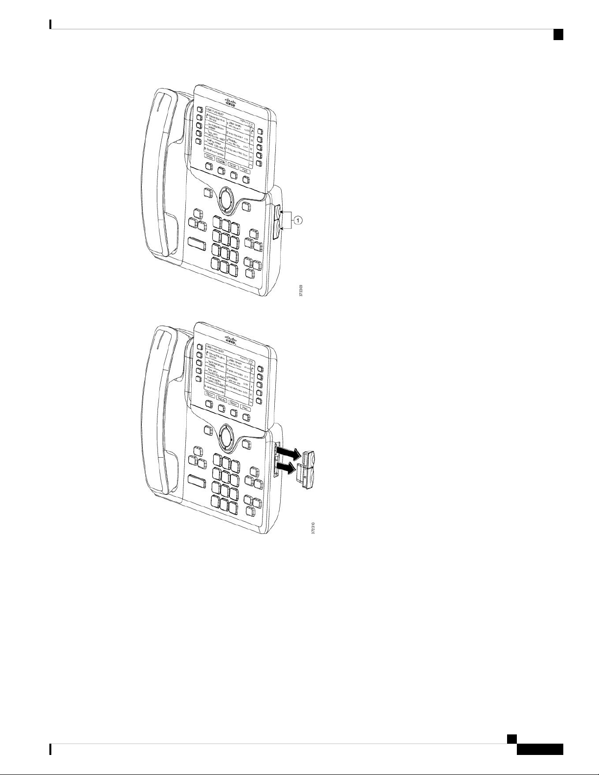
Cisco IP Phone Key Expansion Module Setup Overview