manuals.online logo
Brands
  1. Home
  2. •
  3. Brands
  4. •
  5. Cisco
  6. •
  7. Telephone Accessories
  8. •
  9. Cisco 7916 User manual

Cisco 7916 User manual

844.PSE.VOIP (773.8647) or 386.753.4PSE (4773)
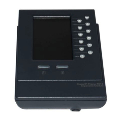
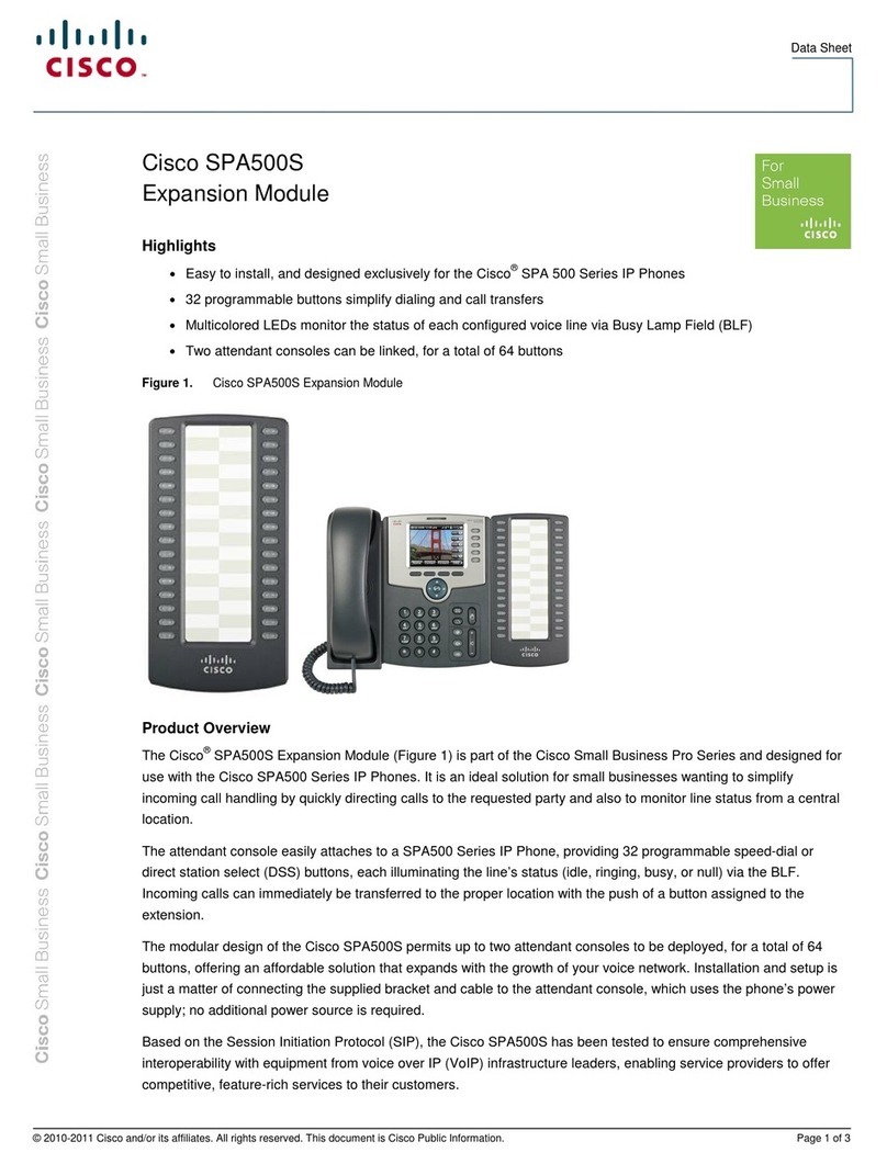
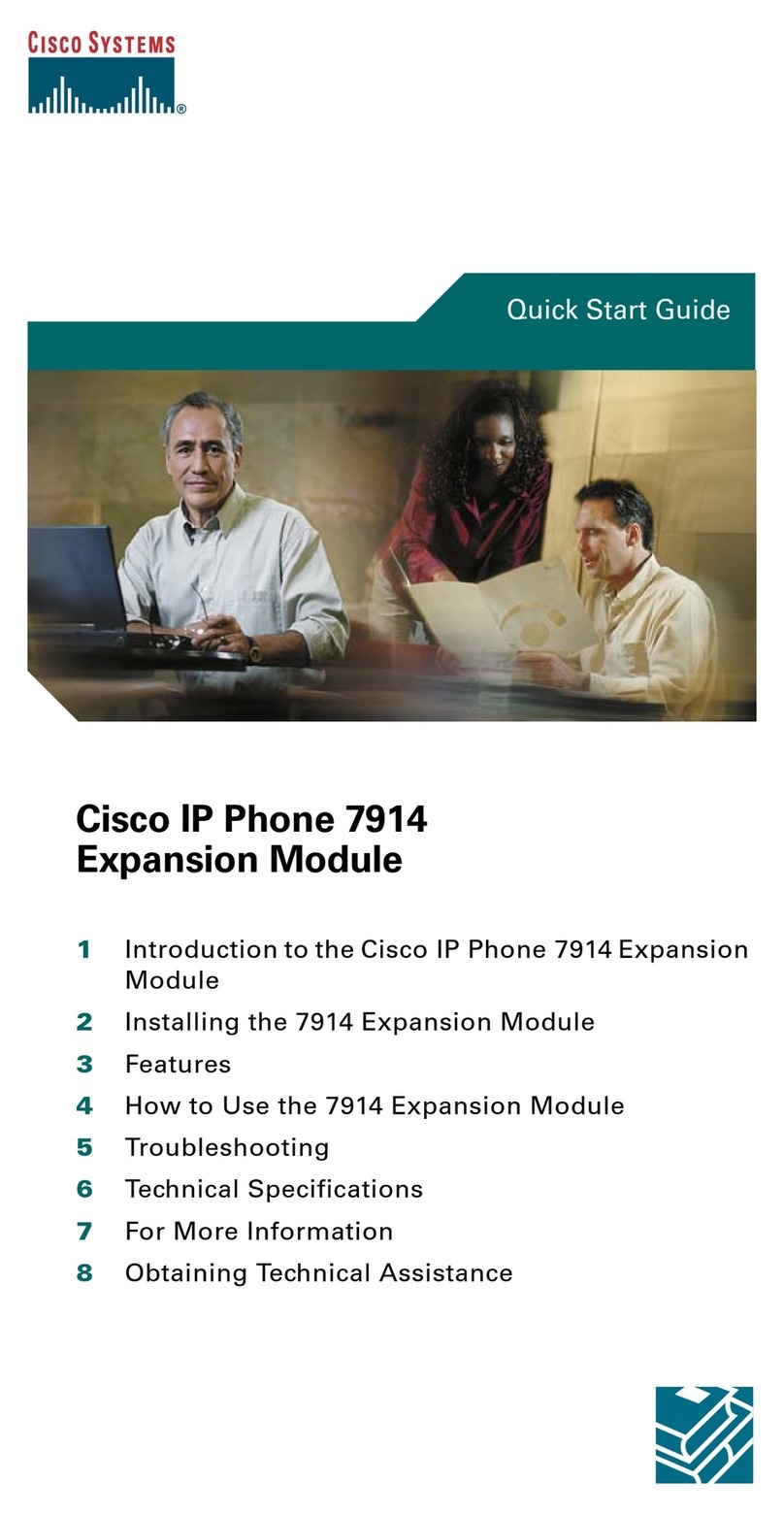
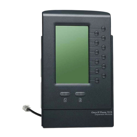
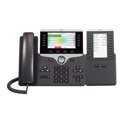
The Cisco Unified Ip Phone Expansion Module 7916 attaches to your Cisco 7975 IP Phone and adds extra
programmable buttons that can be set up as speed dial buttons or feature buttons.
The Features are:
•Single Screen module
•12 Line keys
•2 Pages
•One Column Display
•7975 IP Phone can use up to 2 7916 Key Expansion Modules
•If you are using Power Over Ethernet (PoE) to power your 7975 IP Phone, you will need a power
supply unit for your 7916 Key Expansion Module.
•If you are using a power supply to power your 7975 and only using one 7916 Key Expansion
Module, you do NOT need a power supply. If you are using two Key Expansion Modules, you will
need an additional power supply.
Removing the Footstand
Step 1 Unplug the network and power connections.
Step 2 Unplug the handset, and unplug the headset if one is attached to the phone.
Step 3 Turn the phone over and lay it on a protected flat surface to prevent it from being scratched.
Step 4 Locate the two foot pins on the footstand.
Step 5 Use a flathead screw driver to carefully push on one of the foot pins to release it. Then carefully
push on the other foot pin to release it.
Step 6 Lift off the footstand and store it separately.
Step 1 Position the support bar on the back of the 7975 IP Phone so that it fits flush with the phone.
Step 2 Locate the two connector pins.
Step 3 Use a flathead screwdriver to carefully push each of the connector pins so that the support bar
is firmly fastened to the Cisco 7975 IP Phone.
Step 1 Position the phone so that the front of the phone is facing up.
Step 2 Line up the two open slots on the bottom of the Cisco 7916 expansion module with the two
hooks on the support bar.
Step 3 Insert the hooks into the slots and then rotate the top of the Cisco 7916 expansion module into
the support bar so that it rests flush with the bar.
Step 4 Tighten the thumbscrew on the back of the expansion module.
Note If you are connecting two expansion modules, repeat steps 2, 3, and 4 for the second expansion
module.
Refer to the following table, which depicts the “in” and “out” icons on the AUX jacks.
Step 1 Plug one end of the interface cable into the jack labeled AUX on the Cisco 7975 IP Phone.
Step 2 Plug the other end of the interface cable into the AUX jack with the “in” icon underneath it on
the 7916 expansion module.
Note If you are installing a second expansion module 7916, continue with steps 3 and 4. Otherwise
go to the “Connect the Power Supply Unit” section of this guide.
Step 3 Plug one end of the second interface cable into the AUX jack with the “out” icon underneath it
on the first expansion module (the one closest to the phone).
Step 4 Plug the other end of the second interface cable into the AUX jack with the “in” icon
underneath it on the second expansion module.
Step 1 Depending on how your 7975 IP Phone is powered with one or two Expansion Modules,
perform one of the following actions to connect the power supply:
•Your phone is powered over the Ethernet with one Expansion Module:
Connect the power supply unit to the AC adapter port on the Expansion Module and plug the
other end into a standard power outlet in the wall.
•If your phone is powered over the Ethernet with two Expansion Modules:
Connect the power supply unit to the AC adapter port on the Expansion Module closest to the
7975 phone and plug the other end into a standard electrical power outlet in the wall.
•If your phone is powered with a power supply unit and only using one Expansion Module:
Reconnect the original 7975 phone power supply unit to the AC adapter port on the 7975 phone
and plug the other end into a standard electrical power outlet in the wall.
•If your phone is powered with a power supply unit and using two Expansion Modules:
Connect a second power supply unit to the AC adapter port on the Expansion Module closest to
the 7975 phone and plug the other end into a standard electrical power outlet in the wall.
Step 2 Reconnect the 7975 phone handset and network connection.
Step 1 Locate the three hooks on the footstand.
Step 2 Position the hooks so that they align with the open slots on the support bar.
Note There are four positions on each of the three sets of open slots on the support bar. This lets you
choose the angle of the footstand.
Step 3 Insert the footstand hooks into the support bar and push in slightly to make the connection.
At this point your phone should be starting up. Please continue reading to see
the features of the 7916 key expansion module, how to use them, and
troubleshooting below.
After the 7916 Expansion module is installed, upon startup the buttons all show a steady amber light.
The Cisco logo, load name, segment name, and download percentage are displayed. After the firmware
is installed, the LCD screen refreshes, and the buttons all go off and any line appearances are displayed
in the LCD screen. You can then start using the Expansion Module.
1) Phone screen –Displays the phone number, speed dial number (or name/other text label),
phone service, phone feature or Privacy assigned to each button. Icons indicating line status
appear similar to and function the same as those on your 7975 phone that it is attached to.
2) Lighted Buttons –12 buttons. Each corresponds to one line (just like the 7975 phone). The lights
beneath each button indicate the state of the corresponding line as follows:
•Light Off: Line available
•Steady Green Light: Line in use by you
•Steady Red Light: Line in use by someone else
•Flashing Amber Light: Line ringing
•Flashing Green Light: You have a call on hold
•Flashing Green Light: Someone else has a call on hold
•Steady Green Light: Call transfer
3) Shift Buttons –2 buttons. Each button corresponds to one page of the 12 Line keys. Page one is
labeled with the number 1 and page two is labeled with the page number 2. The lights beneath
each button indicate the state of the page as follows:
•Steady Green Light: Page is active
•Light Off: Page is inactive
•Flashing Amber Light: A call is ringing on an inactive page
Note If Privacy is programmed for one of your buttons, you can keep your call information private from
users who share your lines. Simply press the Privacy button when receiving an incoming call. With
Privacy enabled, other shared lines are blocked from joining your calls.
No Display on the 7916 Expansion Module
•Verify that all of the cable connections are
correct
•Verify that you have power to the 7916
Expansion Module
Buttons on the first 7916 Expansion Module are
all Amber
•Verify that the interface cable between the
7975 Phone and the 7916 Expansion
Module is connected.
•Verify with your system administrator that
your 7916 Expansion Module is defined in
Cisco Unified Communications Manager.
Buttons on the second 7916 Expansion Module
are all Amber
•Verify with your system administrator that
your 7916 Expansion Module is defined in
Cisco Unified Communications Manager.
Buttons are off, and the Cisco logo is frozen in the
display area
•Verify with your system administrator that
your 7916 Expansion Module is defined in
Cisco Unified Communications Manager.
The page shift button does not display the second
page
•Verify with your system administrator that
your 7916 is configured as a 24-line
module instead of a 12-line module in
Cisco unified Communications Manager.
The following are the cable specifications for the cables used with the Cisco Unified IP Expansion Module
7916:
•2 RJ-11 jacks with 6-pin connectors for the interface cable connections
•48-V power connector. The diameter of the center pin in the Expansion Module power jack
(Switchcraft 712A) is 0.1 in. (2.5 mm). The center pin is positive (+) voltage. The miniature power
plug required to mate with the power jack on the Expansion Module is a switchcraft 760 or
equivalent.

Other manuals for 7916

2

Other Cisco Telephone Accessories manuals

Cisco WBP54G - Small Business Pro Wireless-G... User manual

Cisco

Cisco WBP54G - Small Business Pro Wireless-G... User manual

Cisco SPA500DS User manual

Cisco

Cisco SPA500DS User manual

Cisco Unified IP Phone Expansion Module 7915 User manual

Cisco

Cisco Unified IP Phone Expansion Module 7915 User manual

Cisco Small Business SPA2102 User manual

Cisco

Cisco Small Business SPA2102 User manual

Cisco WBP54G - Small Business Pro Wireless-G... User manual

Cisco

Cisco WBP54G - Small Business Pro Wireless-G... User manual

Cisco UC 520 User manual

Cisco

Cisco UC 520 User manual

Cisco 7916 User manual

Cisco

Cisco 7916 User manual

Cisco Small Business Pro SPA9000 Instruction Manual

Cisco

Cisco Small Business Pro SPA9000 Instruction Manual

Cisco Small Business Pro SPA 504G User manual

Cisco

Cisco Small Business Pro SPA 504G User manual

Cisco ATA 187 User manual

Cisco

Cisco ATA 187 User manual

Cisco CP-7914 - 7914 - Key Expansion Module User manual

Cisco

Cisco CP-7914 - 7914 - Key Expansion Module User manual

Cisco SPA500S User manual

Cisco

Cisco SPA500S User manual

Cisco 8800 Series User manual

Cisco

Cisco 8800 Series User manual

Cisco SPA500S User manual

Cisco

Cisco SPA500S User manual

Cisco PAP2T User manual

Cisco

Cisco PAP2T User manual

Cisco BEKEM User manual

Cisco

Cisco BEKEM User manual

Popular Telephone Accessories manuals by other brands

Plantronics BLUETOOTH HEADSET 220 SERIES user guide

Plantronics

Plantronics BLUETOOTH HEADSET 220 SERIES user guide

Auvi WIP20S Frequently asked questions

Auvi

Auvi WIP20S Frequently asked questions

e-Monitoring services WVLink user manual

e-Monitoring services

e-Monitoring services WVLink user manual

iCreaton i-400 Product information guide

iCreaton

iCreaton i-400 Product information guide

SpectraLink Link 3000 MCU Installation

SpectraLink

SpectraLink Link 3000 MCU Installation

TIPTEL 300 CLIP operating instructions

TIPTEL

TIPTEL 300 CLIP operating instructions

NEC Univerge SC8100 installation manual

NEC

NEC Univerge SC8100 installation manual

TransTel Communications SuperKey SK-824 installation quick reference guide

TransTel Communications

TransTel Communications SuperKey SK-824 installation quick reference guide

Panasonic KX-TVA50 Programming manual

Panasonic

Panasonic KX-TVA50 Programming manual

Toshiba STRATA CTX DKT3014-SDL Quick reference guide

Toshiba

Toshiba STRATA CTX DKT3014-SDL Quick reference guide

PORT CMD0450 Quick setup guide

PORT

PORT CMD0450 Quick setup guide

Qualitel Eurofone C33H-B user manual

Qualitel

Qualitel Eurofone C33H-B user manual

BELGACOM Cisco 7940 Quick reference guide

BELGACOM

BELGACOM Cisco 7940 Quick reference guide

Peiker Acustic BTHFCK-xxx user manual

Peiker Acustic

Peiker Acustic BTHFCK-xxx user manual

Samsung HS3000 user manual

Samsung

Samsung HS3000 user manual

Panasonic KX-T7440 reference guide

Panasonic

Panasonic KX-T7440 reference guide

Polycom Vortex EF2211 Brochure & specs

Polycom

Polycom Vortex EF2211 Brochure & specs

Access Audio Ltd GSM Fixed Cellular Terminal (F151s) none product manual

Access Audio Ltd

Access Audio Ltd GSM Fixed Cellular Terminal (F151s) none product manual

manuals.online logo
manuals.online logoBrands
  • About & Mission
  • Contact us
  • Privacy Policy
  • Terms and Conditions

Copyright 2025 Manuals.Online. All Rights Reserved.