6
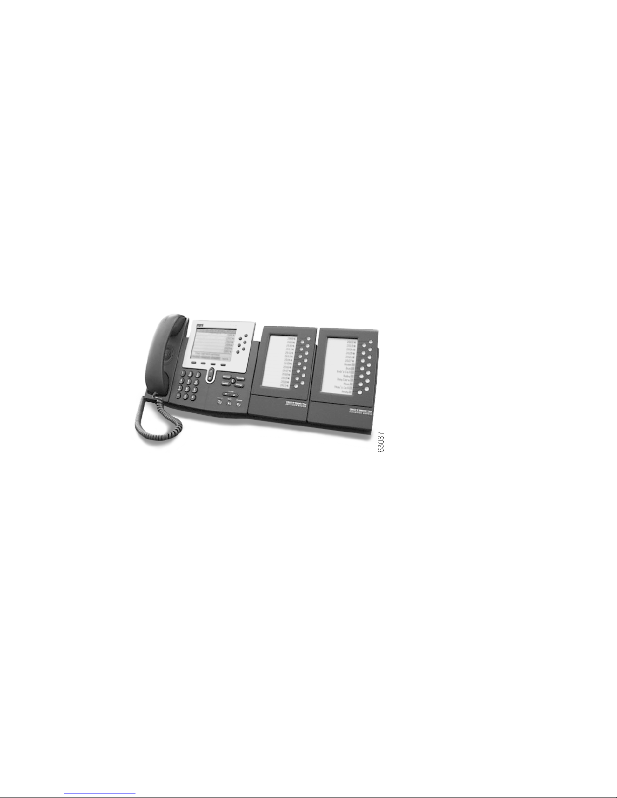
Installing the 7914 Expansion Module
Note To ensure a successful installation of the
7914 Expansion Module, make sure you have read the
entire “Before You Begin” section on page 3.
To install the 7914 Expansion Module, you need to perform the
following steps.
1. Remove the Footstand from the Cisco IP Phone 7960
2. Connect the Support Bar to the Cisco IP Phone 7960
3. Connect the 7914 Expansion Module to the Support Bar
4. Connect the RS 232 Cable
5. Connect the Power Supply
6. Connect the Footstand
Refer to the detailed instructions and corresponding
illustrations that follow for each of these high-level steps.
Caution To ensure a successful installation, verify with your
system administrator that your phone is ready for
the 7914 Expansion Module and that Cisco
CallManager is installed and configured for the
7914 Expansion Module. See the Cisco IP Phone
Administration Guide for Cisco CallManager for
more information. Make sure that you have all of
the parts that you need (see the “Before You Begin”
section on page 3).
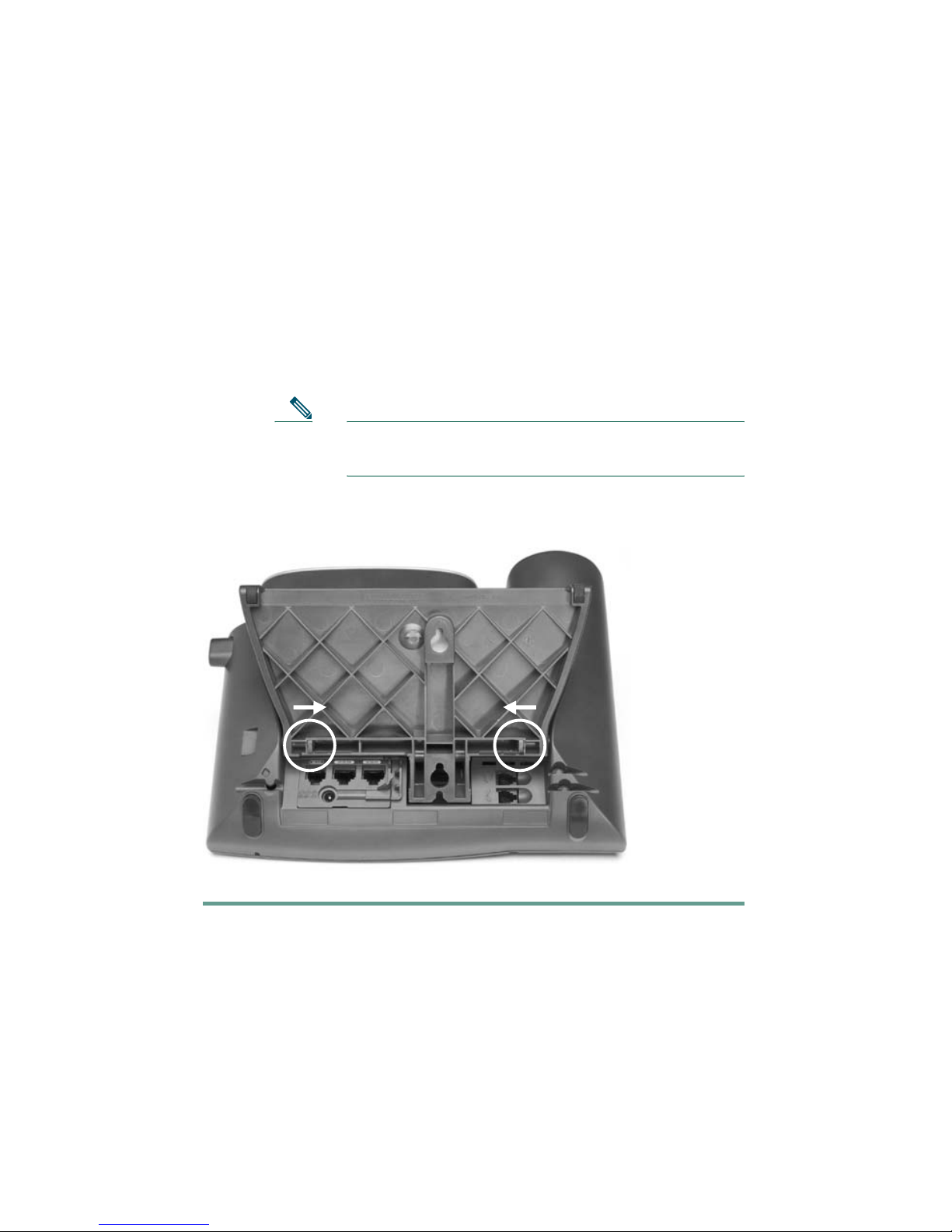
1. Remove the Footstand from the
Cisco IP Phone 7960
To remove the footstand from the IP Phone 7960 to which you
are attaching the 7914 Expansion Module, follow these steps.
Step 1 Unplug the Cisco IP Phone 7960 network and power
connections.