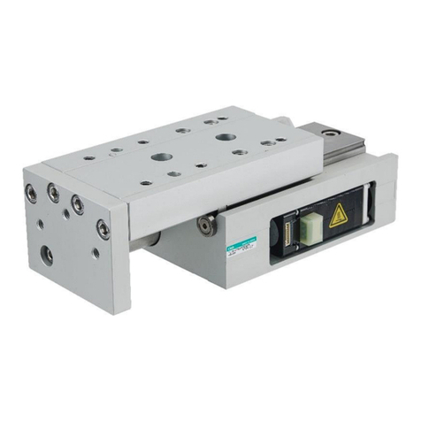
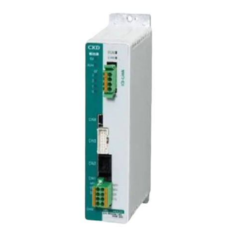
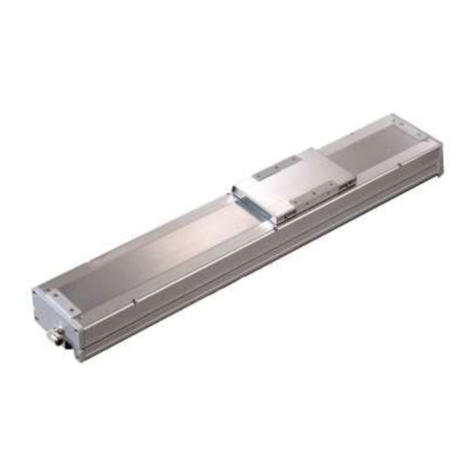
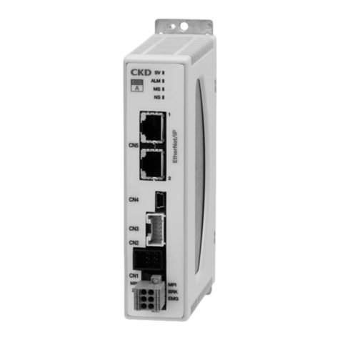
CKD KBZ Series User manual

INSTRUCTION
MANUAL
ELECTRIC ACTUATOR
KBZ Series
CONTROLLER
KCA-01-M05
ACTUATOR INSTRUCTION
MANUAL
●Read this manual carefully and thoroughly
before using thisproduct.
●Pay extra attention to the instructions
concerning safety.
●After reading this manual, keep it in a safe
and convenient place.
SM-479504-A
Discontinue

1
Introduction
Thank you for selecting the Electric Actuator KBZ series.
To ensure correct usage, read this instruction manual before starting use of the Electric
Actuator KBZ series.
For information on the actuators in Electric Actuator KBZ series, refer to the Actuator
Operating Manual supplied with the actuator.
PRECAUTION
1. The contents of this manual are subject to change without prior notice.
2. An effort has been made to ensure the contents of this manual.
If you have any questions, or find any mistakes, please contact CKD.
3. Regardless of item 2 above, CKD will not be held responsible for any
effect caused by using this actuator.
Discontinue

2
Contents
Chapter 1 General Safety Instruction ..............................................................................1
■1.1 Important Safety Information.................................................................................................... 1
■1.2 Safe Operation......................................................................................................................... 6
■1.2.1 Auxiliary safety precautions before robot installation ......................................................... 6
■1.2.2 Precautions for installing the robot ..................................................................................... 7
■1.2.3 Precautions for operation of the robot ................................................................................ 7
■1.3 Warranty................................................................................................................................... 9
■1.3.1 Warranty period .................................................................................................................. 9
■1.3.2 Warranty coverage.............................................................................................................. 9
■1.3.3 Disclaimers ......................................................................................................................... 9
■1.3.4 Notes................................................................................................................................. 10
Chapter 2 Overview.......................................................................................................11
■2.1 Features ................................................................................................................................. 11
■2.2 System Configuration............................................................................................................. 12
■2.3 Controller Specifications ........................................................................................................ 13
■2.4 External Dimensions .............................................................................................................. 14
■2.5 Names and Functions of Each Part ....................................................................................... 14
■2.5.1 Explanation of the controller ............................................................................................. 14
■2.5.2 Explanation of the teach pendant ..................................................................................... 20
■2.6 Connections ........................................................................................................................... 23
■2.7 Procedures from Installation to Operation ............................................................................. 24
■2.7.1 Selecting the power supply............................................................................................... 25
■2.7.2 Installing the controller ...................................................................................................... 26
■2.7.3 Supply power and grounding ............................................................................................ 27
■2.7.4 Power supply on/off timing................................................................................................ 28
■2.7.5 Improvement of noise resistance...................................................................................... 29
■2.7.6 Setting the robot type........................................................................................................ 30
■2.7.7 Servo gain adjustment ...................................................................................................... 32
■2.7.8 Resolver ABS backup....................................................................................................... 33
■2.8 Regenerative Resistors..........................................................................................................35
■2.8.1 Specifications.................................................................................................................... 35
■2.8.2 External dimensions.......................................................................................................... 36
■2.8.3 Installation......................................................................................................................... 36
■2.8.4 Connection example ......................................................................................................... 37
■2.9 Basic Knowledge ................................................................................................................... 39
■2.9.1 Let's begin moving the robot............................................................................................. 39
■2.9.2 Jog operation (axis operation in manual mode) ............................................................... 41
■2.9.3 Entering coordinate values ............................................................................................... 42
■2.9.4 Setting the override........................................................................................................... 45
■2.9.5 Initializing the memory ...................................................................................................... 45
■2.9.6 Monitor function ................................................................................................................48
■2.9.7 Turning on/off the teach pendant...................................................................................... 50
■2.9.8 Displaying the versions..................................................................................................... 51
Discontinue

3
Chapter 3 Parameter Settings .......................................................................................53
■3.1 Entering and Exiting the PARA Mode.................................................................................... 53
■3.2 Mode Setting.......................................................................................................................... 54
■3.2.1 M01 (T/P Japanese/English switching)............................................................................. 55
■3.2.2 M13 (OUT2 Function Selection) ....................................................................................... 55
■3.3 Parameter 1 ........................................................................................................................... 56
■3.3.1 P01 (+ Software limit) ....................................................................................................... 57
■3.3.2 P02 (- Software limit) ........................................................................................................ 57
■3.3.3 P03 (Servo Gain (Position)).............................................................................................. 58
■3.3.4 P04 (Servo Gain (Speed)) ................................................................................................ 58
■3.3.5 P05 (Origin Offset) ............................................................................................................ 59
■3.3.6 P06 (Jog Speed (Low))..................................................................................................... 60
■3.3.7 P07 (Jog Speed (High)) .................................................................................................... 60
■3.3.8 P08 (Jog Inching Value) ................................................................................................... 60
■3.4 Parameter 2 ........................................................................................................................... 61
■3.4.1 K01 (Axis Display)............................................................................................................. 63
■3.4.2 K02 (In-position Data)....................................................................................................... 63
■3.4.3 K03 (Overflow Data) ......................................................................................................... 64
■3.4.4 K04 (Rotation Direction).................................................................................................... 64
■3.4.5 K05 (Maximum Speed) ..................................................................................................... 65
■3.4.6 K06 (Low return home speed) .......................................................................................... 65
■3.4.7 K07 (Middle return home speed) ...................................................................................... 66
■3.4.8 K08 (High return home speed) ......................................................................................... 66
■3.4.9 K09 (Return home method) .............................................................................................. 68
■3.4.10 K10 (Home Sensor Logic) ................................................................................................ 69
■3.4.11 K11 (Fast return home target) .......................................................................................... 69
■3.4.12 K12 (Lead) ........................................................................................................................ 70
■3.4.13 K13 (Number of Sensor Divisions) ................................................................................... 70
■3.4.14 K14 (Multiplier).................................................................................................................. 71
■3.4.15 K15 (Sensor Type)............................................................................................................ 71
■3.5 Tables .................................................................................................................................... 72
■3.5.1 T01 (Point Table) .............................................................................................................. 73
■3.5.2 T02 (Speed Table) ............................................................................................................ 84
■3.5.3 T03 (Acceleration/Deceleration Table) ............................................................................. 85
■3.5.4 T04 (Torque Limit Table) .................................................................................................. 86
■3.5.5 T05 (Area Output Table)................................................................................................... 88
Chapter 4 Connection with External Devices ................................................................92
■4.1 Input/Output Signals .............................................................................................................. 92
■4.1.1 Input/output connector (CN4) signal names and pin numbers ......................................... 92
■4.1.2 Emergency stop input ....................................................................................................... 93
■4.1.3 System input ..................................................................................................................... 93
■4.1.4 System output ...................................................................................................................94
■4.1.5 Input/Output signal connection example........................................................................... 95
■4.2 System Input/Output Signals ................................................................................................. 96
■4.2.1 Start input (IN1)................................................................................................................. 96
■4.2.2 Stop input (IN2)................................................................................................................. 96
■4.2.3 Servo on input (IN3).......................................................................................................... 96
■4.2.4 Error reset input (IN5) ....................................................................................................... 98
Discontinue

4
■4.2.5 Operation/Teach switching input (IN6) ............................................................................. 98
■4.2.6 + Jog input, - Jog input (IN1, IN2)..................................................................................... 98

■4.2.7 Write input (IN4)................................................................................................................ 99
■4.2.8 Command point number input (IN7 - IN10)....................................................................... 99
■4.2.9 Output during operation (OUT1) ....................................................................................... 99
■4.2.10 Error output (OUT2) ........................................................................................................ 100
■4.2.11 READY/Error output (OUT2) .......................................................................................... 100
■4.2.12 Positioning complete output (OUT3)............................................................................... 101
■4.2.13 Area output (OUT4) ........................................................................................................ 101
■4.2.14 Completion point number output (OUT5 - OUT8)........................................................... 101
■4.2.15 Torque limit operation output (OUT5) ............................................................................. 102
■4.2.16 Load output (OUT6) ........................................................................................................ 102
■4.2.17 Limit output (OUT7) ........................................................................................................ 103
■4.2.18 Output during locking (OUT8)......................................................................................... 103
Chapter 5 Operation....................................................................................................104
■5.1 Normal Operation................................................................................................................. 104
■5.1.1 Moving to target position................................................................................................. 104
■5.1.2 Deceleration stop during movement ............................................................................... 105
■5.2 Torque Limit Operation ........................................................................................................ 107
■5.2.1 Ending torque limit operation by an external signal........................................................ 107
■5.2.2 Ending torque limit operation automatically.................................................................... 110
■5.3 Origin Return........................................................................................................................ 113
■5.4 Jog Operation....................................................................................................................... 114
■5.5 Writing Coordinate Values to the Point Table...................................................................... 116
Chapter 6 Errors..........................................................................................................117
■6.1 Error History Display ............................................................................................................ 119
■6.2 Error Code List..................................................................................................................... 120
Chapter 7 Maintenance and Inspection.......................................................................123
■7.1 Procedures Before and After Inspection and Maintenance ................................................. 123
■7.2 Inspection Before Operation ................................................................................................ 124
■7.3 Periodic Inspection............................................................................................................... 124
Discontinue

1
Chapter 1 General Safety Instruction
■1.1 Important Safety Information
To ensure safe usage of the Electric Actuator KBZ, read this Operating Manual before installation,
programming, operation, maintenance, and inspection.
After reading this manual, keep it in an easily accessible location, such as near this equipment, where it
can be referred to at all times.
Be sure to always follow the safety information to ensure safe usage of the
Electric Actuator KBZ.
The signal words below indicate important safety information and instructions displayed on this product
(controller) and in this operating manual for preventing injuries to the operator and others and property
damage and for ensuring safe usage of this equipment.
Be sure that you fully understand these signal words before reading the safety information.
WARNING
CAUTION
NOTE
This indicates a potentially hazardous situation which, if the displayed safety
information is not followed, could result in death or serious injury.
This indicates a potentially hazardous situation which, if the displayed safety
information is not followed, could result in injury or property damage
(extended damage to buildings, household furnishings, and domestic
animals and pets).
This provides a brief description of important points and notes about the
operating procedure for efficiently using this equipment.
The terminology description and reference page are instructed.
Discontinue

2
WARNING
•A safety fence must be installed to prevent entry into the range of motion of the
robot.
If a door or other entrance is provided in the safety fence, an emergency stop must be applied to
the robot when the door is opened.
•In case of emergencies, an emergency stop pushbutton switch must be
connected to the emergency stop input terminal of the controller and installed in
an easily accessible location.
The emergency stop pushbutton is designed so that it does not reset automatically and cannot
be unintentionally reset by the operator.
•All wiring work must be performed safely and in strict compliance with the
electrical equipment technical standards and internal wiring codes.
Improper wiring can result in an electric shock or fire.
•Do not repair or modify this equipment without permission of the manufacturer.
This can result in an accident or damage to this equipment.
•Be sure to ground this equipment before using.
Failure to ground this equipment can result in electric shock and increase the effects of electrical
noise.
•Before maintenance and inspection work, turn off the main power supply switch
to the controller and implement measures to prevent users other than the
operator engaged in the robot adjustment work from accidentally turning on the
power. (Lock-out and tag-out system)
Also, wait at least three minutes before touching the internal components of the
controller after the power is turned off.
An electric shock can occur due to the residual voltage in the capacitor.
•Do not touch the heatsink and cement resistors inside the controller or the
motor.
These components can become extremely hot, and a burn can result.
Before inspecting, be sure to wait sufficient time until the components cool down.
•Do not block the ventilation holes of this equipment.
Blocking the ventilation holes can cause heat to build up inside this equipment and can result in
a fire.
•Do not splash water in or outside this equipment, and do not wipe it with water
or other liquids.
This can result in an electric shock or breakdown of this equipment.
If this equipment is dirty, wipe off the dirt with a cloth that has been firmly wrung out.
Do not use thinners, benzene, or other organic solvents.
•Do not insert or drop metals, flammable items, or other foreign objects into the
machine from the ventilation holes.
This can result in a fire or electric shock.
Discontinue

3
CAUTION
•Do not insert your fingers or hands into the openings or moving parts.
This can result in an injury.
•When using the axis unit at an orientation other than the horizontal mounting, an
axis with brake must be used.
When the power is turned off, the slider can drop, and this can result in an injury.
•Perform regular checks on the brake functions of the axis with brake.
A failure in the brake can cause the slider to drop and result in an injury.
•During a power outage, either turn off the circuit breaker, or set this equipment
to emergency stop.
Otherwise, the axis can move suddenly when the power is restored, and this can result in an
injury or damage to the product.
•This product is heavy. When transporting it, check its weight and center of
gravity before releasing the cables and carrying it.
Also, do not grasp the sliders to take out this equipment when transporting it.
The sliders can move and result in an injury.
•Do not use this equipment as a massage machine or for other applications on
living subjects.
A programming error or operation mistake can result in an injury.
•This equipment does not have an airtight structure.
During usage, ball screw grease and dust from belt wear can spray out from the
openings.
If using for applications in food processing or pharmaceuticals, be sure to implement measures
to prevent mixing with these substances.
•Do not put the battery or electrolytic capacitor in a fire.
This can result in an explosion.
•Mount the supplied terminal block cover to the power supply terminal block.
If the cover is not mounted, an electric shock can occur when touching the terminal block.
•Be sure to correctly enter the robot type and perform memory initialization.
Entering the wrong robot type and improper memory initialization can cause the robot to move in
an unexpected direction and result in an injury.
•Do not use this equipment in an environment where a flammable gas or
explosive atmosphere is present.
This equipment does not have an explosion-proof structure, and so an explosion can result.
•Do not damage, destroy, forcibly bend or pull, or place heavy objects on the
cables (power supply cables, controller cables, axis connection cables, and
flexible duct cables), or squeeze objects in between the cables.
This can result in a fire, electric shock, or damage to this equipment.
•If smoke or an unusual smell is coming out from this equipment, or if another
abnormal situation occurs, immediately turn off the power, and stop usage.
Continuing to use this equipment can result in a fire or electric shock.
Discontinue

4
CAUTION
•When using the motor reversal axis in a vertical orientation, perform periodic
inspection of the belt, and replace the belt after every 3000 hours of operation.
If the belt is used past its lifespan, it can break. This could cause the slider to unexpectedly drop,
and result in an injury.
•Do not install this equipment in a location where the ambient temperature
exceeds 40°C, where this equipment is subject to extreme variations in
temperature that could cause condensation, or where this equipment is exposed
to direct sunlight.
Also, if this equipment is installed in a confined location, heat can build up in the controller itself
and the external devices, causing the ambient temperature to rise, and result in a breakdown or
malfunction of this equipment.
•Do not use in locations exposed to heavy shocks or vibrations.
Also, do not use in environments where conductive dust, corrosive gas, oil, and
other mist are present.
This can result in a fire, electric shock, breakdown, malfunction, or other problems.
•Do not use in locations with large amounts of dust.
This equipment does not have a dust-proof structure, and this can result in a breakdown.
•Use only manufacturer-authorized parts for repair.
Usage of non-authorized parts can not only reduce this equipment performance, but can also
result in a breakdown.
•Use an object with sufficient rigidity for the robot body installation frame.
If the frame does not have sufficient rigidity, vibrations (resonance) can occur during robot
operation and adversely affect the work.
•In the event of a power outage, this equipment will run freely. Therefore, use an
axis with brake even when using a horizontal axis if there is a possibility of
damage to the machines or workpieces.
This machine does not include a dynamic brake system.
•Turn off the control power supply and drive power supply one second or more
after the servo lock is freed.
Failure to observe this timing can cause the vertical axis to drop by up to about 5 mm.
•Do not insert or remove the connectors when the controller power is turned on.
This can result in a breakdown or malfunction of the controller.
•Implement safety protection for dropping or flying out of workpieces.
A collision can cause a sudden deceleration of the axis and cause a workpiece to drop or fly out.
•Perform a risk assessment on the entire equipment, and implement any
necessary safety measures.
•Properly dispose of this product as an industrial waste product.
Discontinue

5
Warning labels are affixed to the product body for particularly important safety information.
Please make sure the labels do not come off or become illegible.
Controller warning label
WARNING
•To ensure safety, be sure to read the Operating Manual before installation, programming,
operation, maintenance, and inspection.
•Before maintenance and inspection work, turn off the main power supply switch to the
controller and implement measures to prevent users other than the operator engaged in the
robot adjustment work from accidentally turning on the power.
Also, wait at least three minutes before touching the internal components of the controller
after the power is turned off.
An electric shock can occur due to the residual voltage in the capacitor.
•A safety fence must be installed to prevent entry into the range of motion of the robot.
•In case of emergencies, an emergency stop pushbutton switch must be connected to the
emergency stop input terminal of the controller and installed in an easily accessible location.
•Be sure to ground this equipment before using.
Failure to ground this equipment can result in electric shock and increase the effects of
electrical noise.
•Never modify this equipment.
Axis warning label
<IMPORTANT>
WARNING
•To ensure safety, be sure to read the Operating Manual before
installation, programming, operation, maintenance, and inspection.
•A safety fence must be installed to prevent entry into the range of
motion of the robot.
•Do not insert your fingers or hands into the openings or moving parts.
This can result in an injury.
•When using at an orientation other than the horizontal mounting, an
axis with brake must be used. When the power is turned off, the slide
r
can drop, and this can result in an injury.
Discontinue

6
■1.2 Safe Operation
When using the Electric Actuator KBZ series, safety measures must be implemented to satisfy the items
below. This equipment corresponds to an industrial robot as stipulated in article 36, item 31 of the
Occupational Safety and Health Act regulations. Important safety information when using this equipment is
contained in the sections "Selection", "Installation", "Usage", "Periodic Testing", and "Training" in the
"Technical Guidelines for Safety Standards in Usage of Industrial Robots" based on article 28 of the
Occupational Safety and Health Act. First, read this information carefully, and then implement the
necessary measures. A portion of this safety information is presented below.
■1.2.1 Auxiliary safety precautions before robot installation
(1) Install a safety fence to prevent people from entering the area of robot operation.
1. The fence should be strong enough to withstand any force
it might be expected to encounter during normal Robot or
other operations. It should not be easy to breach, climb
over or move.
2. It should be constructed of safe material with no sharp
edges.
3. The foundation should be rigid and immobile.
4. Any door on the fence must be interlocked with the robot
so that robot operations stop automatically when the door
is opened.
(2) Install an emergency stop device in an easily accessible place to enable an operator to quickly stop
the robot in case of an emergency.
1. When an emergency stop switch is operated the braking
device must stop the robot quickly without fail.
2. The emergency stop button should be red.
3. The activating device must be readily acces sible so the
operator can easily trigger it by, for example, pressing,
pulling, or touching a switch or by blocking a light beam.
4. Once triggered, the emergency stop device must be
restorable only through deliberate action of an operator. It
must not allow operations to be resumed automatically or
through inattention on the part of an operator.
(3) No alteration or modification of the products is allowed.
Keep out
Emergency
stop button
Keep out
Discontinue

7
■1.2.2 Precautions for installing the robot
Pay attention to the following points when installing the robot.
(1) Allow ample clearance for teaching the robot, maintenance operations and inspection.
(2) The robot controller, other control devices must be installed outside the robot's zone of operation, but
within easy access of the operator.
(3) The pressure gauge, oil pressure gauge and other indicators must be located so the operator can
monitor them easily.
(4) Cover electric cables, oil hydraulic lines and pneumatic pipe lines when necessary to protect them
from damage.
(5) Install an emergency stop switch at appropriate locations other than the operator's station to use in
the emergency situation.
■1.2.3 Precautions for operation of the robot
Pay attention to the following points when operating the robot.
[Operation inside the actuator operating area]
(1) Safety regulations for personnel working in the actuator's operating area
Safety regulations for personnel working in the actuator's operating area should include, but not be
limited to, the following:
1. Basic robot operations such as starting, stopping and switch handling.
2. Robot speed during teaching procedures.
3. Communications, including signals, among operators when the robot is operated by more than
one person.
4. Emergency procedures to be taken for malfunctions or abnormal operations of the robot.
5. Procedures to be taken for verifying recovery from abnormal conditions and confirming safety
conditions before restarting the robot after it is stopped by an emergency stop device.
6. Procedures to be taken to prevent accidents caused by inattentive operation or mishandling of
the robot.
•Notices on the operator's station.
•Precautions as needed to assure the safety of personnel in the robot's area of operation.
•The exact location of personnel during work.
•Procedures to be taken to prevent malfunctions arising from electrical noise.
•Communications, including signals, between personnel in the actuator operation area and
operators of robot and other devices.
•Procedures to determine the cause of a malfunction.
7. The safety regulations must be appropriate for the robot type, installation place and work details,
etc.
8. When creating the safety regulations, an effort should be made to obtain the opinions of the
related personnel, manufacturer's engineers and labor safety consultants, etc.
(2) Notices on the operator's station
Install notices on robot switches to alert personnel that work is underway in the robot operation area
and lock the cover to the operator's station.
Discontinue

8
(3) Precautions as needed to assure the safety of personnel in the robot's area of operation
To secure the zone of robot operation, take measures such as but not limited to the following.
1. Assign a guard to watch the robot operating area to prevent unauthorized persons from entering
the operating zone. The guard should be trained to activate emergency stop devices.
2. Personnel working inside the operating zone should carry emergency stop switches.
3. The operator should use a portable operator's station that can be used to turn ON or OFF power
to the robot, oil pressure devices, and pneumatic devices.
(4) Pre-operation inspections before teaching or other operations
Make the following inspections before teaching or other operations, and take the measures:
1. Turn the power switch OFF, and check the external power supply for damage.
2. Test the actuator to make sure it moves properly.
3. Inspect the control devices and emergency stop devices.
4. Check for leakage in pneumatic pressure lines and hydraulic oil lines.
(5) Cleaning of tools
Procedures for cleaning robot hand tools, such as paint spray nozzles, should be automated so
operators do not have to enter the actuator's operating area.
(6) Releasing of residual pressure
Release residual pressure before disassembling or changing parts in a pneumatic system.
(7) Operation for confirmatioin
Do not enter the actuator's operating area zone to confirm proper operation.
(8) Illuminance
Maintain proper lighting at the work site.
[Automatic operation]
(1) Notice at the start
Before beginning operation, confirm the following items and confirm communication procedures
including hand signals among operators.
1. Make sure no one is inside the actuator operating area.
2. Portable operator stations, tools and devices are located at their assigned sites.
3. Indicators on the robot and auxiliary devices are normal.
(2) Procedures for automatic operation and malfunctions
1. After start, confirm that the indicator shows automatic operation is underway.
2. Before personnel enter the robot's zone of operation to recover the robot or related devices from
a malfunction, the operator must activate the emergency stop device and attach an "under
repair" message to operation switches and take other measures to prevent others from starting
the robot.
Discontinue

9
■1.3 Warranty
■1.3.1 Warranty period
The warranty period of the product is one of the periods below, whichever is reached first.
(1) 12 months after CKD factory shipping
(2) 4000 hours of operation
■1.3.2 Warranty coverage
(1) This warranty covers this product. The scope of the warranty applies to the specifications and
functions of this product that were stipulated in the specifications, catalog, instruction manual, and
other documentation. CKD will not be liable for any secondary or incidental damage as a result of
breakdowns of this product.
(2) During the warranty period of this product, CKD will repair free of charge only breakdowns that occur
for operation and usage performed in accordance with the instruction manuals provided with the
product. Repairs will entail the return of the product to the factory. However, if service staff are sent or
other measures taken based on the customer’s specific circumstances, CKD reserves the right to
invoice separately for transportation and lodging costs and for costs arising not directly related to
product repair.
■1.3.3 Disclaimers
The cases below are outside the scope of the warranty.
(1) Breakdowns and damage due to failure to use in accordance with the instruction manual or failure to
pay attention during operation
(2) Nonconformity due to the passage of time or usage wear (such as natural fading of paint and
degradation of consumable parts*1)
(3) Nonconformity in sensory conditions (such as the occurrence of noises not affecting functionality)
(4) When modifications or disassembly was performed without the authorization of CKD
(5) Breakdowns or damage due to inadequate maintenance or inspection or improper repairs
(6) Breakdowns and damage due to natural disasters, fires, or other external causes
(7) Programs, points, and other internal data that was created or modified by the customer
(8) When this product was purchased in Japan and taken outside the country
*1):Consumable parts refer to the maintenance and replacement parts (spare parts) and the parts that
must be replaced periodically (such as backup batteries) shown in the instruction manual of each
product.
Discontinue

10
■1.3.4 Notes
(1) CKD cannot guarantee basic performance of this product when it is used under conditions outside the
product specifications.
(2) CKD is not liable for any accidents, damage, or breakdowns that occur as a result of failing to follow
the warning and caution information provided in this instruction manual.
(3) The warning and caution information and other descriptions provided in this manual do not cover
every possible situation imaginable.
(4) The numerical values presented in the technical documentation were derived from calculations and
are intended to serve as a reference for durability and do not constitute a warranty of any kind.
Differences will arise based on the specific usage conditions.
Discontinue

11
Chapter 2 Overview
■2.1 Features
This product is a single-axis robot controller with 24 V DC power supply that has been developed for
providing a powerful features in a compact, low-cost design.
The main features and functions are shown below.
[Features of Axis Unit]
Motor sensor with built-in resolver
The motor sensor incorporates a brushless resolver as standard for providing superior resistance to
environmental conditions (high and low temperatures, vibrations, impact). This reduces the possibility
of breakdowns under adverse operating conditions.
Compact, high-output servo motor
A compact servo motor is used to enable high speed, high acceleration/deceleration, and high weight
capacities. The high-speed performance enables reduced device cycle times.
Absolute encoder support
This eliminates the need for troublesome origin return operations for shorter device startup times.
[Features of Controller]
Program-free operation
The desired operation can be performed by simply setting the parameters and tables. Because there is
no need to learn any complicated programming languages, this enables shorter system startup times
and greater ease of maintenance.
Includes torque limit function as standard, making it ideal for pressing against workpieces
Workpiece pressing operations, which required frequent use of the air cylinder before, can now be
performed by the robot using the new torque limit function. This enables coordinated usage with regular
positioning control for realizing energy savings and higher efficiency.
Simple teaching
Functions are provided for jog operation and writing of the current position to the point table using
system input signals only. Because teaching is possible without a computer or teach pendant, this
simplifies the process of fine adjustment on-site and enables greater ease of maintenance.
Greater range of expression
A three-color LED is used to indicate detailed information about the controller state. In particular, when
an error occurs, the error code is indicated by the number of flashes by the LED for enabling quick
assessment of the problem situation and shortening the time required for recovery.
Individual settings for acceleration and deceleration
The acceleration and deceleration can now be set individually. This enables shorter tact times by
allowing the setting of faster acceleration even in applications where slower deceleration is required.
Brake release switch provided as standard
A brake release switch is included on the front of the controller.
Discontinue

12
■2.2 System Configuration
センサ
モータ
回生抵抗
駆動電源
制御電源
KBZ axis
Teach pendant
or
Computer
Sequencer and
other devices
Sensor Motor
View from Arrow A
Drive power supply
Regenerative resistor
Control power supply
Battery
Discontinue

13
■2.3 Controller Specifications
Item Description
Compatible robot Electric Actuator KBZ series
Controller model KCA-01-M05
Number of controllable axes 1 axis
Motor capacity 50 W
Control method Semi-closed loop control
Teaching method Remote teaching, Direct teaching or MDI
Speed setting 8 steps (variable)
Acceleration/deceleration setting 8 steps (variable)
Number of point tables 15 tables
Recording method EEPROM (limit of 1 million rewrites)
Movement mode Point mode
Special functions Torque limit function
Emergency stop input Included
Origin sensor input Included
Regenerative function Included (with external regenerative resistor mounted)
Dynamic brake function None
Mechanical brake drive output 24 V DC -0.4 A or less (for non-excitation operation holding brake)
Manual reset is possible by Brake Release Switch (SW1)
Hardware errors Sensor error, Drive power supply error, Non-volatile memory error, Overheat error, and more
Software errors Overspeed, Overload, Positional deviation exceeded and more
Protective
functions
Warnings Drive power supply shut off, Low battery voltage
Status indicators
Status LED (LED1) indicators
•Normal mode (SW2 is set to 0)
Servo OFF : Green (solid) Servo ON : Green (flashing)
Drive power OFF : Orange (solid) Low battery voltage : Orange (flashing)
Power supply shutoff request : Red (solid) Error : Red + Green (flashing)
•Boot mode (SW2 is set to F)
Normal end : Green (solid) Abnormal end : Red (solid)
Boot standby : Red + Green (flashing) Boot in progress : Red + Green (flashing)
System input 24 V 7 mA 10 inputs
System output 30 V max. 100 mA max. 8 outputs
Communication function RS-232C 1 channel (9600 bps)
For teach pendant, computer software (SF-98D)
Control power supply voltage 24 V DC ±10%
Drive power supply voltage 24 V DC ±10%
Control power supply capacity 0.25 A
Drive power supply capacity Based on axis model. Rating 3 A (Max. 9 A)
Operating temperature
range 0 to 40°C
Operating humidity
range 90% max. (no condensation)
Storage temperature
range -10 to 85°C
Storage humidity range 90% max. (no condensation)
Environment
Indoor (not exposed to direct sunlight), maximum altitude of 1000 m,
location not exposed to dust, dirt, corrosive gases, or flammable
gases
Environmental conditions
Vibrations/Impact 4.9 m/s2max. / 19.6 m/s2max.
Dimensions 31(W)
×146(H) ×89(D) (not including screw protrusions)
Weight Approx. 0.25 kg
Discontinue

14
■2.4 External Dimensions
■2.5 Names and Functions of Each Part
■2.5.1 Explanation of the controller
SW1 brake
r
elease switch
LED1 status LED
SW2 mode setting switch
CN3 sensor connecto
r
CN5 serial connecto
r
CN4 in
p
ut/out
p
ut connecto
r
CN1
p
ower connecto
r
CN2 motor connecto
r
CN6 batter
y
connecto
r
A
View from Arrow A
Discontinue

15
CN6 battery connector
This is a connector for connecting the resolver ABS backup battery.
For details on the battery connector, refer to section ■2.7.8.
SW1 brake release switch
This is a momentary switch for manually releasing the brake.
The brake is manually released while the lever is raised to the up position, and the brake returns to
normal brake control when the lever is released.
CAUTION Use caution when manually releasing the brake. It could drop suddenly, resulting
in damage to the workpiece or robot hand or entanglement of the operator’s hand.
LED1 status LED
This uses three colors to indicate the controller status.
I. Normal mode (SW2 is set to 0)
Priority Color Status 1 Status 2 Flashing
pattern
High Flashing red + green
Error detected
Error code: Flashes red to indicate value of tens
digit. Flashes green to indicate value of ones digit
↓Solid red Power supply shutoff request (*1) −
↓Flashing orange Low battery voltage (*2)
↓Solid orange Drive power supply OFF −
↓Solid green Servo OFF Drive power supply ON −
Low Flashing green Servo ON
(*1) If this status occurs, shut off the control power supply and drive power supply.
(*2) This is enabled when the sensor type is set to 1 (refer to section ■3.4.15).
ON
OFF
0.4 sec
Flashing pattern
Example 1: Error code 42
tens digit: No. of red flashes
Red 4 times
ones digit: No. of
green flashes
Repeats continuously
ON
OFF
0.4 sec
Example 2: Error code 102
tens digit: No. of red flashes
Red 10 times
ones digit: No. of
green flashes
Repeats continuously
Green 2 times
Green 2 times
Discontinue
Other manuals for KBZ Series
1
Table of contents
Other CKD Controllers manuals
Popular Controllers manuals by other brands

Omron
Omron 61F-D21T-V1 datasheet

MKS
MKS Granville-Phillips 358 series instruction manual

MR
MR VACUTAP VM Series operating instructions

Kuppersbusch
Kuppersbusch EKE 8752.0 Service manual

amiad
amiad ADI-P Installation, operation and maintenance instructions

Homematic IP
Homematic IP HmIP-BBL-2 Installation instructions and operating manual

Chauvet
Chauvet Tiger DMX 60 user manual

Parker
Parker A4AT-DN Installation and Service Information

Whelen Engineering Company
Whelen Engineering Company Wireless Traffic Advisor Installation guides

AuCom
AuCom CSX-007 Service manual

Linak
Linak TECHLINE LA36 Connection diagram

Rosewill
Rosewill RC215 user manual