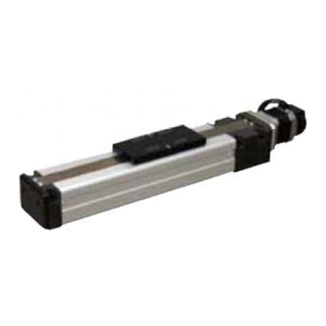
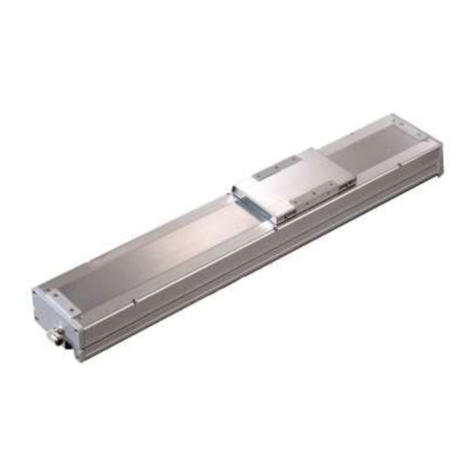
CKD ERL2 Series User manual

INSTRUCTION MANUAL
INSTRUCTION MANUAL
•Read this Instruction Manual before using the product.
•Read the safety notes carefully.
•Keep this Instruction Manual in a safe and convenient place for future reference.
SM-612226-A/4
MSV-484083
Electric Actuator
ERL2 Series (Slider Type)
ESD2 Series (Rod Type)

SM-612226-A/4 PREFACE
i 2018-11-12
PREFACE
Thank you for purchasing CKD's "ERL2 Series/ESD2 Series" electric actuator.
This Instruction Manual contains basic matters such as installation and usage instructions in order to
ensure optimal performance of the product. Please read this Instruction Manual thoroughly and use the
product properly.
Keep this Instruction Manual in a safe place and be careful not to lose it.
Product specifications and appearances presented in this Instruction Manual are subject to change
without notice.
•The product, which uses control valves such as solenoid valves, motor valves, and air operated
valves, is intended for users who have basic knowledge about materials, fluids, piping, and
electricity. CKD shall not be responsible for accidents caused by persons who selected or used the
product without knowledge or sufficient training with respect to control valves.
•Since there are a wide variety of customer applications, it is impossible for CKD to be aware of all of
them. Depending on the application or usage, the product may not be able to exercise its full
performance or an accident may occur due to fluid, piping, or other conditions. It is the responsibility
of the customer to check the product specifications and decide how the product shall be used in
accordance with the application and usage.

SM-612226-A/4 SAFETY INFORMATION
ii 2018-11-12
SAFETY INFORMATION
When designing and manufacturing any device incorporating the product, the manufacturer has an
obligation to ensure that the device is safe. To that end, make sure that the safety of the machine
mechanism of the device and the electric system that controls such mechanism is ensured.
In order to use our products safely, it is important to select, use, handle, and maintain the products
properly.
Observe the warnings and precautions described in this Instruction Manual to ensure device safety.
Although various safety measures have been adopted in the product, customer's improper handling may
lead to an accident. To avoid this:
Thoroughly read and understand this Instruction Manual
before using the product.
To explicitly indicate the severity and likelihood of a potential harm or damage, precautions are classified
into three categories: "DANGER", "WARNING", and "CAUTION".
DANGER
Indicates an imminent hazard. Improper handling will cause death or serious
injury to people.
WARNING
Indicates a potential hazard. Improper handling may cause death or serious
injury to people.
CAUTION
Indicates a potential hazard. Improper handling may cause injury to people or
damage to property.
Precautions classified as "CAUTION" may still lead to serious results depending on the situation.
All precautions are equally important and must be observed.
Other general precautions and tips on using the product are indicated by the following icon.
Indicates general precautions and tips on using the product.

SM-612226-A/4 SAFETY INFORMATION
iii 2018-11-12
Precautions on Product Use
DANGER
Do not use the product for the following applications:
•Medical equipment pertaining to sustainment and management of human life and body
•Mechanism and mechanical device for transferring and transporting people
•Critical parts for securing safety in a mechanical device
WARNING
Use the product within the specifications.
Precautions on Product Disposal
CAUTION
When disposing of the product, comply with laws pertaining to disposal and cleaning of
wastes and have an industrial waste disposal company dispose of the product.

SM-612226-A/4 CONTENTS
iv 2018-11-12
CONTENTS
PREFACE........................................................................................................................... i
SAFETY INFORMATION.................................................................................................. ii
Precautions on Product Use..........................................................................................iii
Precautions on Product Disposal ..................................................................................iii
CONTENTS...................................................................................................................... iv
1. PRODUCT OVERVIEW............................................................................................. 1
1.1 System Overview................................................................................................1
1.1.1 System structure........................................................................................... 1
1.2 Part Name........................................................................................................... 2
1.2.1 ERL2 Series (slider type)............................................................................. 2
1.2.2 ESD2 Series (rod type) ................................................................................ 2
1.2.3 Motor/encoder relay cable (EC-CBLME 1) .................................................. 3
1.3 Model Number Indication....................................................................................4
1.3.1 ERL2 Series (slider type)............................................................................. 4
1.3.2 ESD2 Series (rod type) ................................................................................ 5
1.3.3 ERL2 Series (slider type) optional parts ...................................................... 6
1.3.4 ESD2 Series (rod type) mounting brackets.................................................. 7
1.4 Specifications...................................................................................................... 8
1.4.1 Product specifications .................................................................................. 8
1.4.2 Correlation between the speed and the load capacity.................................9
1.4.3 Correlation between the pressing force and
the pressing current setting value...............................................................11
1.5 Dimensions....................................................................................................... 12
1.5.1 ERL2-45E (Standard (straight)) ................................................................. 12
1.5.2 ERL2-45R (Rightward)............................................................................... 13
1.5.3 ERL2-45L (Leftward).................................................................................. 14
1.5.4 ERL2-45D (Downward).............................................................................. 15
1.5.5 ERL2-60E (Standard (straight)) ................................................................. 16
1.5.6 ERL2-60R (Rightward)............................................................................... 17
1.5.7 ERL2-60L (Leftward).................................................................................. 18
1.5.8 ERL2-60D (Downward).............................................................................. 19
1.5.9 ESD2-35E (Standard (straight))................................................................. 20
1.5.10 ESD2-35R (Rightward)............................................................................... 21
1.5.11 ESD2-35L (Leftward).................................................................................. 22
1.5.12 ESD2-35D (Downward).............................................................................. 23
1.5.13 ESD2-45E (Standard (straight))................................................................. 24
1.5.14 ESD2-45R (Rightward)............................................................................... 25
1.5.15 ESD2-45L (Leftward).................................................................................. 26
1.5.16 ESD2-45D (Downward).............................................................................. 27
1.5.17 ESD2-55E (Standard (straight))................................................................. 28
1.5.18 ESD2-55R (Rightward)............................................................................... 29
1.5.19 ESD2-55L (Leftward).................................................................................. 30
1.5.20 ESD2-55D (Downward).............................................................................. 31
2. INSTALLATION ....................................................................................................... 32
2.1 Environment......................................................................................................34
2.2 Unpacking.........................................................................................................35
2.2.1 Parts of the product.................................................................................... 35
2.3 Installing............................................................................................................ 36
2.3.1 ERL2 Series (slider type)........................................................................... 36
2.3.2 ESD2 Series (rod type) .............................................................................. 37
2.3.3 Objects Transferred.................................................................................... 38

SM-612226-A/4 CONTENTS
v 2018-11-12
3. USAGE..................................................................................................................... 42
3.1 Safety Instructions ............................................................................................42
4. MAINTENANCE AND INSPECTION....................................................................... 44
4.1 Periodic Inspection............................................................................................45
4.1.1 Inspection item ........................................................................................... 45
4.1.2 Recommended grease............................................................................... 46
4.1.3 Recommended grease gun........................................................................ 46
4.1.4 ERL2 Series (slider type) greasing procedure........................................... 47
4.1.5 ESD2 Series (rod type) greasing procedure.............................................. 49
4.1.6 Replacement and adjustment procedures for the timing belt.................... 50
5. TROUBLESHOOTING............................................................................................. 52
5.1 Items to Check When a Problem Occurs.........................................................52
5.2 Problems, Causes, and Solutions .................................................................... 53
5.3 Alarm Code....................................................................................................... 55
6. WARRANTY PROVISIONS..................................................................................... 57
6.1 Warranty Conditions .........................................................................................57
6.2 Warranty Period................................................................................................ 57
6.3 Remarks............................................................................................................57

SM-612226-A/4 1. PRODUCT OVERVIEW
1 2018-11-12
1. PRODUCT OVERVIEW
1.1 System Overview
1.1.1 System structure
Devices indicated with an asterisk (*) are not supplied with the product.
Item
Part name
Product name/Model no.
Standard structure
(when a set model number
is selected)
Controller
EC07/EC63/ECPT
Actuator
ERL2/ESD2 Series
I/O cable
EC-CBLIF1
Motor/encoder relay cable
EC-CBLME1
Sold separately
Teaching pendant
ETP2
Computer communication cable
EC-CBLPC2
Surge protector
AX-NSF-RAV-781BXZ-4
Noise filter
AX-NSF-NF2015A-0D
Provided for free
Software for Windows
E Tools
PLC*
Surge protector
AX-NSF-RAV-781BXZ-4
(sold separately)
Power*
24 VDC
power*
Noise filter
AX-NSF-NF2015A-0D
(sold separately)
Controller
EC07
EC63
ECPT
I/O cable
EC-CBLIF1
Teaching pendant
ETP2
(sold separately)
Computer
communication cable
EC-CBLPC2
(sold separately)
Software for Windows
E Tools
(provided for free)
RS485 interface*
Computer*
Motor/encoder relay cable
EC-CBLME1
ERL2 Series
ESD2 Series
Actuator

SM-612226-A/4 1. PRODUCT OVERVIEW
2 2018-11-12
1.2 Part Name
1.2.1 ERL2 Series (slider type)
1.2.2 ESD2 Series (rod type)
Steel tape
Slider
Motor
section
Opposite side of the motor
Motor side
Slider body
Connection
plate
Rod
Body
Connection
plate
Motor section
Spacer (option)
Motor side
Opposite side of the motor

SM-612226-A/4 1. PRODUCT OVERVIEW
3 2018-11-12
1.2.3 Motor/encoder relay cable (EC-CBLME 1)
Fixed type
Model no.
Cable length (L)
EC-CBLME1-S-1
1 m
EC-CBLME1-S-3
3 m
EC-CBLME1-S-5
5 m
EC-CBLME1-S-X
10 m
Movable type
Model no.
Cable length (L)
EC-CBLME1-R-1
1 m
EC-CBLME1-R-3
3 m
EC-CBLME1-R-5
5 m
EC-CBLME1-R-X
10 m
L (The cable length depends on the model no.)

SM-612226-A/4 1. PRODUCT OVERVIEW
4 2018-11-12
1.3 Model Number Indication
1.3.1 ERL2 Series (slider type)
Set model number (actuator, controller, and cable)
Model
[A] Body size
[C] Screw lead
[D] Stroke
[F] Origin position
[H] Controller
[I] I/O cable length
[E] Brake
<Example of model number indication>
[A] Body size : 60
[B] Motor mounting : Standard
direction (straight)
[C] Screw lead : 6 mm
[D] Stroke : 500 mm
[E] Brake : With brake
[F] Origin position : Motor side
[G] Relay cable length : Movable cable 10 m
[H] Controller : EC07 DIN rail mount
[I] I/O cable length : 2 m
Actuator model number
[A] Body size
[C] Screw lead
[D] Stroke
[E] Brake
[F] Origin position
[A] Body size
[C] Screw lead
Symbol
Description
Body size 45
Body size 60
[D] Stroke
Body size/Motor mounting direction
[E] Brake
Without brake
With brake
Motor side
Opposite side of the motor
[F] Origin position
[G] Relay cable length
None
Fixed cable 1 m
Fixed cable 3 m
Fixed cable 5 m
Fixed cable 10 m
Movable cable 1 m
Movable cable 3 m
Movable cable 5 m
Movable cable 10 m
[I] I/O cable length
[H] Controller
None
Standard mount
Standard mount
DIN rail mount
DIN rail mount
[B] Motor mounting direction
[G] Relay cable length
[B] Motor mounting direction
Standard (straight)
Rightward
Leftward
Downward
Symbol
Length
Standard mount
DIN rail mount
Note 1
Note 2
Note 2
None
Note 3
Note 3
[B] Motor mounting direction
Cable model number
Mounting method
Series
Cable length
Controller series
Fixed/Movable
Cable length
Relay cable
I/O cable
6 mm
12 mm
50 mm
100 mm
150 mm
200 mm
250 mm
300 mm
350 mm
400 mm
450 mm
500 mm
550 mm
600 mm
700 mm
2 m
3 m
5 m
Note 1: If selecting “N” for controller, also select “N” for I/O cable length.
Note 2: Use PLC unit which satisfies the ECPT pulse string signal input specifications (refer to
pages 5 to 13 in “SM-612271 Controller Instruction Manual”).
Note 3: If the controller is E or F, these cables can be used only when the differential system is
used as the pulse string signal system.
Only the 2 m cable can be used for the open collector system.

SM-612226-A/4 1. PRODUCT OVERVIEW
5 2018-11-12
1.3.2 ESD2 Series (rod type)
Set model number (actuator, controller, and cable)
Model
[A] Body size
[C] Screw lead
[D] Stroke
[F] Origin position
[H] Controller
[I] I/O cable length
[E] Brake
<Example of model number indication>
Actuator model number
[A] Body size
[C] Screw
lead
[D] Stroke
[E] Brake
[F] Origin
position
[A] Body size
[C] Screw lead
Symbol
Description
[D] Stroke
Body size
[E] Brake
[F] Origin position
[G] Relay cable length
[I] I/O cable length
[H] Controller
Note 1: If selecting “N” for controller, also select “N” for I/O cable length.
Note 2: Use PLC unit which satisfies the ECPT pulse string signal input specifications (refer to
pages 5 to 13 in “SM-612271 Controller Instruction Manual”).
Note 3: If the controller is E or F, these cables can be used only when the differential system is
used as the pulse string signal system.
Only the 2 m cable can be used for the open collector system.
Standard mount
Standard mount
DIN rail mount
DIN rail mount
[B] Motor mounting direction
[G] Relay cable length
[B] Motor mounting direction
Standard (straight)
Rightward
Leftward
Downward
Symbol
Standard mount
DIN rail mount
Note 1
Note 2
Note 2
2 m
3 m Note 3
5 m Note 3
[B] Motor
mounting
direction
Controller model number
Cable model number
Mounting method
Series
Cable length
Controller series
Fixed/Movable
Cable length
Relay cable
I/O cable
[J] Mounting bracket
[A] Body size : 55
[B] Motor mounting : Standard
direction (straight)
[C] Screw lead : 12 mm
[D] Stroke : 50 mm
[E] Brake : Without brake
[F] Origin position : Opposite side of the motor
[G] Relay cable length : Fixed cable 1 m
[H] Controller : EC07 standard mount
[I] I/O cable length : 2 m
[J] Mounting bracket : Flange bracket included
Length
Body size 35
Body size 45
Body size 55
None
Foot bracket included
Flange bracket included
Spacer bracket (for body size 35 and 55 only)
Without brake
With brake
Motor side
Opposite side of the motor
None
Fixed cable 1 m
Fixed cable 3 m
Fixed cable 5 m
Fixed cable 10 m
Movable cable 1 m
Movable cable 3 m
Movable cable 5 m
Movable cable 10 m
None
[J] Mounting bracket
6 mm
12 mm
50 mm
100 mm
150 mm
200 mm
250 mm
300 mm
None

SM-612226-A/4 1. PRODUCT OVERVIEW
6 2018-11-12
1.3.3 ERL2 Series (slider type) optional parts
If the workpiece to be attached to the slider interferes with the motor section of the ERL2 Series (slider
type), use the following slider spacer kit.
Slider spacer kit: SSP
Model number for ERL2-45: EA-45-SSP
Dimensions
Model number for ERL2-60: EA-60-SSP
Dimensions
4-M5, 10 deep
4-M4, 8 deep
2-ø3H7, 7 deep
2-ø3H7, 7 deep

SM-612226-A/4 1. PRODUCT OVERVIEW
7 2018-11-12
1.3.4 ESD2 Series (rod type) mounting brackets
Following kits are supplied with the product if the mounting bracket option is selected.
Option: LB
Option: SP
Option: FA
Spacer kit model number
Set model number
Foot kit model number: ESD-[body size]-LB
Dimensions with the foot bracket
Dimensions with the flange bracket
Flange kit model number: ESD-[body size]-FA
Set model number
Set model number
Set model number
Set model number
Set model number
Set model number
Stroke
Stroke
Stroke

SM-612226-A/4 1. PRODUCT OVERVIEW
8 2018-11-12
1.4 Specifications
1.4.1 Product specifications
Model
Descriptions
ERL2 Series
ESD2 Series
ERL2-45
ERL2-60
ESD2-35
ESD2-45
ESD2-55
Actuator
Slider
Rod
Motor
Stepping motor
Encoder
Incremental encoder
Drive system
Rolling ball screw
(outside diameter:
8 mm)
Rolling ball screw
(outside diameter:
12 mm)
Rolling ball screw
(outside diameter: 8 mm)
Rolling ball screw
(outside diameter:
12 mm)
Motor size
mm
□42
□56
□42
□56
Screw lead
mm
6
12
6
12
6
12
6
12
6
12
Stroke
mm
50, 100, 150, 200, 250, 300, 350,
400, 450, 500 (550, 600, 700 Note 1)
50, 100, 150
50, 100, 150,
200
50, 100, 150,
200, 250, 300
Operation speed range
Note 2
mm/s
15 to
300
30 to
600
15 to
200
30 to
400
15 to
300
30 to
600
15 to
300
30 to
600
15 to
200
30 to
400
Repetitive positioning
accuracy
mm
± 0.02
Lost motion
mm
0.1 or less
Max.
load
capacity
Note 3
Horizontal
kg
10
5
30
16
33
16
33
16
67
34
Vertical
kg
5
2
11
6.5
10
4
10
4
15
6.5
Max. pressing force
N
220
110
640
320
220
110
220
110
640
320
Motor power supply voltage
24 VDC ± 10%
Motor section
instantaneous
maximum currentNote 4
A
2.7
4.0
2.7
2.7
4.0
Brake
Type
Non-excitation operation
Power
consumption
W
6.1
7.2
6.1
7.2
Holding force
N
140
70
610
305
140
70
140
70
610
305
Power supply voltage
24 VDC ± 10%
Operating ambient temperature
0°C to 40°C (no freezing)
Operating ambient humidity
35% to 80% (no condensation)
Storage ambient temperature
−10°C to 50°C (no freezing)
Storage ambient humidity
35% to 80% (no condensation)
Atmosphere
No corrosive gas, explosive gas, and dust
Degree of protection
Equivalent to IP4X (IEC standard)
Note 1: Available only for ERL2-60.
Note 2: For information on the operation speed range, refer to “SM-612271 Controller (EC07/EC63/ECPT) Instruction Manual”.
Note 3: When the speed is increased, the maximum load capacity is decreased. Refer to "1.4.2 Correlation between the speed and the
load capacity".
The horizontal load capacity values of the ESD2 Series are the values when used with an external guide.
Note 4: Use a power with sufficient capacity for the instantaneous maximum current.
Weight of ERL2 Series
(kg)
Body size
Motor
mounting
direction
Stroke
50
100
150
200
250
300
350
400
450
500
550
600
700
ERL2-45
E
1.5
1.6
1.7
1.8
1.9
2.0
2.1
2.2
2.3
2.5
-
-
-
(1.8)
(1.9)
(2.0)
(2.1)
(2.2)
(2.3)
(2.4)
(2.5)
(2.6)
(2.8)
R/L/D
1.7
1.8
1.9
2.0
2.1
2.2
2.3
2.4
2.5
2.7
-
-
-
(2.0)
(2.1)
(2.2)
(2.3)
(2.4)
(2.5)
(2.6)
(2.7)
(2.8)
(3.0)
ERL2-60
E
3.2
3.4
3.6
3.8
4.0
4.2
4.4
4.6
4.8
5.0
5.2
5.4
5.8
(3.8)
(4.0)
(4.2)
(4.4)
(4.6)
(4.8)
(5.0)
(5.2)
(5.4)
(5.6)
(5.8)
(6.0)
(6.4)
R/L/D
3.7
3.9
4.1
4.3
4.5
4.7
4.9
5.1
5.3
5.5
5.7
5.9
6.3
(4.3)
(4.5)
(4.7)
(4.9)
(5.1)
(5.3)
(5.5)
(5.7)
(5.9)
(6.1)
(6.3)
(6.5)
(6.9)
* Values in ( ) are weights with the brake.

SM-612226-A/4 1. PRODUCT OVERVIEW
9 2018-11-12
Weight of ESD2 Series
(kg)
Body size
Motor
mounting
direction
Stroke
50
100
150
200
250
300
ESD2-35
E
1.3
1.5
1.6
-
-
-
(1.7)
(1.9)
(2.0)
R/L/D
1.5
1.7
1.8
-
-
-
(1.8)
(2.0)
(2.1)
ESD2-45
E
1.7
2.0
2.2
2.5
-
-
(2.1)
(2.4)
(2.6)
(2.9)
R/L/D
1.9
2.2
2.4
2.7
-
-
(2.2)
(2.5)
(2.7)
(3.0)
ESD2-55
E
3.0
3.4
3.8
4.1
4.5
4.9
(3.7)
(4.1)
(4.5)
(4.8)
(5.2)
(5.6)
R/L/D
3.5
3.9
4.3
4.6
5.0
5.4
(4.1)
(4.5)
(4.9)
(5.2)
(5.6)
(6.0)
* Values in ( ) are weights with the brake.
1.4.2 Correlation between the speed and the load capacity
ERL2 Series (slider type)
•The operation speed is set by a value determined by the screw lead.
•Since the vertical load capacity depends on the speed, select the motor size and the screw
lead carefully.
•When transferring a workpiece, do not apply any shock to the slider, such as hitting it against
an external mechanical stopper.
•The set speed may not be reached depending on the stroke and the acceleration.
Vertical load capacity
Horizontal load capacity (reference)
ERL2-45
ERL2-60
Speed (mm/s)
Load capacity (kg)
Lead 6
Lead 12
Speed (mm/s)
Load capacity (kg)
Lead 6
Lead 12
Speed (mm/s)
Load capacity (kg)
Lead 6
Lead 12
Speed (mm/s)
Load capacity (kg)
Lead 6
Lead 12

SM-612226-A/4 1. PRODUCT OVERVIEW
10 2018-11-12
ESD2 Series (rod type)
•The operation speed is set by a value determined by the screw lead.
•Since the vertical load capacity depends on the speed, select the motor size and the screw
lead carefully.
•Use a system such as a linear guide with the product to prevent the piston rod from being
subjected to a lateral load or a rotational force.
•The values (load capacity) in the graphs below depend on the external conditions such as the
connection method and the friction resistance of the linear guide.
•When transferring a workpiece, do not apply any shock to the rod, such as hitting it against an
external mechanical stopper.
•The set speed may not be reached depending on the stroke and the acceleration.
•The horizontal load capacity values are the values when used with an external guide.
Vertical load capacity
Horizontal load capacity (reference)
ESD2-35/45
ESD2-55
Speed (mm/s)
Load capacity (kg)
Lead 6
Lead 12
Speed (mm/s)
Load capacity (kg)
Lead 6
Lead 12
Speed (mm/s)
Load capacity (kg)
Lead 6
Lead 12
Speed (mm/s)
Load capacity (kg)
Lead 6
Lead 12

SM-612226-A/4 1. PRODUCT OVERVIEW
11 2018-11-12
1.4.3 Correlation between the pressing force and the pressing current
setting value
The correlations between the pressing force and the pressing current setting value shown in the
graphs below are for reference only. Since the values (pressing force) depend on the conditions
of use, check the actual pressing force in accordance with the conditions.
ERL2 Series (slider type)
Pressing force (reference)
ERL2-45
ERL2-60
ESD2 Series (rod type)
Pressing force (reference)
ESD2-35/45
ESD2-55
Pressing current setting value (%)
Pressing force (N)
Lead 6
Lead 12
Pressing current setting value (%)
Pressing force (N)
Lead 6
Lead 12
Pressing current setting value (%)
Pressing force (N)
Lead 6
Lead 12
Pressing current setting value (%)
Pressing force (N)
Lead 6
Lead 12

SM-612226-A/4 1. PRODUCT OVERVIEW
12 2018-11-12
1.5 Dimensions
1.5.1 ERL2-45E (Standard (straight))
Stroke
Symbol
05
10
15
20
25
30
35
40
45
50
X (mm)
50
100
150
200
250
300
350
400
450
500
Total length:
L (mm)
Without brake
313
363
413
463
513
563
613
663
713
763
With brake
353
403
453
503
553
603
653
703
753
803
Body length: LL (mm)
206
256
306
356
406
456
506
556
606
656
L3 (mm)
151
201
251
301
351
401
451
501
551
601
L4 (mm)
141.6
191.6
241.6
291.6
341.6
391.6
441.6
491.6
541.6
591.6
Number of mounting holes P
4
6
6
8
8
10
10
12
12
14
Number of intervals between
mounting holes N
1
2
2
3
3
4
4
5
5
6
Weight (kg)
Without brake
1.5
1.6
1.7
1.8
1.9
2.0
2.1
2.2
2.3
2.5
With brake
1.8
1.9
2.0
2.1
2.2
2.3
2.4
2.5
2.6
2.8
2- slotted, thru
4-M4, 7.5 deep
4-3H7, 7.5 deep
4-4.5 drill
Connect to relay cable
Fixed cable
allowable
bend R50
(8) Note 1
Stroke: X
(8) Note 1
4-M2.6, 3.5 deep
Body length: LL
Total length: L
Note 2
P-M4, 8 deep
Note 1: Area of operation when returning to the origin.
Note 2: Values in [ ] are dimensions with the brake.

SM-612226-A/4 1. PRODUCT OVERVIEW
13 2018-11-12
1.5.2 ERL2-45R (Rightward)
Stroke
Symbol
05
10
15
20
25
30
35
40
45
50
X (mm)
50
100
150
200
250
300
350
400
450
500
Total length: L (mm)
236
286
336
386
436
486
536
586
636
686
Body length: LL (mm)
206
256
306
356
406
456
506
556
606
656
L3 (mm)
151
201
251
301
351
401
451
501
551
601
Number of mounting holes P
4
6
6
8
8
10
10
12
12
14
Number of intervals between
mounting holes N
1
2
2
3
3
4
4
5
5
6
Weight (kg)
Without brake
1.7
1.8
1.9
2.0
2.1
2.2
2.3
2.4
2.5
2.7
With brake
2.0
2.1
2.2
2.3
2.4
2.5
2.6
2.7
2.8
3.0
(8) Note 1
(8) Note 1
Body length: LL
Total length: L
2- slotted, thru
4-M4, 10 deep
(slider end fixing
tap)
Note 3
Note 2
Earth terminal M3, 6 deep
Fixed cable allowable
bend R50
Connect to relay cable
Note 3
ViewA
P-M4, 8 deep
(slider bottom fixing tap)
Stroke: X
4-M4, 7.5 deep
4-ø3H7, 7.5 deep
4-ø4.5 thru
Note 1: Area of operation when returning to the origin.
Note 2: Values in [ ] are dimensions with the brake.
Note 3: If using a slider end fixing tap, make sure to use the slider bottom fixing tap as well.

SM-612226-A/4 1. PRODUCT OVERVIEW
14 2018-11-12
1.5.3 ERL2-45L (Leftward)
Stroke
Symbol
05
10
15
20
25
30
35
40
45
50
X (mm)
50
100
150
200
250
300
350
400
450
500
Total length: L (mm)
236
286
336
386
436
486
536
586
636
686
Body length: LL (mm)
206
256
306
356
406
456
506
556
606
656
L3 (mm)
151
201
251
301
351
401
451
501
551
601
Number of mounting holes P
4
6
6
8
8
10
10
12
12
14
Number of intervals between
mounting holes N
1
2
2
3
3
4
4
5
5
6
Weight (kg)
Without brake
1.7
1.8
1.9
2.0
2.1
2.2
2.3
2.4
2.5
2.7
With brake
2.0
2.1
2.2
2.3
2.4
2.5
2.6
2.7
2.8
3.0
P-M4, 8 deep
(slider bottom fixing tap)
Note 3
Connect to relay cable
Fixed cable
allowable bend R50
Earth terminal M3, 6 deep
ViewA
4-ø3H7, 7.5 deep
4-M4, 7.5 deep
Note 2
4-ø4.5 thru
4-M4, 10 deep
(slider end fixing tap)
Body length: LL
Total length: L
2- slotted, thru
(8) Note 1
(8) Note 1
Stroke: X
Note 1: Area of operation when returning to the origin.
Note 2: Values in [ ] are dimensions with the brake.
Note 3: If using a slider end fixing tap, make sure to use the slider bottom fixing tap as well.
Note 3
Other manuals for ERL2 Series
1
This manual suits for next models
21
Table of contents
Other CKD Controllers manuals

CKD
CKD ESSD Series User manual

CKD
CKD OMC2-10 User manual

CKD
CKD ABSODEX MINI AX6000M Series User manual

CKD
CKD ECS Series User manual

CKD
CKD KBX-10 User manual

CKD
CKD AX1R Series User manual

CKD
CKD ECG Series User manual

CKD
CKD ER300 User manual

CKD
CKD KBZ Series User manual

CKD
CKD KBX-10E-U Series User manual

CKD
CKD LN Series User manual

CKD
CKD FLCR Series User manual

CKD
CKD FCM Series User manual

CKD
CKD KBZ Series User manual

CKD
CKD KBX-50G-BT-19N Series User manual

CKD
CKD EVD-1000 Series User manual

CKD
CKD FCM Series User manual

CKD
CKD ABSODEX MINI AX6000M Series User manual

CKD
CKD IO-Link FCM Series User manual

CKD
CKD ABSODEX AX1022 User manual