Clean Logix BLX-900S-GEN2 User manual

USER
MANUAL
English (Original Instrucons)
Updated: 10/19/21
MODEL:
BLX-900S-GEN2
Compact Walkthrough Boot Scrubber

BLX-900-GEN2 User Manual Page 2 of 29 Updated: 10/19/21
USER MANUAL: BLX-900S-GEN2
READ ALL INSTRUCTIONS BEFORE OPERATING EQUIPMENT
!WARNING:
1. All personnel using this unit must be familiar with
the informaon contained in this manual. Follow all
installaon and maintenance instrucons.
2. Always wear appropriate footwear. Secure or remove
loose items on footwear.
3. Ensure solid foong and use both hands when operang
the unit.
4. Avoid contact of chemicals with skin and eyes. If contact
occurs, see MSDS sheet for further rst aid measures.
5. Follow safety instrucons of chemical manufacturer
(MSDS).
6. Always follow plant and OSHA guidelines about the use
of equipment.
7. Disconnect power before servicing equipment.
8. Always follow safety precauons and obey warning
labels. Failure to do so could result in injury or death.
Table of Contents
System Requirements
Installaon
Physical Set-Up
Plumbing Connecons
Motor Speed Adjustment
Operaon
Start Up
Use
Shut Down
Cleaning
Opening Grate
Removing Brushes
03
05
05
06
07
07
07
08
08
Removing Steps
Removing Spring Balancer
Advanced Conguraon
Brush RPM Adjustment
Drive Parameters
Timing Relay
Maintenance
Troubleshoong
Appendices
Parts Callouts
Electrical Schemacs
Non-Diluon Specic
09
09
10
11
11
12
13
14
22
26

BLX-900-GEN2 User Manual Page 3 of 29 Updated: 10/19/21
USER MANUAL: BLX-900S-GEN2
READ ALL INSTRUCTIONS BEFORE OPERATING EQUIPMENT
General
Installaon
OperaonAppendix Maintenance ConguraonTroubleshoong
Water Supply
• Flow: 1.5 GPM (3.8 L/m) minimum*
• Pressure: 30-60 psi (207-414 kPa)**
• Temperature: 40-100⁰F (4-38⁰C)
Minimum 3/8" supply piping size recommended
*Minimum pressure must be maintained during
specied water ow!
**For consistent operaon of Venturi Injector and
spray nozzles, a water pressure regulator and lter is
recommended.
Electrical
• 115VAC, single phase, 60Hz, 19.1A
(BLX-900S-GEN2-115V)
• 230VAC, single phase, 60Hz, 13.7A
(BLX-900S-GEN2-230V)
• 480VAC, triple phase, 60Hz, 3.9A
(BLX-900S-GEN2-480V)
The BLX-900S-GEN2 is a compact walkthrough, sole-
only, footwear scrubbing unit built to accommodate
1 user at a me with the ability to put through 15-25
users per minute.
The included user manual contain installaon,
operaon, and maintenance instrucons for all BLX-
900S-GEN2 (115V, 230V, or 480V) Boot Scrubbers.
The reference images and diagrams contained within
will vary by model, but are subject to the same
procedures as outlined.
For further support or informaon please contact
your sanitaon representave or Clean Logix technical
support.
Overview
NOTE: A back ow preventer must be installed
in the water line to this unit. Check local
codes to ensure proper installaon.
System Requirements
!
WARNING:
DO NOT EXCEED maximum water
temperature! Damage to brushes can result.
• Construcon: 304L stainless steel, UHMW,
Polypropylene
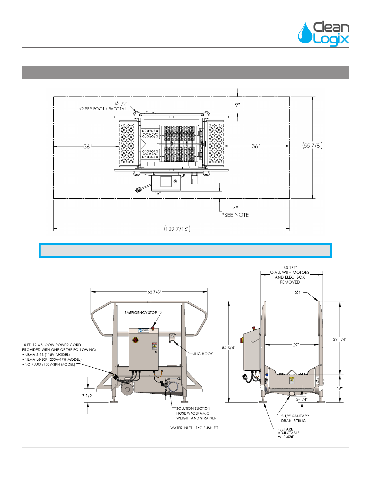
• Weight: 425 lb (192.78 kg)
• Dimensions: 62 7/8” x 45 3/8” x 54 3/4”
(1,597 x 1,152.5 x 1,390.65 mm)
• Max grate load: 350 lbs. (158.7 kg.)
• Water Consumpon: 0.75-1.5 GPM
(2.8 - 3.8 L/m)
• Minimum Chemical Diluon Rao: 1:230*
Specicaons
*NOTE: Unit tested at 70°F using water with
30-50 psi injector inlet pressure and capillary-
tube style injector metering p.
!
WARNING:
DO NOT use ammable liquids (i.e. alcohol
based soluons or similar) without diluon
unless equipped with a non-diluon ojet kit
(NDF model).
NOTE: Instrucons and specicaons are for
standard units only. See page 26 for units
equipped with Non-diluon kits (NDF).
BLX-900-GEN2 User Manual Page 4 of 29 Updated: 10/19/21
USER MANUAL: BLX-900S-GEN2
READ ALL INSTRUCTIONS BEFORE OPERATING EQUIPMENT
Installaon
NOTE: For xed installaons, area in front of electrical panel must have at least 36" of clearance.

BLX-900-GEN2 User Manual Page 5 of 29 Updated: 10/19/21
USER MANUAL: BLX-900S-GEN2
READ ALL INSTRUCTIONS BEFORE OPERATING EQUIPMENT
General
Installaon
OperaonAppendix Maintenance ConguraonTroubleshoong
Physical Set Up:
1. Set unit in desired locaon.
2. Aspects to consider when deciding on placement:
• Clearance for entering and exing
• Locaon of drain
• Emergency exit paths or egress in case of
emergency
• Head room for personnel while using the unit
• Access to control box
• Connecons for water and electricity
3. Use a level to make sure the unit is stable and
leveled at each end of the tub [Figure 5.1].
4. Connect unit to electrical supply.
Plumbing Connecons:
1. Connect water source to solenoid valve quick
ng inlet using 1/2" Polyethylene tubing or
similar [Figure 5.2].
2. If necessary, adjust the diluon rao by selecng
an appropriate metering p (included) and test.
• The smallest metering p is a yellow p with a
small tube aached [Figure 5.3].
• This tube can be trimmed to alter the diluon
rao.
• Full length capillary tube results in a diluon
rao of approximately 1:670 at 30-50 psi
water inlet pressure.
3. With the metering p installed, connect soluon
source to orange hose barb of the Venturi Injector
(located above water inlet) using 1/4" clear PVC
tubing (included) [Figure 5.2].
Installaon
NOTE: To move the unit use a pallet jack or
a hi-lo to li from the boom or using the
handrails. Pad the forks to protect the nish.
Fig. 5.2: Water and Venturi Injector (soluon) inlets
Capillary
Tube
Addional
Metering Tips
Fig. 5.3: Metering Tips and Capillary Tube
Fig. 5.1: Level and stabilize unit using level against end cap of tub

BLX-900-GEN2 User Manual Page 6 of 29 Updated: 10/19/21
USER MANUAL: BLX-900S-GEN2
READ ALL INSTRUCTIONS BEFORE OPERATING EQUIPMENT
Motor Speed Adjustment
The speed of the motor(s) is controlled by the Variable
Frequency Drive (VFD). To adjust the speed, turn the knob
on the front of the VFD while the unit is under power and
motor is running.
Default: 1750 RPM at 45 Hz
• Recommended speed: 45 Hz
• Minimum speed: 15 Hz
• Maxiumum Speed: 60 Hz
To adjust the speed:
1. Open the control box.
2. Acvate the sensor to turn on the motor.
3. As the motor is spinning, the unit will display the
operang speed in Hz.
4. Turn the knob counter clockwise to decrease the
speed, or clockwise to increase speed. [Figure 6.1]
Installaon (connued)
!
DANGER:
Do not open control box during wash down
or cleaning. Only authorized personnel should
open the control box.
Fig. 6.1: Delta MS300 (AD GS20) Variable Frequency Drive
Speed
Adjustment

BLX-900-GEN2 User Manual Page 7 of 29 Updated: 10/19/21
USER MANUAL: BLX-900S-GEN2
READ ALL INSTRUCTIONS BEFORE OPERATING EQUIPMENT
General
Installaon
OperaonAppendix Maintenance ConguraonTroubleshoong
Operaon
Fig. 7.2: Grate triggering Prox Switch (some components
hidden for clarity)
Start Up
1. Verify installaon has been completed:
• Brushes are secure
• Walkway grate is lowered
• Unit is plugged in and receiving power
• Water and soluon have been plumbed and
lines are open
2. Pull the E-STOP switches up and engage power,
the E-STOP will illuminate red when the unit is
receiving power [Figure 7.1].
Use
1. Step onto the walkway grate.
2. The walkway grate will depress, acvang a
proximity sensor which starts the brush rotaon
and soluon spray [Figure 7.2].
3. Walk through the unit, allowing the rotang
brushes to clean by moving the boot to make
contact with hard to reach areas.
4. One second aer the user steps o of the
walkway grate the brushes and sanizer will stop.
Shut Down
• Press the red E-STOP buon on the control box.
• Disconnect power and follow lockout-tagout
procedures as necessary.
!
CAUTION:
When operang: always ensure solid foong
and use both handrails for stability.
NOTE: Prior to placing footwear into the unit,
test that it is working properly by acvang
the sensor (put weight on the grate).
Fig. 7.1: E-STOP indicator light on control box

BLX-900-GEN2 User Manual Page 8 of 29 Updated: 10/19/21
USER MANUAL: BLX-900S-GEN2
READ ALL INSTRUCTIONS BEFORE OPERATING EQUIPMENT
Cleaning Procedures
Opening Grate
1. Shut down the unit (see pg. 5) and li the grate up
by its handle [Figure 8.1].
2. Swing the grate open completely
3. Latch into place against the pin aached to the
corner rail [Figure 8.2].
Fig. 8.1: Grate Liing, shown on BLX-1000S
!
CAUTION:
Failure to latch the grate properly could result
in grate falling closed unexpectedly.
INCOMPLETE COMPLETE
Fig. 8.2: Grate Latch Orientaon
!
CAUTION:
Use of high pressure (above 400 PSI) is not
recommended on sensive areas such as electrical
components, motors, or gearboxes.
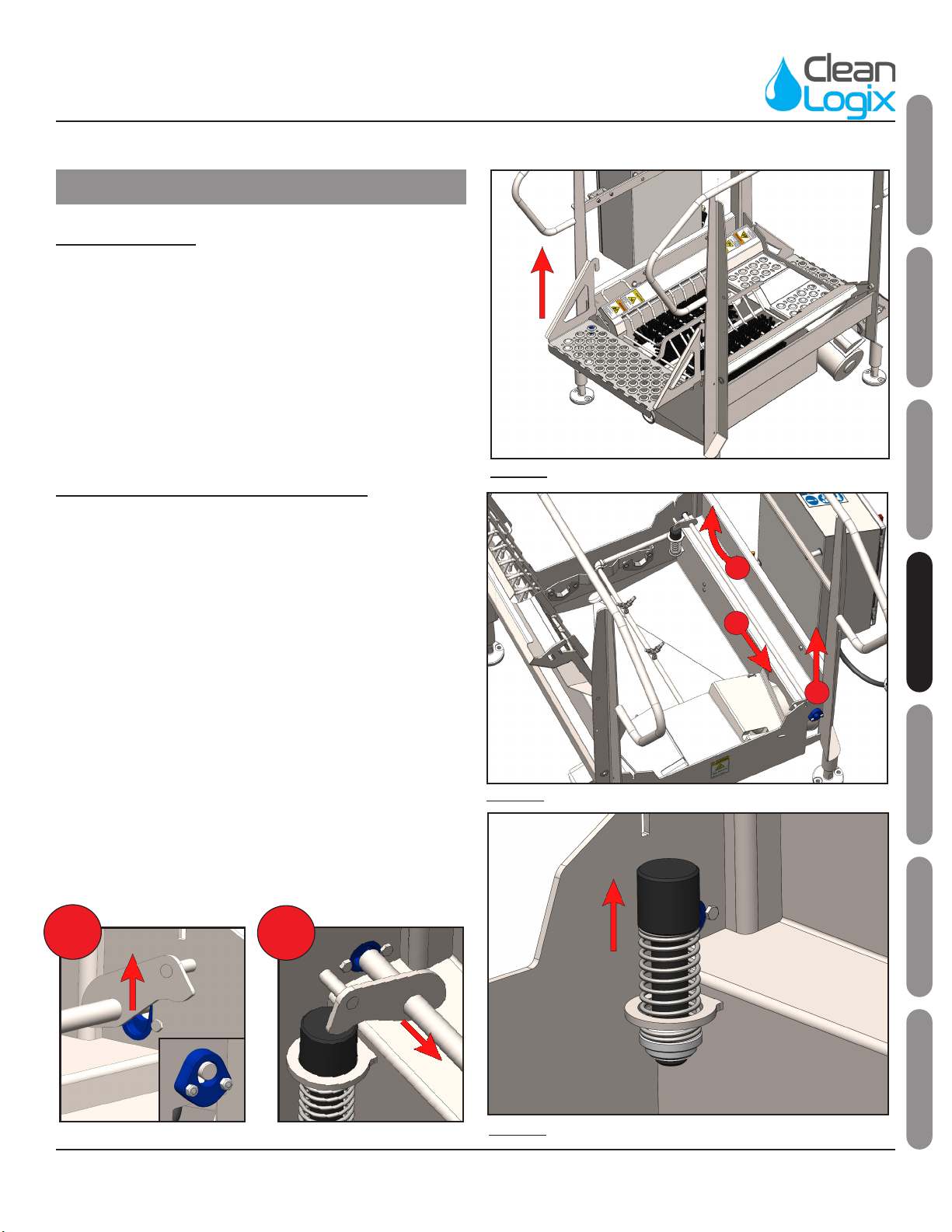
Removing & Replacing BrusheS
1. Shut down the unit and open the grate.
2. Li each brush out of the tub by grabbing the
open end and liing up [Figure 8.3 - Arrow 1].
3. With the open end lied, the brush can be
detached from its anchor [Figure 8.3 - Arrow 2].
4. Repeat this process to remove the other brush.
5. Brushes can be washed individually in a COP tank
or wash machine.
6. The tub can be washed by convenonal means.
NOTE: It is NOT recommended to use hot water
(over 120°F) to clean brushes.
Fig. 8.3: Brush removal process
2
1
BLX-900-GEN2 User Manual Page 9 of 29 Updated: 10/19/21
USER MANUAL: BLX-900S-GEN2
READ ALL INSTRUCTIONS BEFORE OPERATING EQUIPMENT
General
Installaon
OperaonAppendix Maintenance ConguraonTroubleshoong
Cleaning Procedures (connued)
Removing Steps
1. Shut down the unit.
2. Grab either side of the step by the handles.
3. Li up to remove from tub [Figure 10.1].
4. Steps can be washed individually in a COP tank or
wash machine.
5. Replace steps before enabling power and/or use.
Removing Grate Springs & Balancer
1. Open the Grate.
2. Li the end of the Spring Balancer into the upper
secon of its keyhole. [Figure 10.2 - Arrow 1]
3. Slide the Spring Balancer through the upper
secon of the keyhole to release its other end.
[Figure 10.2 - Arrow 2]
4. Li the free end up while sliding the Spring
Balancer out the keyhole to remove from the tub.
[Figure 10.2 - Arrow 3]
5. Slide each spring up to remove them from the tub
[Figure 10.3].
6. Springs and Balancer Weldment can be washed
individually in a COP tank or wash machine.
7. Once clean, re-install in reverse order.
Fig. 10.1: Step removal
Fig. 10.3: Spring removal procedure
Fig. 10.2: Balancer Weldment removal procedure
3
2
2
1
1
BLX-900-GEN2 User Manual Page 10 of 29 Updated: 10/19/21
USER MANUAL: BLX-900S-GEN2
READ ALL INSTRUCTIONS BEFORE OPERATING EQUIPMENT
Advanced Conguraon Opons
!
DANGER:
Do not open control box during wash down
or cleaning. Only authorized personnel should
open the control box.
Brush RPM Formula:
The formula for calculang Speed in RPM from Drive
Frequency in Hertz is:
[Motor Nameplate RPM] x [Drive Frequency (Hz)]
÷ [Motor Nameplate Frequency (Hz)] ÷ [Gear
Reducon]
Example:
• Motor Nameplate RPM = 1750
• Motor Nameplate Frequency (Hz) = 60
• Gear Reducon = 20
• Drive Frequency (Hz) = 48
1750 x 48 ÷ 60 ÷ 20 = 70 RPM
The formula for calculang Drive Frequency in Hertz
from Desired Speed in RPM is:
[Desired Speed RPM] x [Gear Reducon] x[Motor
Nameplate Frequency (Hz)] ÷ [Motor Nameplate
RPM]
Example:
• Desired Speed in RPM = 70
• Gear Reducon = 20
• Motor Nameplate Frequency (Hz) = 60
• Motor Nameplate RPM = 1750
70 x 20 x 60 ÷ 1750 = 48 Hz
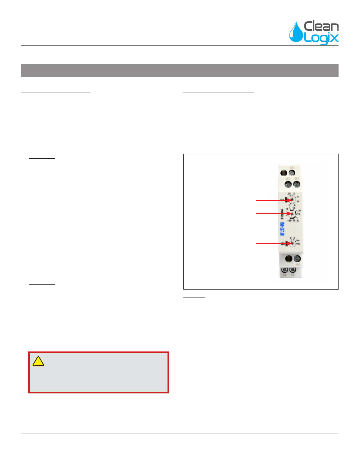
Timing Relay Sengs
Eaton TRL04
• Funcon: R (O Delay)
• Time Range: 1-10 seconds
• Seng: 1 second
FUNCTION
TIME RANGE
ADJUSTMENT RANGE
Fig. 12.2: Eaton TRL04 Seng Idencaon
BLX-900-GEN2 User Manual Page 11 of 29 Updated: 10/19/21
USER MANUAL: BLX-900S-GEN2
READ ALL INSTRUCTIONS BEFORE OPERATING EQUIPMENT
General
Installaon
OperaonAppendix Maintenance ConguraonTroubleshoong
Advanced Conguraon Opons (connued)
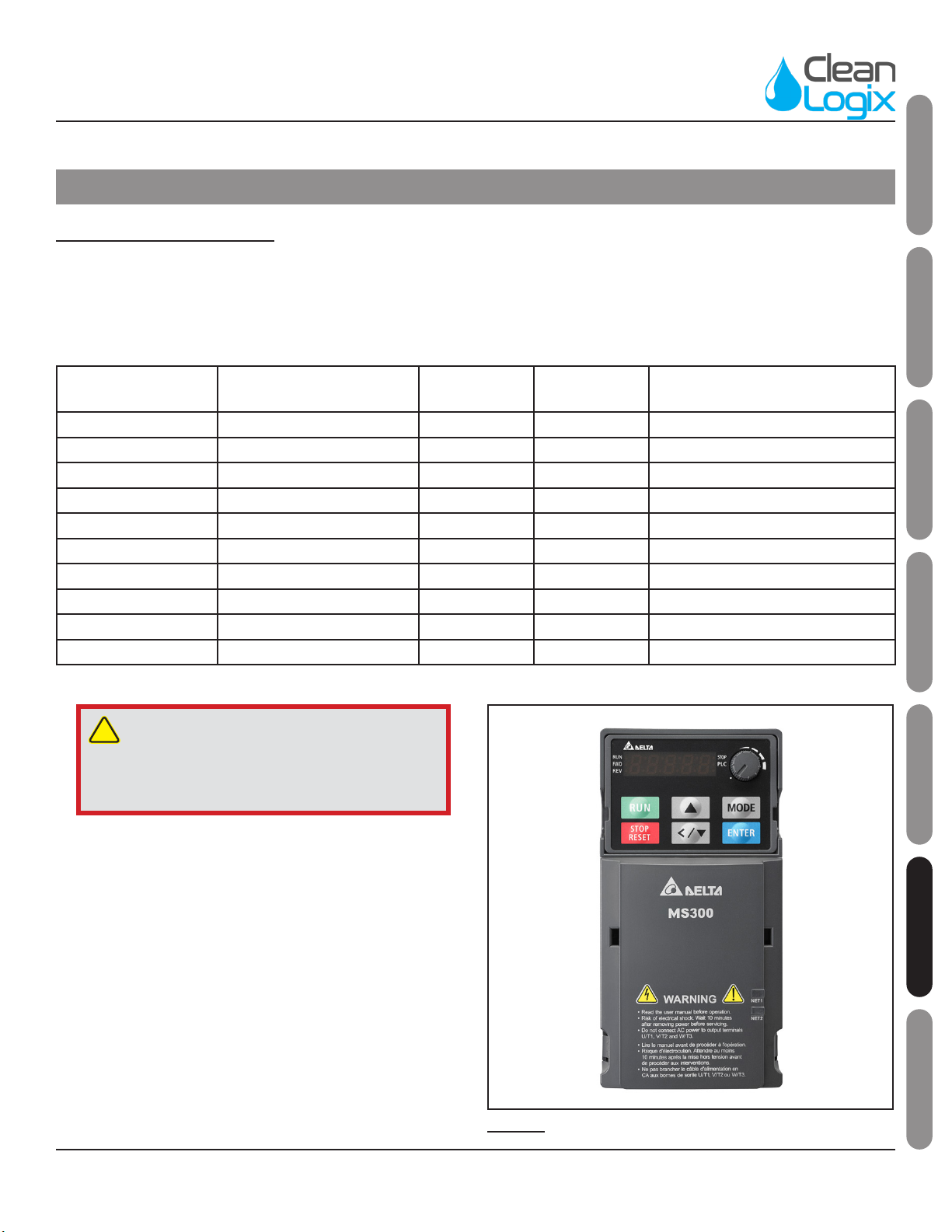
Drive Parameter Sengs
Delta MS300 (AD GS20) Variable Frequency Drive
Review drive specicaons for your system's specic
power requirements (115V, 230V, or 480V).
PARAMETER
NUMBER DESCRIPTION 115V - 230V 480V UNITS/DESC
P00.20 Source of Frequency 7 7 Digital Keypad Dial
P00.21 Source of Oper 1 1 External Terminals
P01.12 1st ACC Time 1 1 Seconds
P01.13 1st DEC Time 2 2 Seconds
P02.13 Mul Funct Relay 22 7 Overcurrent Stall Protecon
P06.03 OCA Level 90 47 Percent
P06.04 OCN Level 90 47 Percent
P06.06 Over TQC1 Method 4 4 Stop Aer Overtorque
P06.07 Over TQC1 Level 90 47 Percent
P06.08 Over TQC1 Time 0.3 0.3 Seconds
!
DANGER:
Do not open control box during wash down
or cleaning. Only authorized personnel should
open the control box.
Fig. 12.1: Delta MS300 (AD GS20) Variable Frequency Drive

BLX-900-GEN2 User Manual Page 12 of 29 Updated: 10/19/21
USER MANUAL: BLX-900S-GEN2
READ ALL INSTRUCTIONS BEFORE OPERATING EQUIPMENT
The following maintenance procedures are
recommended for normal use. Units which see a
high amount of daily use should be inspected more
frequently as necessary.
Weekly:
• Check unit for proper sensor funcon and brush
rotaon.
• Ensure spring loaded grate (if applicable) is
funconing properly.
• Inspect brushes for damage or wear. Check for
missing or deformed bristles.
• Inspect electrical cords and plumbing for
damage.
• Inspect and test funcon of emergency stop
switches.
Monthly:
• Check all fasteners to ensure they are ght.
• Ensure warning labels and decals are present
and in good condion.
• Inspect motors, gearboxes, and reducers for
signs of oil leakage.
• Inspect electrical enclosure for signs of water
intrusion.
• Inspect sensors for damage.
• Inspect moving parts for damage or wear.
Quarterly:
• Inspect structure for cracked welds or bent
components.
Gear Reducer:
• The gear reducer is supplied lled to capacity
with Mobil Cibus SHC 634 NSF H1 Food Grade
or equal synthec oil.
• The synthec lubricaon provided is
good for ambient temperatures -10°F -
105°F and is compable with standard
compounded oil.
• Oil should be changed every 2 years (or 6,000
operang hrs.)
• Designed with a bladder type vent system:
• Consists of an internal bladder that
seals the oil chamber from the outside
environment at all mes - as pressure
builds, the bladder contracts keeping the
internal pressure to a minimum.
• Advantage: The internal oil chamber is
completely sealed, ensuring oil is not
released causing contaminaon in the
applicaon.
Motor:
• Inspect at regular intervals.
• Keep clean and venlang openings (on TEFC
motors) clear of any obstrucons.
• Verify the mounng bolts and couplings
to ensure that they are ght and properly
adjusted.
• Motor bearings are sealed and not
re-greasable.
• Bearings should be replaced approximately
every 5 years for 8 hr./day service.
Preventave Maintenance
NOTE: Control box is equipped with a Lock-
Out/Tag-Out switch for restricted power
access when performing maintenance
procedures.

BLX-900-GEN2 User Manual Page 13 of 29 Updated: 10/19/21
USER MANUAL: BLX-900S-GEN2
READ ALL INSTRUCTIONS BEFORE OPERATING EQUIPMENT
General
Installaon
OperaonAppendix Maintenance ConguraonTroubleshoong
Unit will not operate:
• Follow the startup procedure (pg. 5)
• Verify the control box is closed and the power-
disconnect switch is in the ON posion.
• Verify that there is power going to the unit.
• Verify the circuit breakers in the building
have not been tripped.
Unit will not spray:
• Verify water pressure at the inlet to the water/
soluon solenoid (35 psi min.)
• Inspect spray nozzles for clogging.
• Verify that the orange LED light on the solenoid
valve connector illuminates when the brushes
are rotang.
Green START buon is illuminated, but one
or more brushes will not rotate when unit is
acvated:
• Power cycle the unit by turning the disconnect
switch to OFF and then back to ON. Follow the
start up procedure on Page 6.
OT1 Fault Code "Over-Torque 1" on Variable
Frequency Drive:
The fault occurs when the torque load on any brush
exceeds the value set in parameter P06.03 [OCA
Level]. The soluon will stop spraying when a fault
occurs.
• Switch Disconnect to "OFF" or unplug the unit.
• Wait 20-30 seconds before re-applying power
to cycle power and clear the fault.
Troubleshoong
Unit is leaking onto oor:
• Check to make sure all joints are sealed.
• Verify water and soluon inlets are aached and
rmly in place.
Leaner Diluon Raos Required:
• Verify metering p is installed in the injector
chemical inlet hose barb
• Use the yellow “Capillary Tube” style metering p
(see pg. 4 for further informaon)
• If the desired diluon rao sll cannot be
achieved pre-diluon of the chemical may be
necessary.
Venturi will not draw Chemical Soluon:
• Verify water supply is sustaining 30 psi at the
injector inlet while unit is running
• Elevate the chemical jug above the injector (a jug
hook is provided for this purpose)
• Verify spray nozzles are not clogged. The nozzles
supplied with the equipment are rated at 0.2GPM
@ 10psi (0.28GPM @ 20 psi)
• Ensure the sucon lter is not clogged, kinked or
obstructed in any way that would restrict ow.

BLX-900-GEN2 User Manual Page 14 of 29 Updated: 10/19/21
USER MANUAL: BLX-900S-GEN2
READ ALL INSTRUCTIONS BEFORE OPERATING EQUIPMENT
Appendix A - Parts Callout (BLX-900-GEN2)
M2193 (115V)
M2194 (230V)
M2195 (480V)

BLX-900-GEN2 User Manual Page 15 of 29 Updated: 10/19/21
USER MANUAL: BLX-900S-GEN2
READ ALL INSTRUCTIONS BEFORE OPERATING EQUIPMENT
General
Installaon
OperaonAppendix Maintenance ConguraonTroubleshoong
Appendix A - Parts Callout (BLX-900-GEN2)
Part No. Descripon
F1000 STANDOFF 1/4-20 x 1/2 x 1/2 SS
F1040 BOLT HHC 5/16-18 x 1-1/4 SS
F1047 NUT NYLOCK 1/4-20 SS
F1052 NUT NYLOCK 5/16-18 SS
F1056 WASHER 1/4 SS TYPE A
F1066 NUT NYLOCK 10-32 SS
F1078 WASHER .5 X .88 X .06 UHMW
F1083 BOLT HHC 1/4-20 x 1-1/4 SS
F1085 WASHER FENDER 5/16-18 SS
F1088 BOLT HHC 1/4-20 X 1-3/4 SS
F1126 BOLT HHC 10-32 X 1 SS
F1130 BOLT HHC 5/16-18 X 5/8' SS
F1135 STANDOFF 1/4 X 1/2 X 3/16 SS
F1136 STANDOFF 1/4 X 1/2 X 1 SS
F1139 BOLT SHUTTER 1/4-20 X 1 SS
F1166 BOLT HHC 5/16-18 X 2-1/4' SS
M1134 SOLENOID BRACKET
M1183 DRIVE SHAFT MOTOR-BRUSH WELDMENT
M1237 GRATE LATCH
M1420 BRUSH SUPPORT WELDMENT
M1534 SPACER .313 X .5 X 1.5
M1720 BRUSH BLX HORIZONTAL SOLE
M1746 BLX GEN2 JUG HOOK
M1758 BLX GEN2 GRATE STEPPED HINGE PIN
M1795 BLX FORMED STEP 24 INCH
M1850 BLX-1000 GEN2 SPRAY NOZZLE RISER
WELDMENT
M1851 BLX-1000 GEN2 PIPE NIPPLE
M1852 BLX-1000 GEN2 MOTOR COVER
M1892 BLX-800 GEN2 SPRING BALANCER WELDMENT
V3
M1894 BLX C-CHANNEL GRATE LIFT PIN GLIDE
M1896 BLX GEN2 GRATE SPRING ASSEMBLY
M1904 BLX GEN2 SPRING BALANCER BEARING ROUND
M1905 BLX GEN2 SPRING BALANCER BEARING
SLOTTED
M1981 BLX-900 GEN2 TUB WELDMENT
M1982 BLX-900 GEN2 SPRAY MANIFOLD WELDMENT
Part No. Descripon
M1986 BLX-900 GEN2 GRATE V3 WLDMNT
P1005 STERLING SS MOTOR 1/2HP, 1800 RPM,
230/460/3/60, TENV, 56C FOOTLESS
P1006 STERLING GEAR REDUCER 20:1, 56C
P1046 VALVE, SOLENOID, 3/8" SS 24VDC DIN COIL, DEMA
463PS.4D
P1121 Induce Proxy 18mm PP 8mm RN 4-Wire DC
N.E./M.C. M12 IQ/D Shielded
P1147 CORD GRIP 1/2 NPT X .170-.450 BLK HEYCO M3231
P1148 CORD GRIP NUT 1/2' NPT BLACK - HEYCO 8463
P1187 SOLENOID CABLE 18MM DIN 24V LED 3M SC18-
LS24-3
P1242 TERMINAL, 1/4" RING, 14-16 AWG INS
P1252 PIPE PLUG 1/4" NPT SOCKET HD SS
P1331 1/2" OD POLYETHYLENE TUBING - NATURAL
P1400 CABLE, M12, 4 POLE, 5m (16.48 ), RT-ANG
FEMALE/AXIAL MALE
P1418 QUICK FIT ADAPTER 3/8 NPT X 1/2 TUBE PP
P1511 QUICK FIT STEM ELBOW 1/2' X 1/2'
P1599 METERING TIP, CAPILLARY TUBE
P1769 METERING TIPS, ULTRA LEAN 100-15KU
P1828 WIRE, VFD-MOTOR, 14 AWG, 4-CONDUCTOR,
SHIELDED, XLPE/PVC
P1830 PIPE ELBOW 3/8" x 90 304SS
P1903 VENTURI INJECTOR DEMA ROCKET, ORANGE,
.070", 1.3GPM@100PSI, SINGLE BARB
P1934 GREASE, ELECTRIC INSULATING .17OZ ONE TIME
USE PACK
P1944
NOZZLE, FAN SPRAY, 110 DEGREE, 1/8 MNPT,
304SS, FLOODJET TYPE K, 0.2 GPM @ 10 PSI
(1/8KSS-2)
P1945 VENTURI INJECTOR 1/4" SUCTION LINE AND
STRAINER
P1946 VENTURI INJECTOR SUCTION WEIGHT CERAMIC
FOR 1/4" TUBE

BLX-900-GEN2 User Manual Page 16 of 29 Updated: 10/19/21
USER MANUAL: BLX-900S-GEN2
READ ALL INSTRUCTIONS BEFORE OPERATING EQUIPMENT
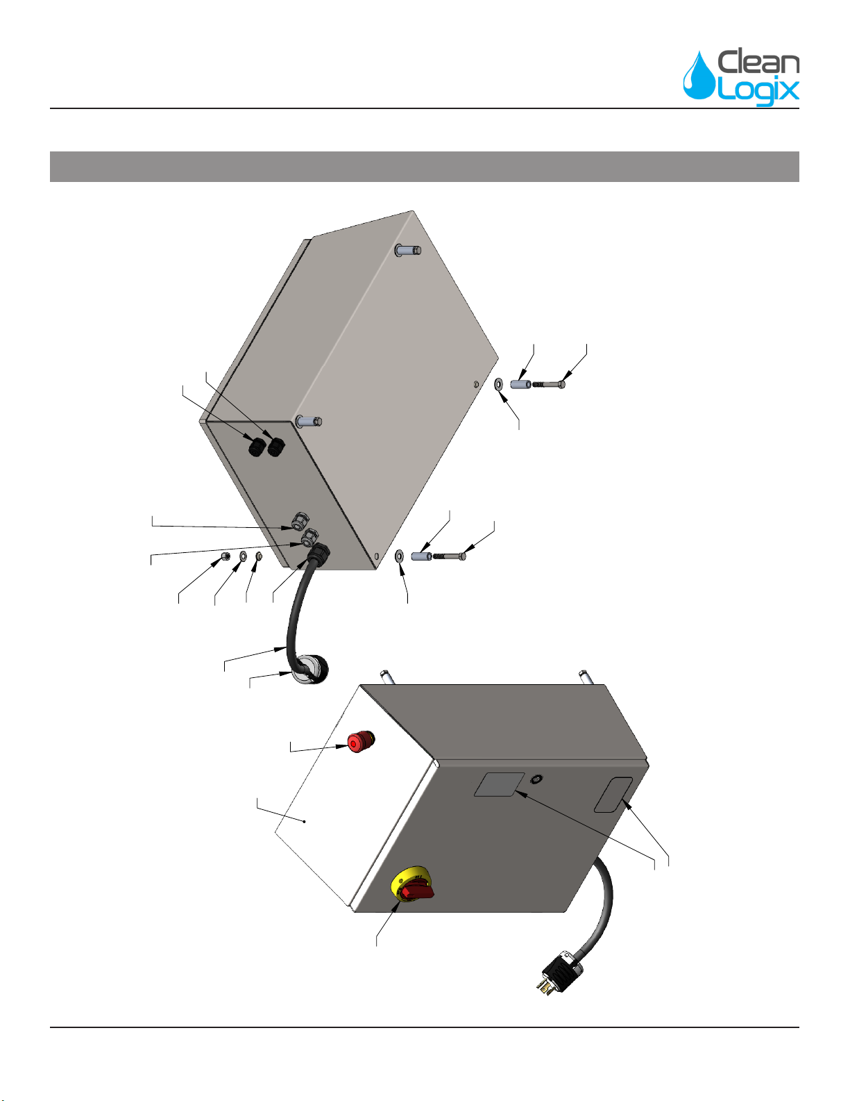
Appendix A - Parts Callout (M2193 : 115V, 1PH)
P1449
P1228
P1246
M1888
F1177
F1177
F1140
F1140
NONE
NONE
F1059
P1361
P1184
P1515
P1184
P1515
M1819
M1819
P1585
M2193 - 115V, 1PH
FOR ELECTRICAL SCHEMATIC, REFER TO
DRAWING NUMBER
ES1043
BLX-900-GEN2 User Manual Page 17 of 29 Updated: 10/19/21
USER MANUAL: BLX-900S-GEN2
READ ALL INSTRUCTIONS BEFORE OPERATING EQUIPMENT
General
Installaon
OperaonAppendix Maintenance ConguraonTroubleshoong
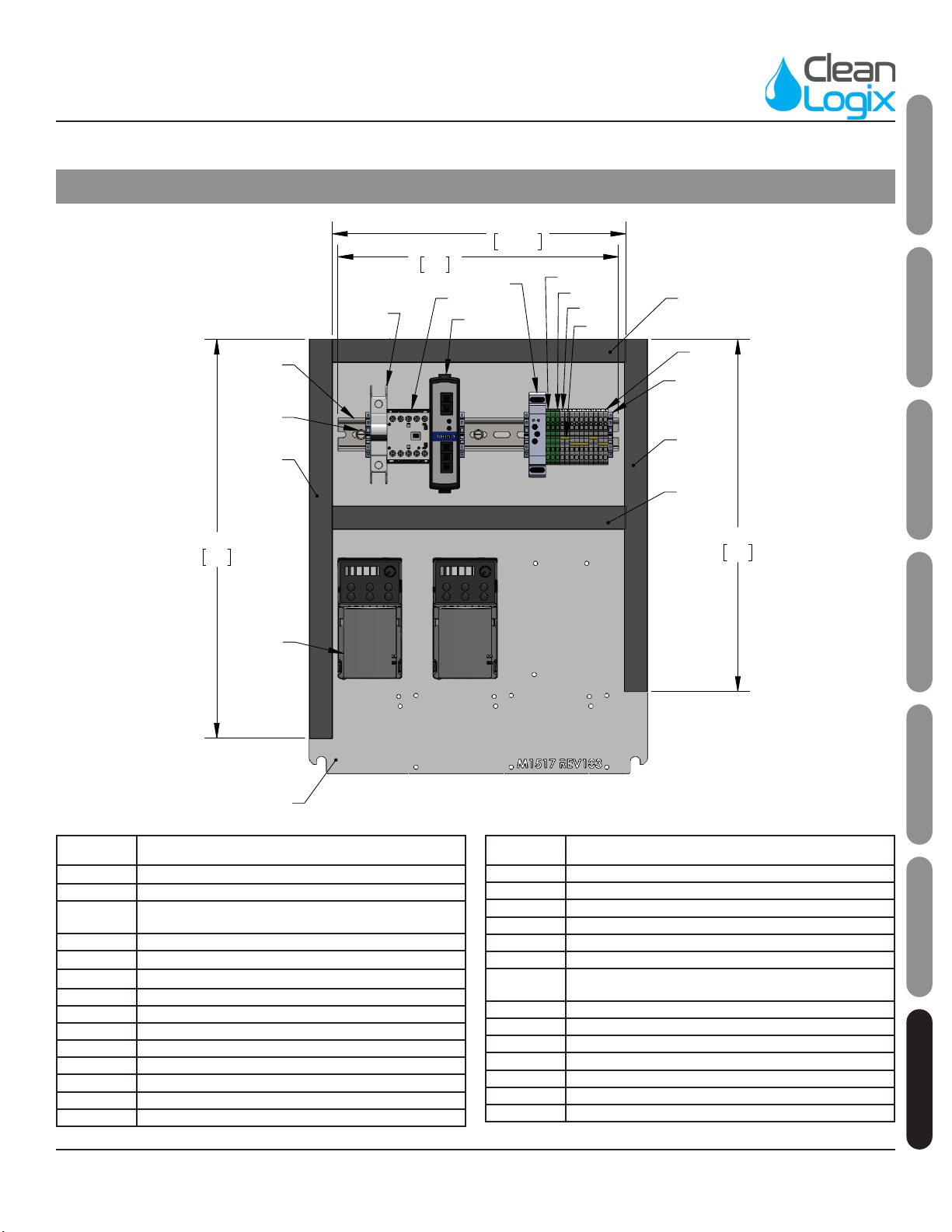
Appendix A - Parts Callout (M2193 : 115V, 1PH)
14 3/4"
375
12 1/4"
312.50
16 3/4"
425
11 3/4"
299
P1172
P1172
P1172
P1172
P1169
P1122
P1939
P1111
F1172
P1874
P1874
P1873
P1880
P1881
M1517
P2429
P2444
P2052
FOR ELECTRICAL SCHEMATIC, REFER TO
DRAWING NUMBER
ES1043
M2193 - 115V, 1PH
Part No. Descripon
F1059 NUT NYLOCK 3/8-16 SS
F1140 WASHER SEALING 3/8 X 1 SS
F1172 SCREW THEAD FORMING 10-32 X 1/2 HEX WASHER
HEAD ZINC
F1177 BOLT HHC 3/8-16 X 2-1/2 SS
M1819 SPACER 3/8" X 1-1/2" SS
P1111 END STOP TERMINAL BLOCK
P1122 POWER SUPPLY 24VDC 60W
P1148 CORD GRIP NUT 1/2 NPS NYL
P1169 DIN RAIL 35mm X 300mm LONG
P1172 WIRE DUCT 25X60 X 312mm LONG
P1172 WIRE DUCT 25X60 X 375mm LONG
P1172 WIRE DUCT 25X60 X 425mm LONG
P1184 CORD GRIP 1/2 NPT X .095-.260 BLK
P1200 PLUG NEMA 5-15P
Part No. Descripon
P1228 ENCLOSURE HOFFMAN CONCEPT CSD20168SSST
P1246 LABEL DANGER ELECTRICAL
P1361 CORD GRIP 3/4 NPT X .435-.705 BLK
P1363 CORD GRIP NUT 3/4 NPT NYLON
P1449 E-STOP PUSH PULL ILLUMINATED 22mm 2NC
P1515 CORD GRIP PG16 X .260-.545 GREY W/NUT
P1585 WIRE SJOOW 12AWG 4 CONDUCTOR BLACK (0.650 OD)
600V 02726.41T.01
P1873 TERMINAL BLOCK SPRING CLAMP 5.1mm GRAY
P1874 TERMINAL BLOCK SPRING CLAMP 5.1mm GROUND
P1880 TERMINAL JUMPER 5.1mm
P1939 RELAY, TIMER, MULTIFUNCTION 24VDC
P2052 CIRCUIT BREAKER 20A, SINGLE POLE, D-CURVE
P2429 VARIABLE FREQUENCY DRIVE MS300 0.5HP 115-1PH
P2444 IEC CONTACTOR 3P 16A 24VDC 1 NO AUX CONTACTOR
BLX-900-GEN2 User Manual Page 18 of 29 Updated: 10/19/21
USER MANUAL: BLX-900S-GEN2
READ ALL INSTRUCTIONS BEFORE OPERATING EQUIPMENT
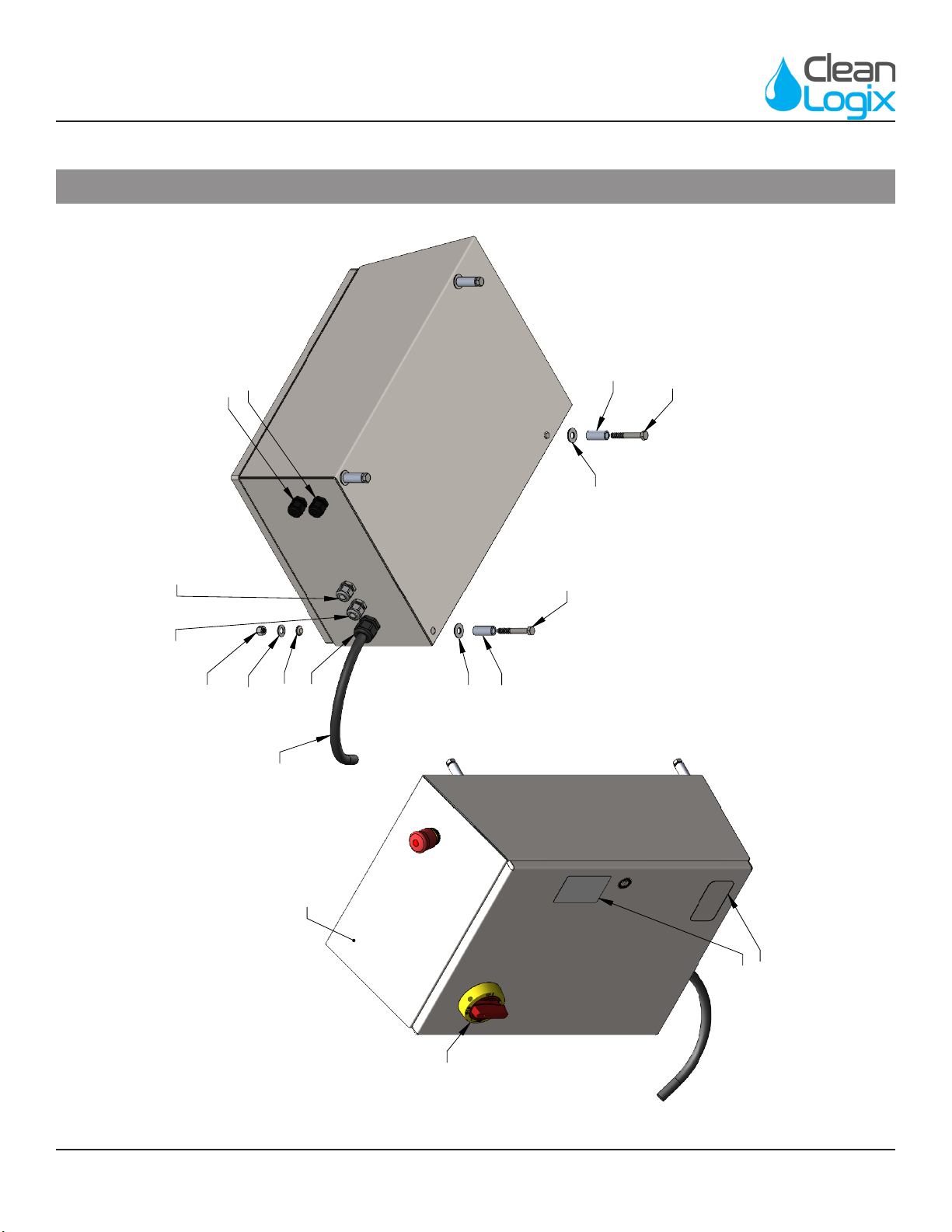
Appendix A - Parts Callout (M2194 : 230V, 1PH)
P1820
P1449
P1228
P1246
P1819
M1888
F1177
F1177
F1140
F1140
NONE
NONE
F1059
P1361
P1184
P1515
P1184
P1515
M1819
M1819
P1585
P1533
M2194 - 230V, 1PH
FOR ELECTRICAL SCHEMATIC, REFER TO
DRAWING NUMBER
ES1045
BLX-900-GEN2 User Manual Page 19 of 29 Updated: 10/19/21
USER MANUAL: BLX-900S-GEN2
READ ALL INSTRUCTIONS BEFORE OPERATING EQUIPMENT
General
Installaon
OperaonAppendix Maintenance ConguraonTroubleshoong
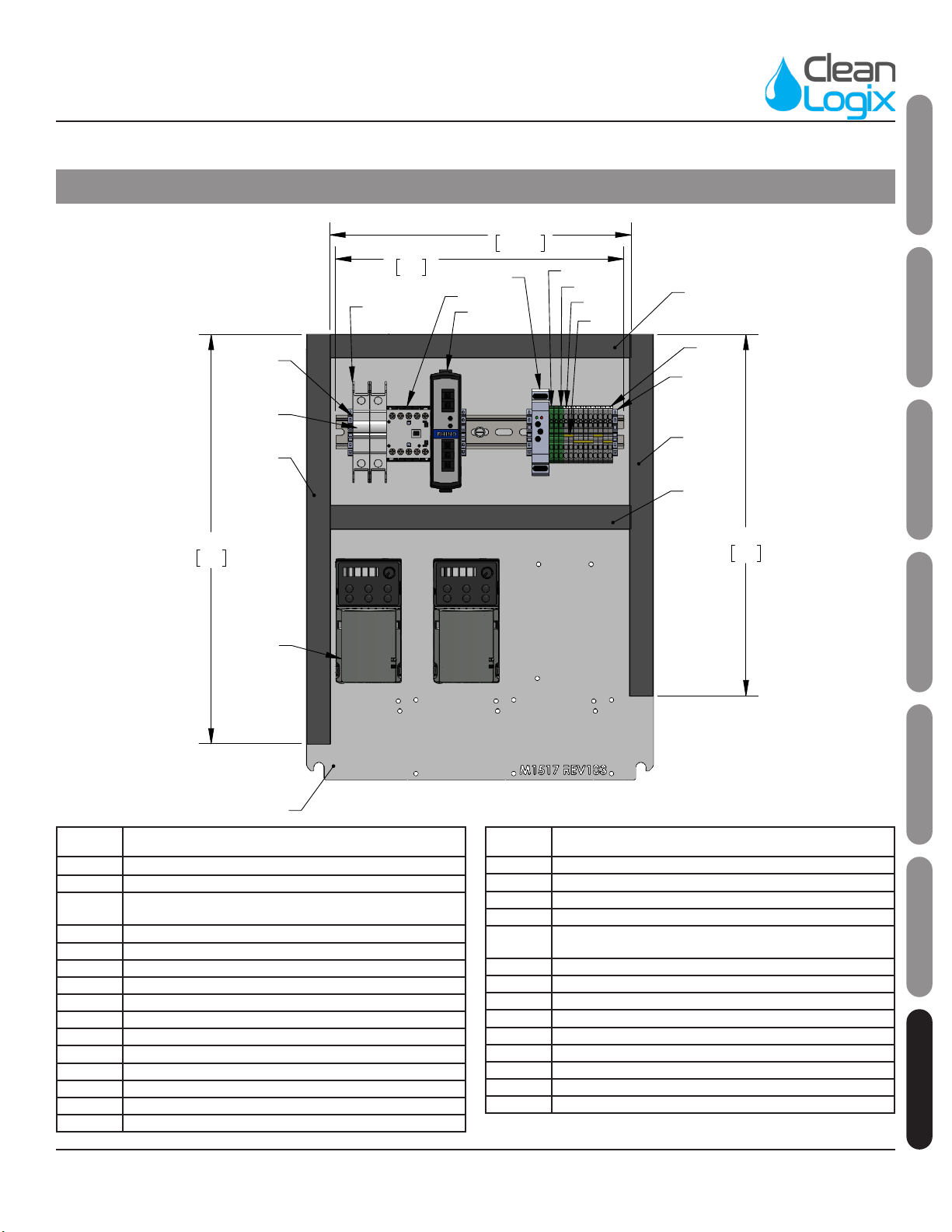
Appendix A - Parts Callout (M2194 : 230V, 1PH)
14 3/4"
375
12 1/4"
312.50
16 3/4"
425
11 3/4"
299
P1172
P1172
P1172
P1172
P1169
P1325 P1122
P1939
P1111
F1172
P1874
P1874
P1873
P1880
P1881
M1517
P2430
P2444
FOR ELECTRICAL SCHEMATIC, REFER TO
DRAWING NUMBER
ES1045
M2194 - 230V, 1PH
Part No. Descripon
F1059 NUT NYLOCK 3/8-16 SS
F1140 WASHER SEALING 3/8 X 1 SS
F1172 SCREW THEAD FORMING 10-32 X 1/2 HEX WASHER HEAD
ZINC
F1177 BOLT HHC 3/8-16 X 2-1/2 SS
M1819 SPACER 3/8" X 1-1/2" SS
P1111 END STOP TERMINAL BLOCK
P1122 POWER SUPPLY 24VDC 60W
P1148 CORD GRIP NUT 1/2 NPS NYL
P1169 DIN RAIL 35mm X 300mm LONG
P1172 WIRE DUCT 25X60
P1184 CORD GRIP 1/2 NPT X .095-.260 BLK
P1228 ENCLOSURE HOFFMAN CONCEPT CSD20168SSST
P1246 LABEL DANGER ELECTRICAL
P1325 CIRCUIT BREAKER 13A DOUBLE POLE
P1361 CORD GRIP 3/4 NPT X .435-.705 BLK
Part No. Descripon
P1363 CORD GRIP NUT 3/4 NPT NYLON
P1449 E-STOP PUSH PULL ILLUMINATED 22mm 2NC
P1515 CORD GRIP PG16 X .260-.545 GREY W/NUT
P1533 250V 30A L6-30 MALE PLUG
P1585 WIRE SJOOW 12AWG 4 CONDUCTOR BLACK (0.650 OD)
600V 02726.41T.01
P1758 LABEL - UL508 PANEL
P1819 DISCONNECT SWITCH 25A 3-POLE
P1820 DISCONNECT HANDLE KIT RED/YELLOW FOR P1819
P1873 TERMINAL BLOCK SPRING CLAMP 5.1mm GRAY
P1874 TERMINAL BLOCK SPRING CLAMP 5.1mm GROUND
P1880 TERMINAL JUMPER 5.1mm - 10 POSITION CUT TO 2
P1939 RELAY, TIMER, MULTIFUNCTION 24VDC (REPLACES P1115)
P2430 VARIABLE FREQUENCY DRIVE MS300 0.5HP 230-1PH
P2444 IEC CONTACTOR 3P 16A 24VDC 1 NO AUX CONTACTOR
BLX-900-GEN2 User Manual Page 20 of 29 Updated: 10/19/21
USER MANUAL: BLX-900S-GEN2
READ ALL INSTRUCTIONS BEFORE OPERATING EQUIPMENT
Appendix A - Parts Callout (M2195 : 480V, 3PH)
P1246
P1820
P1228
P1819
M1888
F1177
F1177
F1140
F1140
NONE
NONE
F1059
P1361
P1184
P1515
P1184
P1515
M1819
M1819
P1585
FOR ELECTRICAL SCHEMATIC, REFER TO
DRAWING NUMBER
ES1047
M12195 - 480V, 3PH
Table of contents
Other Clean Logix Cleaning Equipment manuals

Clean Logix
Clean Logix ALX-OMNI-LITE User manual

Clean Logix
Clean Logix BLX-1000-GEN2 User manual

Clean Logix
Clean Logix ALX-PRO User manual

Clean Logix
Clean Logix BLX-600-GEN2 User manual

Clean Logix
Clean Logix BLX-800-GEN2 User manual

Clean Logix
Clean Logix BLX-400 User manual

Clean Logix
Clean Logix BLX-700-GEN2 User manual

Clean Logix
Clean Logix EPX-TM User manual
Popular Cleaning Equipment manuals by other brands


Bissell
Bissell SPOTCLEAN AUTO 4720K user guide

Ultrawave
Ultrawave Q Series Operator's instruction manual

Nilfisk-Advance
Nilfisk-Advance Liberty SC50 Instructions for use

Kwunphi
Kwunphi Kwun-E22H manual

Alfalaval
Alfalaval Gunclean Toftejorg TZ-75 instruction manual

SkyVac
SkyVac Internal 37 Assembly & user's guide