BLX-600-GEN2 User Manual Page 15 of 19 Updated: 09/02/22
USER MANUAL: BLX-600-GEN2
READ ALL INSTRUCTIONS BEFORE OPERATING EQUIPMENT
General
Installaon
OperaonAppendix Maintenance ConguraonTroubleshoong
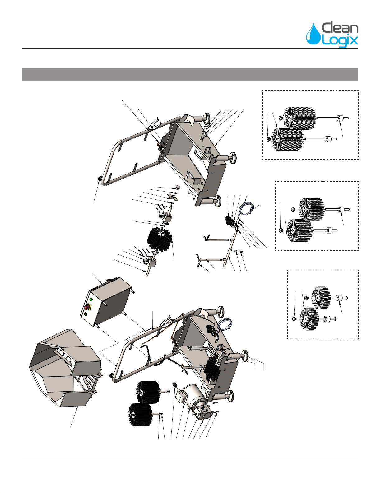
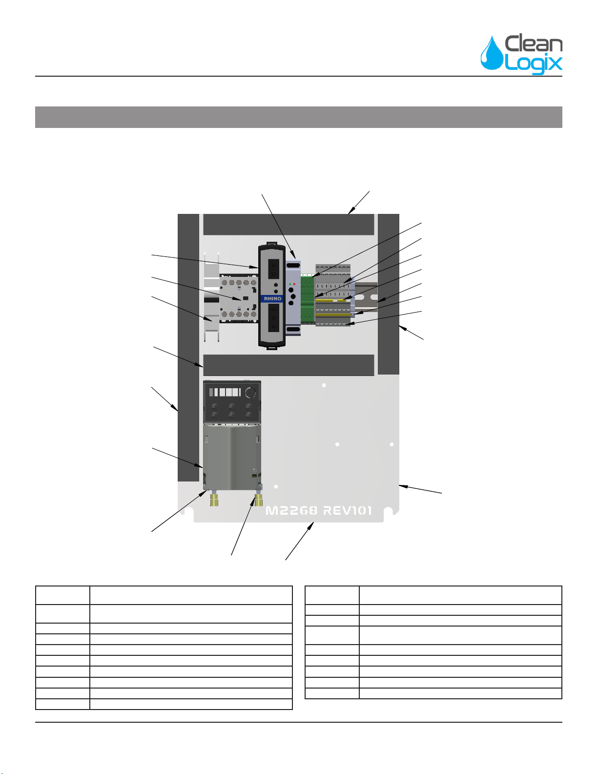
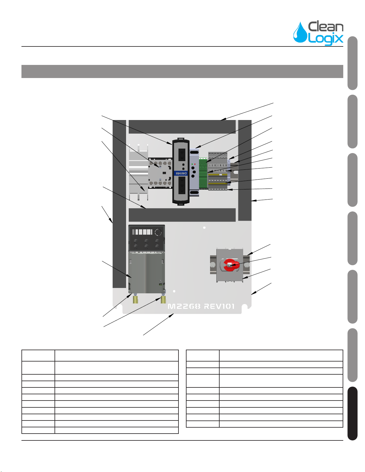
Appendix A - Parts Callout : BLX-600
Part No. Descripon
F1000 STANDOFF 1/4 x 1/2 x 1/2 SS
F1001 Washer 3/4" X 1-1/4" X 1/16" PTFE
F1002 BEARING FLANGED 1/2' X 5/8' X 1/4' PTFE
F1046 NUT HEX FLANGED 1/4-20 SS
F1047 NUT NYLOCK 1/4-20 SS
F1056 WASHER 1/4 SS TYPE A
F1078 WASHER .5 X .88 X .06 UHMW
F1088 BOLT HHC 1/4-20 X 1-3/4 SS
F1126 BOLT HHC 10-32 X 1 SS
F1129 BOLT HHC 5/16-18 X 1-1/2 SS
F1136 STANDOFF 1/4 X 1/2 X 1 SS
M1021 BRUSH SHAFT WELDMENT BLX-600
M1025 BRUSH, CYLINDER, 8" DIA. X 3" LONG, BLACK
PP FILAMENT
M1026 HORIZONTAL BRUSH BLX-600/800/1000 8"
DIAMETER, 6" WIDE
M1027 DRIVE SHAFT 1 WELDMENT BLX-600
M1030 Brush Coupler BLX-600
M1057 BRUSH KNOB WELDMENT FEMALE
M1134 SOLENOID BRACKET
M1570 SPACER 5/16 X 1/2 X 1 SS
M1618 BRUSH VERTICAL CYL 8 X 6
M1623 BRUSH SHAFT WLDMNT V-6
M1928 BRUSH, CYLINDER, 8" DIA. X 9" LONG, BLACK
PP FILAMENT
M1932 BRUSH SHAFT WLDMNT V9
M2212 BLX-600 GEN2 V9 SPRAY BAR
M2213 BLX-600 GEN2 SPRAY BAR WELDMENT SOLE
V3
M2214 BLX-600 GEN2 TUB WELDMENT
M2311 BLX-600V GEN2 GRATE WELDMENT
M2363 BLX-V SHAFT LATCH V2
M2366 BLX-600 GEN2 SPRING BAR WELDMENT
M2382 BLX-400-600 GEN2 ELECTRICAL ASSEMBLY -
230V-1PH
M2386 BLX-400-600 GEN2 ELECTRICAL ASSEMBLY -
115V-1PH
P1005 STERLING SS MOTOR 1/2HP, 1800 RPM,
230/460/3/60, TENV, 56C FOOTLESS
Part No. Descripon
P1006 STERLING GEAR REDUCER 20:1
P1041 Photo Eye, Allen-Bradley 42EF, 24VDC
P1046 VALVE, SOLENOID, 3/8" SS 24VDC DIN COIL,
DEMA 463PS.4D
P1121
SENSOR, INDUCTIVE PROXIMITY, 18mm PP
8mm RN 4-Wire DC N.E./M.C. M12 IQ/D
Shielded
P1186 KNOB 1-1/2 x 5/16-18 THREADED HOLE SS
60205K68
P1187 SOLENOID CABLE 18MM DIN 24V LED 3M
SC18-LS24-3
P1219 QUICK FIT ADAPTER 3/8" NPT x 3/8" TUBE
P1244 LABEL PINCH POINT HAZARD
P1245 LABEL MOVING PARTS
P1247 LABEL BLX NOTICE
P1248 LABEL SLIP HAZARD
P1400 CABLE, M12, 4 POLE, 5m (16.48 ), RT-ANG
FEMALE/AXIAL MALE
P1515 CORD GRIP PG16 X .260-.545 GREY W/NUT
P1599 METERING TIP, CAPILLARY TUBE
P1677 SPLICE TERMINAL 10-16 AWG NATURAL
P1753 Branham SSIAS1101 : 1LHA.625B.625 Right
Angle Gear Box
P1769 METERING TIPS, ULTRA LEAN 100-15KU
P1830 PIPE ELBOW 3/8" x 90 304SS
P1903 VENTURI INJECTOR DEMA ROCKET, ORANGE,
.070", 1.3GPM@100PSI, SINGLE BARB
P1944
NOZZLE, FAN SPRAY, 110 DEGREE, 1/8 MNPT,
304SS, FLOODJET TYPE K, 0.2 GPM @ 10 PSI
(1/8KSS-2)
P1945 VENTURI INJECTOR 1/4" SUCTION LINE AND
STRAINER
P1946 VENTURI INJECTOR SUCTION WEIGHT
CERAMIC FOR 1/4" TUBE
P2199 CHECK VALVE 1/8"F X 1/8"M 1# SS
P2542 PIPE NIPPLE 3/8" X 3.5" L 304SS