Clean Logix BLX-1000-GEN2 User manual

USER
MANUAL
English (Original Instrucons)
Updated: 02/11/21
MODEL:
BLX-1000-GEN2
Full Walkthrough Boot Scrubber
BLX-1000S
Sole Only
BLX-1000V
Vercal
BLX-1000R
Regular

BLX-1000-GEN2 User Manual Page 2 of 29 Updated: 02/11/21
USER MANUAL: BLX-1000-GEN2
READ ALL INSTRUCTIONS BEFORE OPERATING EQUIPMENT
!
WARNING:
1. All personnel using this unit must be familiar with
the informaon contained in this manual. Follow all
installaon and maintenance instrucons.
2. Always wear appropriate footwear. Secure or remove
loose items on footwear.
3. Ensure solid foong and use both hands when operang
the unit.
4. Avoid contact of chemicals with skin and eyes. If contact
occurs, see MSDS sheet for further rst aid measures.
5. Follow safety instrucons of chemical manufacturer
(MSDS).
6. Always follow plant and OSHA guidelines about the use
of equipment.
7. Disconnect power before servicing equipment.
8. Always follow safety precauons and obey warning
labels. Failure to do so could result in injury or death.
Table of Contents
System Requirements
Specicaons
Installaon
Physical Set-Up
Plumbing Connecons
Motor Speed Adjustment
Operaon
Start Up
Use
Shut Down
Cleaning
Opening Grate
03
04
06
07
08
09
09
09
10
Removing Brushes
Removing Steps & Spring Balancer
Advanced Conguraon
Motor Current Sensor
Brush RPM Adjustment
Drive Parameters
Timing Relay
Maintenance
Troubleshoong
Appendices
Parts Callouts
Electrical Schemacs
10
12
13
13
14
14
15
16
18
26
BLX-1000-GEN2 User Manual Page 3 of 29 Updated: 02/11/21
USER MANUAL: BLX-1000-GEN2
READ ALL INSTRUCTIONS BEFORE OPERATING EQUIPMENT
General
Installaon
OperaonAppendix Maintenance ConguraonTroubleshoong
The BLX-1000-GEN2 is a full size walkthrough footwear
scrubbing unit built to accommodate 1-2 users at a me
with the ability to put through 20-25 user per minute.
The included user manual contains installaon, operaon,
and maintenance instrucons for all BLX-1000-GEN2 Boot
Scrubbers (i.e. Regular, Vercal, and Sole-Only models).
The reference images and diagrams contained within will
vary by model, but are subject to the same procedures as
outlined.
For further support or informaon please contact your
sanitaon representave or Clean Logix technical support.
Overview System Requirements
Water Supply
• Flow: 1:670 GPM (6.32 l/m) minimum*
• Pressure: 30-60 psi (207-414 kPa)**
• Temperature: 40-100⁰F (4-38⁰C)
Minimum 3/8" supply piping size recommended
*Minimum pressure must be maintained during specied
water ow!
**For consistent operaon of Venturi Injector and
spray nozzles, a water pressure regulator and lter is
recommended.
Electrical
• 230VAC, single phase, 60Hz, 12.4A
(BLX-1000_-GEN2)
• 480VAC, triple phase, 60Hz, 6.2A
(BLX-1000_-GEN2-480V)
NOTE: A back ow preventer must be installed in
the water line to this unit. Check local codes to
ensure proper installaon.
!
WARNING:
DO NOT EXCEED maximum water
temperature! Damage to brushes can result.
!
WARNING:
DO NOT use ammable liquids (i.e. alcohol
based soluons or similar) without diluon.

BLX-1000-GEN2 User Manual Page 4 of 29 Updated: 02/11/21
USER MANUAL: BLX-1000-GEN2
READ ALL INSTRUCTIONS BEFORE OPERATING EQUIPMENT
Materials of Construcon
• 304L and 316 stainless steel
• Polyethylene (high density, low density, and UHMW)
• Polypropylene
Dimensions
• 99 3/8” x 45 1/8” x 55” (2.52m x 1.15m x 1.4m)
Test Results
• Water Consumpon: 2.5-2.75 GPM (9.46-10.41 L/m)
• Minimum Chemical Diluon Rao: 1:230*
• Noise level: 72 dBA**
Cleaning Methods
See cleaning secon (pages 10-12) for model specic
disassembly and cleaning instrucons. For chemistry
recommendaons consult the table below:
Specicaons
*NOTE: Unit tested at 70°F using water with 30-50
psi injector inlet pressure and capillary-tube style
injector metering p.
Product / Part Weight (lbs.) Weight (kg)
BLX-1000R (overall) 687.73 lbs. 312.6 kg
BLX-1000S (overall) 676.46 lbs. 307.5 kg
BLX-1000V3 (overall) 696.37 lbs. 316.5 lg
BLX-1000V6 (overall) 701.45 lbs. 318.8 kg
BLX-1000V9 (overall) 711.46 lbs. 323.4 kg
1000R Grate (hinged) 32.5 lbs. 14.8 kg
1000R Grate (overall) 62.5 lbs. 28.4 kg
1000S Grate (hinged) 33.7 lbs. 15.3 kg
1000S Grate (overall) 64.8 lbs. 29.5 kg
1000V Grate (hinged) 34.7 lbs. 15.8 kg
1000V Grate (overall) 66.7 lbs. 30.3 kg
1000V9 Grate (hinged) 37.9 lbs. 17.2 kg
1000V9 Grate (overall) 72.8 lbs. 33.1 kg
39" Horizontal Brush (single) 12 lbs. 5.5 kg
R - 24" Combo Brush 17.8 lbs. 8.1 kg
S - 24" Brush 5.5 lbs. 2.5 kg
V - 6" Boom Brush (single) 1.9 lbs. 0.9 kg
V3 - Vercal Brush (single) 1.3 lbs. 0.6 kg
V6 - Vercal Brush (single) 2.1 lbs. 1.0 kg
V9 - Vercal Brush (single) 2.9 lbs. 1.3 kg
Gear Reducer 20 lbs. 9.1 kg
Motor 25 lbs. 11.4 kg
Motor Cover 7.6 lbs. 3.5 kg
Step (single) 11.1 lbs. 5.0 kg
**NOTE: Measured at 1m distance, VFD set to full
speed (60Hz).
Weights (dependent on model)
Use Case Chemical Type
Organic Soils Chlorinated Alkaline or Alkaline based
foaming cleaner
Mineral Buildup Acid based foaming cleaner
NOTE: Chemistry used must be compable with
materials of construcon (listed above).

BLX-1000-GEN2 User Manual Page 5 of 29 Updated: 02/11/21
USER MANUAL: BLX-1000-GEN2
READ ALL INSTRUCTIONS BEFORE OPERATING EQUIPMENT
General
Installaon
OperaonAppendix Maintenance ConguraonTroubleshoong
NOTE: For xed installaons, area in front of electrical panel must have at least 36" of clearance.
Installaon

BLX-1000-GEN2 User Manual Page 6 of 29 Updated: 02/11/21
USER MANUAL: BLX-1000-GEN2
READ ALL INSTRUCTIONS BEFORE OPERATING EQUIPMENT
Physical Set Up:
1. Using a pallet jack or hi-lo, set unit in desired locaon.
2. Aspects to consider when deciding on placement:
• Clearance for entering and exing
• Locaon of drain
• Emergency exit paths or egress
• Head room for personnel while using the unit
• Access to control box
• Connecons for water and electricity
3. Use a level to verify the unit is stable and leveled at
each end of the tub [Figure 6.2]. Adjust each leveling
foot as necessary by twisng clockwise or counter-
clockwise to increase or decrease the height.
4. Connect unit to electrical supply.
Installaon
NOTE: To move the unit use a pallet jack or a hi-lo
to li from the boom or using the handrails. Pad
the forks to protect the nish. See [Figure 6.1] for
li point recommendaons.
Fig. 6.2: Level and stabilize unit using level against end cap of tub
Fig. 6.1: Recommended li points for moving unit (either from
boom or handrails).
Li from
handrails
Li from
base
!
CAUTION:
Overall weight of unit exceeds 670 lbs. See
Specicaons secon (page 4) for model
specic weights.
BLX-1000-GEN2 User Manual Page 7 of 29 Updated: 02/11/21
USER MANUAL: BLX-1000-GEN2
READ ALL INSTRUCTIONS BEFORE OPERATING EQUIPMENT
General
Installaon
OperaonAppendix Maintenance ConguraonTroubleshoong
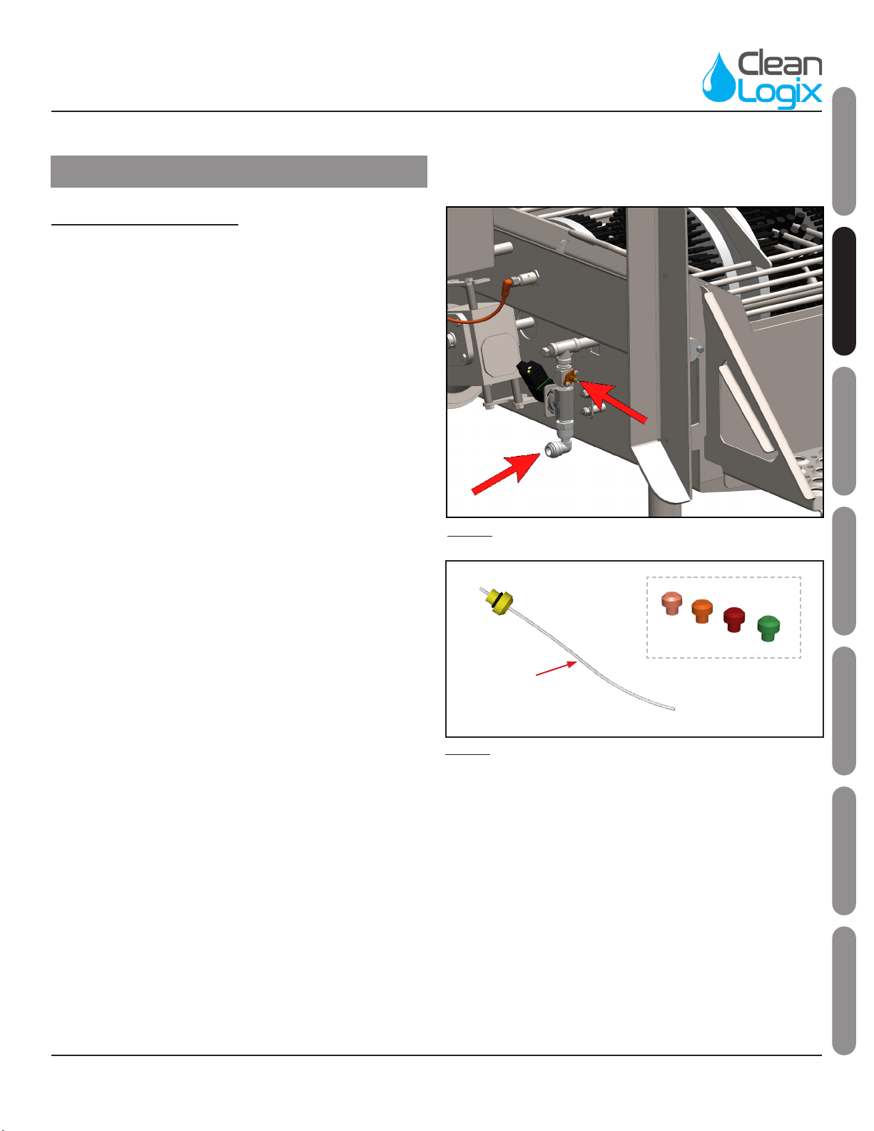
Plumbing Connecons:
1. Connect water source to solenoid valve quick ng
inlet using 1/2" Polyethylene tubing or similar [Figure
7.2].
2. If necessary, adjust the diluon rao by selecng an
appropriate metering p (included) and test.
• The smallest metering p is a yellow p with a
small tube aached [Figure 7.3].
• This tube can be trimmed to alter the diluon
rao.
• Full length capillary tube results in a diluon rao
of approximately 1:670 at 30-50 psi water inlet
pressure.
3. With the metering p installed, connect soluon
source to orange hose barb of the Venturi Injector
(located above water inlet) using 1/4" clear PVC tubing
(included) [Figure 7.2].
Installaon (connued)
Fig. 7.1: Water and Venturi Injector (soluon) inlets
Capillary
Tube
Addional
Metering Tips
Fig. 7.2: Metering Tips and Capillary Tube
BLX-1000-GEN2 User Manual Page 8 of 29 Updated: 02/11/21
USER MANUAL: BLX-1000-GEN2
READ ALL INSTRUCTIONS BEFORE OPERATING EQUIPMENT
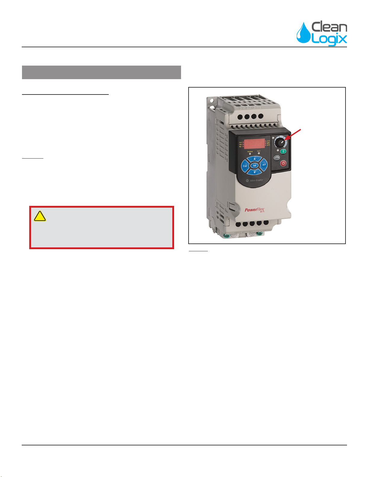
Motor Speed Adjustment
The speed of the motor is controlled by a variable
frequency motor drive. As the drive decreases the
frequency of the motor, the RPMs decrease. The V.F. drive
displays the Hz. on a small display and the knob next to it
adjusts the Hz. The worm gear reducer has a 20:1 rao.
Default: 1750 RPM at 60 Hz.
To adjust the speed:
1. Open the control box.
2. Acvate the sensor to turn on the motor.
3. As the motor is spinning, the unit will display the
operang speed in Hz.
4. Turn the knob counter-clockwise to decrease the Hz,
therefore decreasing the RPMs. Turning the knob
clockwise will increase the RPMs [Figure 8.1]
5. Adjust the Hz. on the variable frequency drive to the
desired brush speed. The minimum frequency is 15 Hz
and the maximum is 60 Hz Clean Logix recommends 70
RPM/48 Hz.
Installaon (connued)
!
DANGER:
Do not open control box during wash down
or cleaning. Only authorized personnel should
open the control box.
Speed
Adjustment
Fig. 8.1: PowerFlex 4M Variable Frequency Drive
BLX-1000-GEN2 User Manual Page 9 of 29 Updated: 02/11/21
USER MANUAL: BLX-1000-GEN2
READ ALL INSTRUCTIONS BEFORE OPERATING EQUIPMENT
General
Installaon
OperaonAppendix Maintenance ConguraonTroubleshoong
Operaon
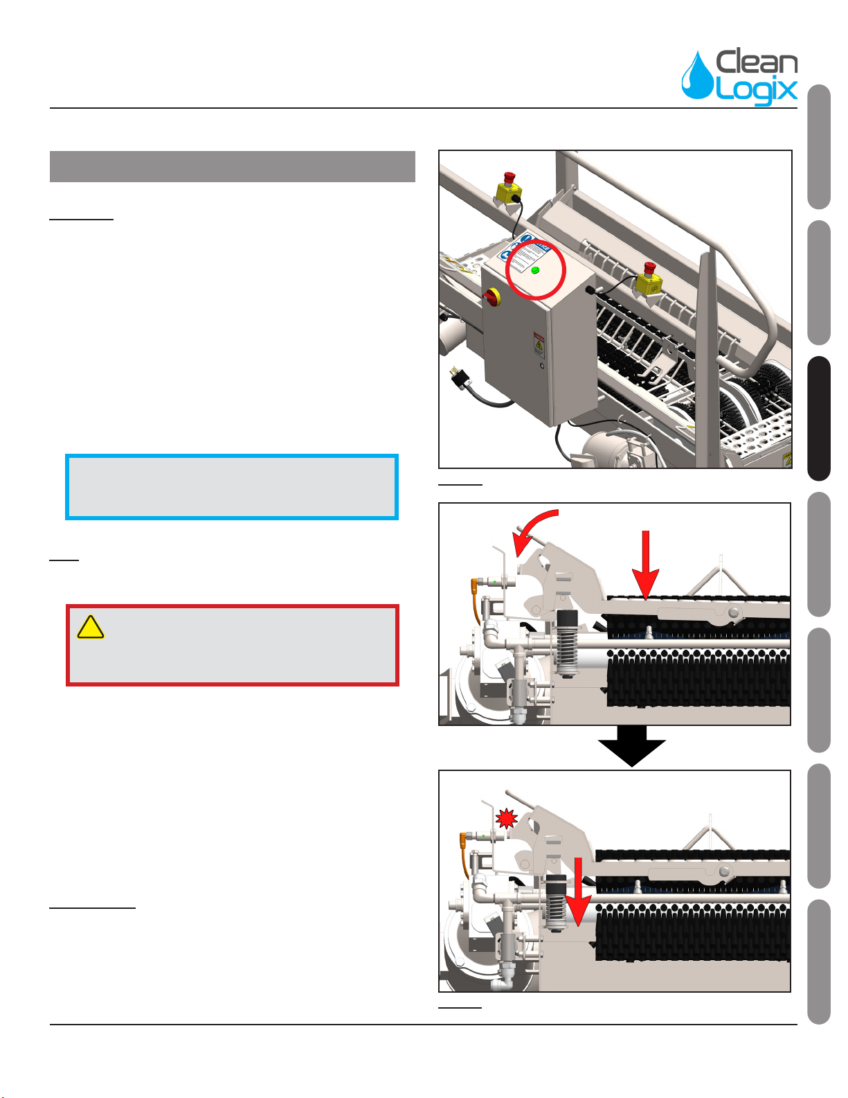
Fig. 9.2: Grate triggering Prox Switch, shown on BLX-1000S
Start Up
1. Verify installaon has been completed:
• Brushes are secure
• Walkway grate is lowered
• Unit is plugged in and receiving power
• Water and soluon have been plumbed and lines
are open
2. Pull the E-STOP switches up and engage power, when
the green light on control box is illuminated the unit is
receiving power [Figure 9.1].
Use
1. Step onto the walkway grate.
2. The walkway grate will depress, acvang a proximity
sensor which starts the brush rotaon and soluon
spray [Figure 9.2].
3. Walk through the unit, allowing the rotang brushes to
clean by moving the boot to make contact with hard to
reach areas.
4. One second aer the user steps o of the walkway
grate the brushes and sanizer will stop.
Shut Down
• Press the red E-STOP buon on the control box.
• Disconnect power and follow lockout-tagout
procedures as necessary.
!
CAUTION:
When operang: always ensure solid foong
and use both handrails for stability.
NOTE: Prior to placing footwear into the unit, test
that it is working properly by acvang the sensor
(put weight on the grate).
Fig. 9.1: Power indicator on control box, shown on BLX-1000R
BLX-1000-GEN2 User Manual Page 10 of 29 Updated: 02/11/21
USER MANUAL: BLX-1000-GEN2
READ ALL INSTRUCTIONS BEFORE OPERATING EQUIPMENT
Cleaning Procedures
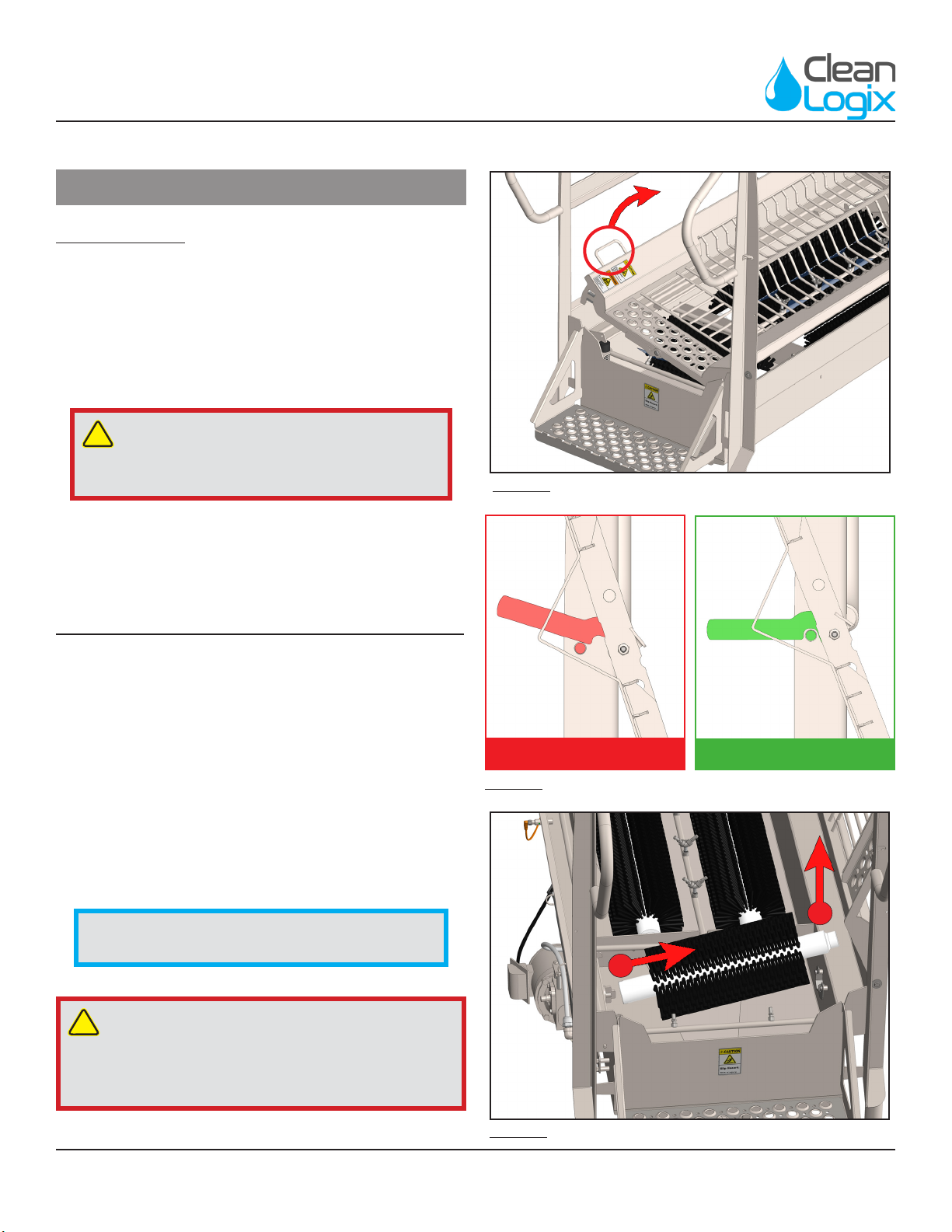
Opening Grate
1. Shut down the unit (see pg. 9) and li the grate up by
its handle [Figure 10.1].
2. Swing the grate open completely.
3. Latch into place against the pin aached to the corner
rail [Figure 10.2].
Fig. 10.1: Grate Liing, shown on BLX-1000S
!CAUTION:
Failure to latch the grate properly could result
in grate falling closed unexpectedly.
INCOMPLETE COMPLETE
Fig. 10.2: Grate Latch Orientaon
!
CAUTION:
Use of high pressure (above 400 PSI) is not
recommended on sensive areas such as electrical
components, motors, or gearboxes.
Removing & Replacing Brushes (R & SModels)
1. Shut down the unit and open the grate.
2. Li each brush out of the tub by grabbing the open
end and liing up [Figure 10.3 - Arrow 1].
3. With the open end lied, the brush can be detached
from its anchor [Figure 10.3 - Arrow 2].
4. Repeat this process to remove other brushes.
5. Brushes can be washed individually in a COP tank or
wash machine.
6. The tub can be washed by convenonal means.
NOTE: It is NOT recommended to use hot water
(over 120°F) to clean brushes.
Fig. 10.3: Brush removal process, shown on BLX-1000S
1
2

BLX-1000-GEN2 User Manual Page 11 of 29 Updated: 02/11/21
USER MANUAL: BLX-1000-GEN2
READ ALL INSTRUCTIONS BEFORE OPERATING EQUIPMENT
General
Installaon
OperaonAppendix Maintenance ConguraonTroubleshoong
Removing & Replacing Brushes (V Models)
1. Shut down the unit and open the grate (see pg. 9).
2. Remove the three vercal brushes by unscrewing the
stainless knobs at the top of each brush and liing
them up and o of their shas [Figure 11.1]
3. With the vercal brushes removed the sole brushes
can be released from their anchors. To release the sole
brushes: turn and pull the anchor lever located on the
side of the tub (opposite side of control box) as shown
below:
4. Li the rst sole brush out of the tub by grabbing the
open end and liing up to clear the opposing drive
sha anchor [Figure 11.2].
5. With the rst sole brush removed, the second brush's
drive sha anchor can be shied to remove the nal
sole brush [Figure 11.3].
6. Brushes can be washed individually in a COP tank or
wash machine.
7. The tub can be washed by convenonal means.
Cleaning Procedures (connued)
Fig. 11.1: Removing vercal brushes
NOTE: It is NOT recommended to use hot water
(over 120°F) to clean brushes.
Fig. 11.2: Removing soles brushes (1 of 2)
LOCKED UNLOCKED
Fig. 11.3: Removing soles brushes (2 of 2)
BLX-1000-GEN2 User Manual Page 12 of 29 Updated: 02/11/21
USER MANUAL: BLX-1000-GEN2
READ ALL INSTRUCTIONS BEFORE OPERATING EQUIPMENT
Cleaning Procedures (connued)
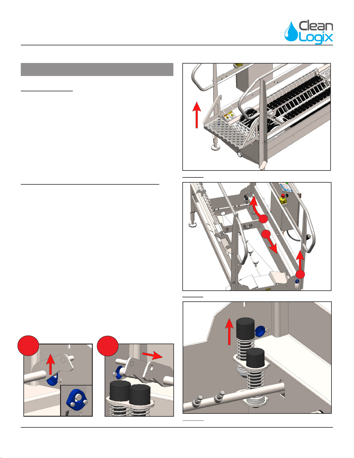
Removing Steps
1. Shut down the unit.
2. Grab either side of the step by the handles.
3. Li up to remove from tub [Figure 12.1].
4. Steps can be washed individually in a COP tank or wash
machine.
5. Replace steps before enabling power and/or use.
Removing Grate Spring Balancer & Springs
1. Open the Grate.
2. Li the end of the Spring Balancer into the upper
secon of its keyhole. [Figure 12.2 - Arrow 1]
3. Slide the Spring Balancer through the upper secon
of the keyhole to release its other end. [Figure 12.2 -
Arrow 2]
4. Li the free end up while sliding the Spring Balancer
out the keyhole to remove from the tub. [Figure 12.2 -
Arrow 3]
5. Slide each spring up to remove them from the tub
[Figure 12.3].
6. Springs and Balancer Weldment can be washed
individually in a COP tank or wash machine.
Fig. 12.1: Step removal, shown with BLX-1000R
Fig. 12.2 Balancer Weldment removal procedure
Fig. 12.3: Spring removal procedure
3
2
2
1
1
BLX-1000-GEN2 User Manual Page 13 of 29 Updated: 02/11/21
USER MANUAL: BLX-1000-GEN2
READ ALL INSTRUCTIONS BEFORE OPERATING EQUIPMENT
General
Installaon
OperaonAppendix Maintenance ConguraonTroubleshoong
Advanced Conguraon Opons
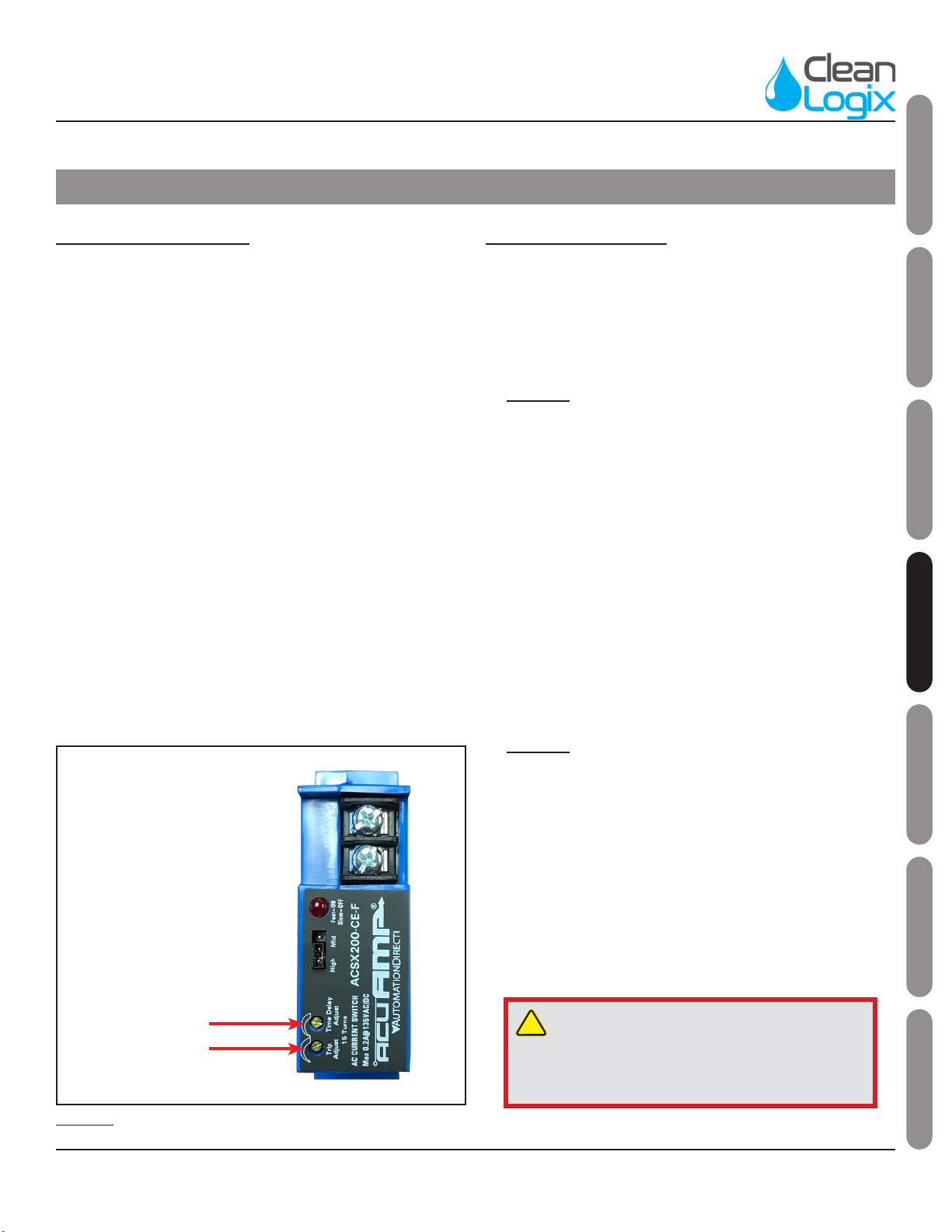
Motor Current Sensor
The motor current sensor monitors the current draw of the
motor and will stop the motor if an over-torque condion
occurs, resulng in an F002 fault code on the VFD.
Default Set Point = 10 turns clockwise
Raise the Set-Point:
1. Turn screw clockwise ½ turn and test
To Start Over:
1. Turn screw counter-clockwise unl it clicks.
2. Turn the screw clockwise 10 turns and test.
The sensor also features a me delay that is adjustable
from 0.12 to 15 seconds. The current draw of the motor
MUST exceed the me delay set point connuously for this
duraon in order for a fault to occur.
Default Time Delay = 1/8 turn (about 0.3sec / 300ms)
!
DANGER:
Do not open control box during wash down
or cleaning. Only authorized personnel should
open the control box.
Brush RPM Formula:
The formula for calculang Speed in RPM from Drive
Frequency in Hertz is:
[Motor Nameplate RPM] x [Drive Frequency (Hz)] ÷ [Motor
Nameplate Frequency (Hz)] ÷ [Gear Reducon]
Example:
• Motor Nameplate RPM = 1750
• Motor Nameplate Frequency (Hz) = 60
• Gear Reducon = 20
• Drive Frequency (Hz) = 48
1750 x 48 ÷ 60 ÷ 20 = 70 RPM
The formula for calculang Drive Frequency in Hertz from
Desired Speed in RPM is:
[Desired Speed RPM] x [Gear Reducon] x[Motor
Nameplate Frequency (Hz)] ÷[Motor Nameplate RPM]
Example:
• Desired Speed in RPM = 70
• Gear Reducon = 20
• Motor Nameplate Frequency (Hz) = 60
• Motor Nameplate RPM = 1750
70 x 20 x 60 ÷ 1750 = 48 Hz
SET-POINT
Fig. 13.1: Current Sensor Sengs Idencaon
TIME DELAY
BLX-1000-GEN2 User Manual Page 14 of 29 Updated: 02/11/21
USER MANUAL: BLX-1000-GEN2
READ ALL INSTRUCTIONS BEFORE OPERATING EQUIPMENT
Advanced Conguraon Opons (connued)
Drive Parameter Sengs
PowerFlex 4M Variable Frequency Drive
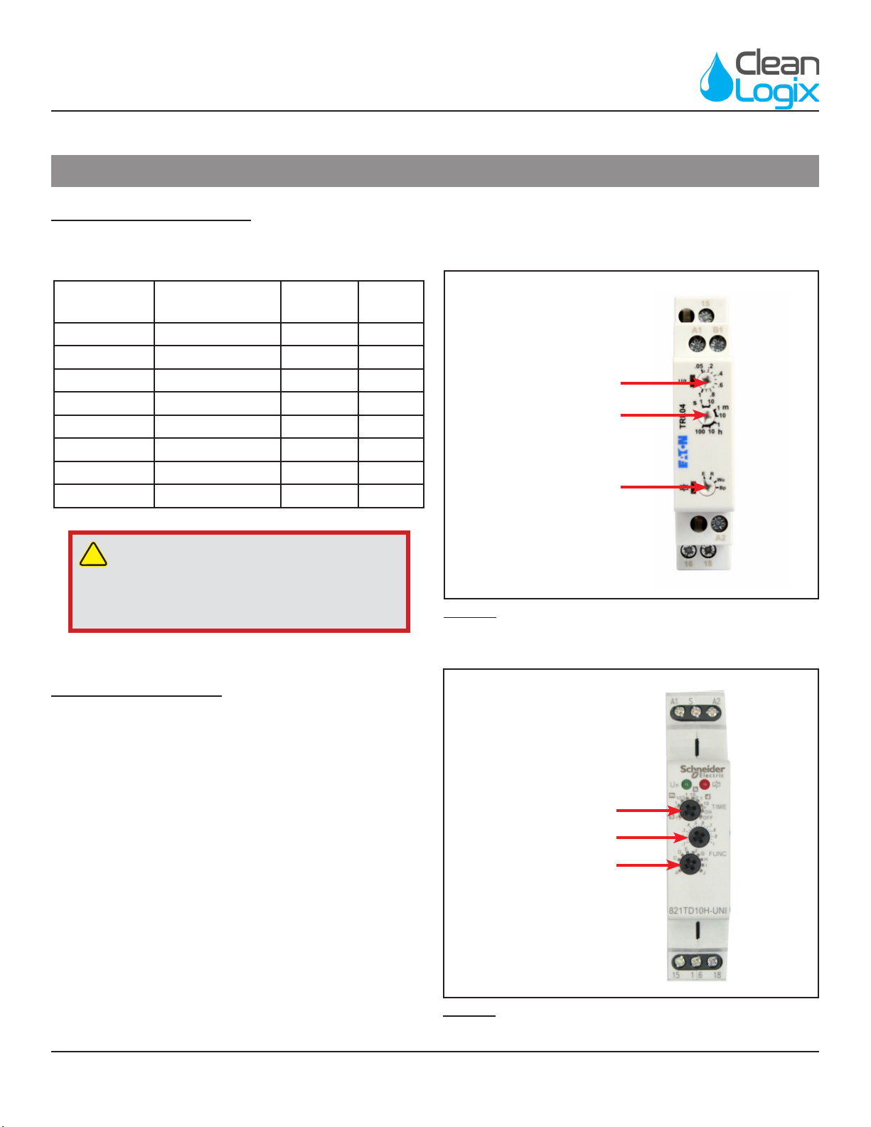
Timing Relay Sengs
Eaton TRL04
• Funcon: R (O Delay)
• Time Range: 1 sec.
Schneider Electric Magnecra
• Funcon: S (O Delay)
• Time Range: 1 sec.
FUNCTION
TIME RANGE
ADJUSTMENT RANGE
Fig. 14.1: Eaton TRL04 Seng Idencaon
Parameter
Number Descripon Seng Units
P102 Motor NP Hertz 60 Hz
P104 Minimum Freq 30 Hz
P105 Maximum Freq 60 Hz
P106 Start Source 2N/A
P109 Accel Time 1 s
P110 Decel Time 2 s
t201 Digital In 1 Sel 3N/A
t221 Relay Out Sel 1 N/A
!
DANGER:
Do not open control box during wash down
or cleaning. Only authorized personnel should
open the control box.
FUNCTION
TIME RANGE
ADJUSTMENT RANGE
Fig. 14.2: Schneider Magnecra Seng Idencaon
BLX-1000-GEN2 User Manual Page 15 of 29 Updated: 02/11/21
USER MANUAL: BLX-1000-GEN2
READ ALL INSTRUCTIONS BEFORE OPERATING EQUIPMENT
General
Installaon
OperaonAppendix Maintenance ConguraonTroubleshoong
The following maintenance procedures are recommended
for normal use. Units which see a high amount of daily use
should be inspected more frequently as necessary.
Weekly:
• Check unit for proper sensor funcon and brush
rotaon.
• Ensure spring loaded grate (if applicable) is
funconing properly.
• Inspect brushes for damage or wear. Check for
missing or deformed bristles.
• Inspect electrical cords and plumbing for damage.
• Inspect and test funcon of emergency stop
switches.
Monthly:
• Check all fasteners to ensure they are ght.
• Ensure warning labels and decals are present and in
good condion.
• Inspect motors, gearboxes, and reducers for signs of
oil leakage.
• Inspect electrical enclosure for signs of water
intrusion.
• Inspect sensors for damage.
• Inspect moving parts for damage or wear.
Quarterly:
• Inspect structure for cracked welds or bent
components.
Gear Reducer:
• The gear reducer is supplied lled to capacity with
Mobil Cibus SHC 634 NSF H1 Food Grade or equal
synthec oil.
• The synthec lubricaon provided is good for
ambient temperatures -10°F - 105°F and is
compable with standard compounded oil.
• Oil should be changed every 2 years (or 6,000
operang hrs.)
• Designed with a bladder type vent system:
• Consists of an internal bladder that seals the
oil chamber from the outside environment
at all mes - as pressure builds, the bladder
contracts keeping the internal pressure to a
minimum.
• Advantage: The internal oil chamber is
completely sealed, ensuring oil is not released
causing contaminaon in the applicaon.
Motor:
• Inspect at regular intervals.
• Keep clean and venlang openings (on TEFC
motors) clear of any obstrucons.
• Verify the mounng bolts and couplings to ensure
that they are ght and properly adjusted.
• Motor bearings are sealed and not
re-greasable.
• Bearings should be replaced approximately every 5
years for 8 hr./day service.
Preventave Maintenance
NOTE: Control box is equipped with a Lock-Out/
Tag-Out switch for restricted power access when
performing maintenance procedures.

BLX-1000-GEN2 User Manual Page 16 of 29 Updated: 02/11/21
USER MANUAL: BLX-1000-GEN2
READ ALL INSTRUCTIONS BEFORE OPERATING EQUIPMENT
Unit will not operate:
• Follow the startup procedure (pg. 9)
• Verify the control box is closed and the power-
disconnect switch is in the ON posion.
• Verify that there is power going to the unit.
• Verify the circuit breakers in the building have
not been tripped.
Unit will not spray:
• Verify water pressure at the inlet to the water/
soluon solenoid (35 psi min.)
• Inspect spray nozzles for clogging.
• Verify that the orange LED light on the solenoid valve
connector illuminates when the brushes are rotang.
Green START buon is illuminated, but one
or more brushes will not rotate when unit is
acvated:
• Power cycle the unit by turning the disconnect
switch to OFF and then back to ON. Follow the start
up procedure on Page 9.
Troubleshoong
Unit is leaking onto oor:
• Check to make sure all joints are sealed.
• Verify water and soluon inlets are aached and rmly
in place.
Leaner Diluon Raos Required:
• Verify metering p is installed in the injector chemical
inlet hose barb
• Use the yellow “Capillary Tube” style metering p (see
pg. 7 for further informaon)
• If the desired diluon rao sll cannot be achieved
pre-diluon of the chemical may be necessary.
Venturi will not draw Chemical Soluon:
• Verify water supply is sustaining 30 psi at the injector
inlet while unit is running
• Elevate the chemical jug above the injector (a jug hook
is provided for this purpose)
• Verify spray nozzles are not clogged. The nozzles
supplied with the equipment are rated at 0.2GPM @
10psi (0.28GPM @ 20 psi)
• Ensure the sucon lter is not clogged, kinked or
obstructed in any way that would restrict ow.

BLX-1000-GEN2 User Manual Page 17 of 29 Updated: 02/11/21
USER MANUAL: BLX-1000-GEN2
READ ALL INSTRUCTIONS BEFORE OPERATING EQUIPMENT
General
Installaon
OperaonAppendix Maintenance ConguraonTroubleshoong
F002 Fault Code on Variable Frequency Drive:
Cause: Power may have been cycled to the unit while it
was “ON”. To solve:
1. While power is sll applied, turn the unit “o” by
pushing down hard on the e-stop buon
2. Wait at least 5 seconds, then pull the e-stop buon
out again. DO NOT stand on the walkway grate
during this process.
3. The unit should now be ready for use.
Cause: If the brushes stop suddenly during normal use
and the fault is displayed, the Motor Current Sensor set
point may be too low. To solve:
1. Turn the set point adjusng screw clockwise ½ turn
to raise the set point and re-test.
F004 Fault Code on Variable Frequency Drive:
• If unit is connected to a GFCI, verify its rangs (class,
mA restricons, etc.)
• Verify minimum frequency seng on VFD is set
between 15 to 20 Hz.
• VFD Parameter: P104 [Minimum Freq.]
• Manufacturer Default: 30 Hz.
• Set the lowest carrier frequency on the VFD (lower
carrier = less switching on/o)
• VFD Parameter: P446 [PWM Frequency]
• Manufacturer Default: 4.0 kHz.
• Minimum: 2.0 kHz.
Troubleshoong
NOTE: Clean Logix recommends Leviton's GFI
protecon device [# GFRBF-W] for circumstances
where the facility's original GFCI plug is not
applicable.

BLX-1000-GEN2 User Manual Page 18 of 29 Updated: 02/11/21
USER MANUAL: BLX-1000-GEN2
READ ALL INSTRUCTIONS BEFORE OPERATING EQUIPMENT
Appendix A - Parts Callout (BLX-1000R-GEN2 : Regular)
BLX-1000-GEN2 User Manual Page 19 of 29 Updated: 02/11/21
USER MANUAL: BLX-1000-GEN2
READ ALL INSTRUCTIONS BEFORE OPERATING EQUIPMENT
General
Installaon
OperaonAppendix Maintenance ConguraonTroubleshoong
Appendix A - Parts Callout (BLX-1000R-GEN2 : Regular)
Part No. Descripon
F1000 STANDOFF 1/4 X 1/2 X 1/2 SS
F1040 BOLT SHCS 5/16-18 X 1-1/4 SS
F1044 NUT NYLOCK 8-32 SS
F1047 NUT NYLOCK 1/4-20 SS
F1052 NUT NYLOCK 5/16-18 SS
F1056 WASHER 1/4 SS TYPE A
F1066 NUT NYLOCK 10-32 SS
F1078 WASHER1/2" X 7/8" X 1/16" UHMW
F1083 BOLT HHC 1/4-20 X 1-1/4 SS
F1085 WASHER FENDER 5/16 SS
F1088 BOLT HHC 1/4-20 X 1-3/4 SS
F1126 BOLT HHC 10-32 X 1 SS
F1130 BOLT HHC 5/16-18 X 5/8" SS
F1135 STANDOFF 1/4 X 1/2 X 3/16 SS
F1136 STANDOFF 1/4 X 1/2 X 1 SS
F1139 BOLT SHUTTER 1/4-20 X 1 SS
F1146 SCREW 8-32 X 3/4 SS PHILLIPS PAN HD
F1166 BOLT HHC 5/16-18 X 2-1/4 SS
M1080 HORIZONTAL BRUSH BLX-1000
M1134 SOLENOID BRACKET
M1183 DRIVE SHAFT MOTOR-BRUSH WELDMENT
M1186 COMBINATION BRUSH ASSEMBLY
M1237 GRATE LATCH
M1420 BRUSH SUPPORT WELDMENT
M1534 SPACER .313 X .5 X 1.5 SS
M1746 JUG HOOK V2
M1758 GRATE STEPPED HINGE PIN
M1795 BLX FORMED STEP 24 INCH
M1830 BLX-1000 GEN2 TUB WELDMENT
M1843 BLX-1000 GEN2 ELECTRICAL ASSY 230V 1PH
M1845 BLX GEN2 SPRAY MANIFOLD WELDMENT - R
AND S MODELS
M1848 BLX-1000 GEN2 SPRAY MANIFOLD WELDMENT
M1850 BLX-1000 GEN2 SPRAY NOZZLE RISER
WELDMENT
M1851 BLX-1000 GEN2 PIPE NIPPLE
M1852 BLX-1000 GEN2 MOTOR COVER
NOTE: For brush replacement orders reference Part # BLX-1000R-CBS
Part No. Descripon
M1893 BLX-1000 GEN2 SPRING BALANCER WELDMENT V3
M1894 BLX C-CHANNEL GRATE LIFT PIN GLIDE
M1896 BLX GEN2 GRATE SPRING ASSEMBLY
M1904 BLX GEN2 SPRING BALANCER BEARING ROUND
M1905 BLX GEN2 SPRING BALANCER BEARING SLOTTED
M1950 BLX-1000R GEN2 GRATE V3 WELDMENT
P1005 MOTOR 1/2 HP 1750RPM SS 56C
P1005 MOTOR 1/2 HP 1750RPM SS 56C
P1006 GEAR REDUCER 20:1 5/8 SS
P1046 SOLENIOD SS BODY 3/8"
P1109 PIPE ELBOW STREET 3/8" SS
P1121 PROXIMITY SENSOR 18mm
P1147 CORD GRIP 1/2 NPT X .170 - .450 BLK
P1148 CORD GRIP NUT 1/2 NPS NYL
P1184 CORD GRIP 1/2 NPT X .095-.260 BLK
P1187 SOLENOID CABLE 18mm DIN 24V
P1242 TERMINAL, 1/4" RING, 14-16 AWG INS
P1250 EMERGENCY STOP UNIT
P1331 TUBING, 1/2" OD POLYETHYLENE
P1400 CABLE M12 4-POLE 5m IP69K
P1418 QUICK FIT 3/8 NPT X 1/2 TUBE
P1511 QUICK FIT STEM ELBOW 1/2" X 1/2"
P1599 METERING TIP, CAPILLARY TUBE
P1769 METERING TIPS, ULTRA LEAN
P1825 PIPE COUPLER 3/8" 304SS
P1828 WIRE, VFD-MOTOR, 14 AWG, 4-CONDUCTOR,
SHIELDED, XLPE/PVC
P1904 VENTURI INJECTOR DEMA ROCKET, DARK GREEN,
.125", 3.7GPM AT 100PSI, SINGLE BARB
P1934 GREASE, ELECTRIC INSULATING .17OZ ONE TIME
USE PACK
P1944 NOZZLE, FAN SPRAY, 110 DEGREE, 1/8 MNPT, 0.2
GPM AT 10PSI (1/8KSS-2)
P1945 VENTURI INJECTOR 1/4" SUCTION LINE AND
STRAINER
P1946 VENTURI INJECTOR SUCTION WEIGHT CERAMIC
FOR 1/4" TUBE

BLX-1000-GEN2 User Manual Page 20 of 29 Updated: 02/11/21
USER MANUAL: BLX-1000-GEN2
READ ALL INSTRUCTIONS BEFORE OPERATING EQUIPMENT
Appendix A - Parts Callout (BLX-1000S-GEN2 : Sole)
Table of contents
Other Clean Logix Cleaning Equipment manuals

Clean Logix
Clean Logix ALX-OMNI-LITE User manual

Clean Logix
Clean Logix ALX-PRO User manual

Clean Logix
Clean Logix BLX-700-GEN2 User manual

Clean Logix
Clean Logix BLX-400 User manual

Clean Logix
Clean Logix EPX-TM User manual

Clean Logix
Clean Logix BLX-800-GEN2 User manual

Clean Logix
Clean Logix BLX-600-GEN2 User manual

Clean Logix
Clean Logix BLX-900S-GEN2 User manual


