manuals.online logo
Brands
  1. Home
  2. •
  3. Brands
  4. •
  5. CLEAR DESIGN
  6. •
  7. Indoor Furnishing
  8. •
  9. CLEAR DESIGN BHA2GSA User manual

CLEAR DESIGN BHA2GSA User manual

BHA2GSA/BHA3GSA
BOOST
HEIGHT-ADJUSTABLE
WORKSTATION
Includes Add-Ons: A1 | A2 | A3 | A4
General Installation Guide
TABLE OF CONTENTS
EDITION CODE
BHA :: Workstation..................................................................1
ADD-ONS
A1 :: Casters...............................................................................9
A2 :: Modesty Panel.............................................................. 13
A3 :: Slim Pedestal.................................................................17
A4 :: Cable Tray ..................................................................... 21
WORKSTATION
OVERVIEW
BOOST Height-Adjustable Workstation
All parts listed are for a single workstation;
additional parts will be needed for additional
workstations.
1
2
WORKSTATION
CODE QTY DESCRIPTION
###### 1Surface
BHA3GSA
or
BHA2GSA
1Center-Adjustable Beam
1Feet (Set of 2)
223"Arm Bracket
2Leg with Motor
1Handset
1Short & Long Extension Cord
1Power Cable
8Screw (A)
24 Screw (B)
3Screw (C)
8Screw (D)
BHANBEAM* 1BOOST Replacement Beam
BHA19* 219"Arm Bracket
TLEG.
ADAPTGSA* 1T-Leg Adapter (Set of 2)
BASB72* 142"Support Bar
PARTS LIST
*If applicable.
3
WORKSTATION
1 | DETERMINE SURFACE SIZE FOR INSTALLATION
Use the chart below to identify which arm brackets will be used with
surface size, and if surface will need replacement beam (BHANBEAM).
Note: Reference STEP 4 after completing STEP 2 and 3.
Surface
Depth
Surface
Width
Including
Surface
Dividers?
Arm
Bracket
Type
BHANBEAM Reference
Step 4
24" 36"-47" No Default Yes A
24" 36"-47" Yes BHA19 Yes B
24" 48" No Default No C
24" 48" Yes BHA19 No D
24" 5 4"-72 " No Default No E
24" 5 4"-72 " Yes Default No F
30" 36"-47" Yes / No Default Yes
G
30" 5 4"-72 " Yes / No Default No
4
WORKSTATION
2 | ASSEMBLE WORKSTATION FRAME
Attach legs with motor and arm brackets to the center beam using
screws (A).
Note: Replace the default arm brackets if workstation requires BHA19 or
T-brackets. Surface width 36"-47" will need to replace the beam, without
the control box, with BOOST replacement beam (BHANABEAM).
3 | PLACE FRAME ON THE SURFACE
Loosen existing locking screws on adjustable beam to extend beam to fit table
size. Run cord through cutout from the adjustable beam and secure the
handset to control box. Attach the short extension cord to the motor closest
to control box and attach the longer extension cord on the opposite end.
Short Ext. Cord
Long Ext. Cord
Locking Screws
BHANABEAM
BHA19
5
WORKSTATION
4 | ADJUST FRAME ON SURFACE
Note: Based on STEP 1 surface size chart, reference one of the following
workstation diagrams to secure frame.
(A) 24"D x 36"–47"W Surfaces without Side Dividers
Extend the frame equal to the surface width. Center arm brackets in reference
to surface depth. Secure frame to surface using wood screws (B) and secure
handset using wood screws (C).
(B) 24"D x 36"–47"W Surfaces with Side Dividers
If using side dividers, frame will include arm brackets BHA19. Extend the frame
equal to the surface width. Center arm brackets in reference to surface depth.
Secure frame to surface using wood screws (B) and secure handset
using wood screws (C).
BHA19 Brackets
6
WORKSTATION
(C) 24"D x 48"W and Smaller Surfaces without Side Dividers
Extend the frame equal to the surface width. Center arm brackets in reference
to surface depth. Secure frame to surface using wood screws (B) and secure
handset using wood screws (C).
(D) 24"D x 48"W and Smaller Surfaces with Side Dividers
If using side dividers, frame will include arm brackets BHA19. Extend the frame
equal to the surface width. Center arm brackets in reference to surface depth.
Secure frame to surface using wood screws (B) and secure handset
using wood screws (C).
BHA19 Brackets
7
WORKSTATION
(E) 24"D x 54"–72"W Surfaces without Dividers
Extend the frame equal to the surface width. Center arm brackets in reference to
surface depth. Secure frame to surface using wood screws (B) and secure
handset using wood screws (C).
(F) 24"D x 54"–72"W Surfaces with Side Dividers
If using side dividers, inset the frame 2” from each end. Center arm brackets to
surface depth. Secure frame to surface using wood screws (B) and secure
handset using wood screws (C).
Note: If using side dividers AND a facing divider with BSBHL, replace the
arm brackets with BHA19.
2" 2"
8
END OF WORKSTATION SECTION
(G) 30" Deep Surfaces
Extend the frame equal to the surface width. Center arm brackets to surface
depth. Secure frame to surface using wood screws (B) and secure handset
using wood screws (C).
5 | SECURE POWER CORD & INSTALL FEET
Secure power cord to the control box. Secure locking screws on the adjustable
beam and install the feet using screws (D) for each leg. If workstation is complete,
flip over. Reference handset guide for initialization and operation functions.
Note: Use T-feet if using T-arm brackets.
A1: CASTERS
OVERVIEW
BOOST Height-Adjustable Workstation
All parts listed are for a set of 4 casters;
additional parts will be needed for additional casters.
9
10
CASTERS
CODE QTY DESCRIPTION
BHACAST
1Caster Kit (Set of 4)
16 Screws
PARTS LIST
11
CASTERS
1 | REMOVE GLIDES FROM FEET
Unscrew all four glides from feet and disregard.
12
END OF CASTERS SECTION
2 | ATTACH CASTERS TO FEET
The workstation’s feet have pre-drilled holes for the caster plate. Attach casters
using self-tapping metal screws.
A1: MODESTY PANEL
OVERVIEW
BOOST Height-Adjustable Workstation
All parts listed are for a single modesty panel;
additional parts will be needed for additional
modesty panels.
13
14
MODESTY PANEL
CODE QTY DESCRIPTION
GLMP##
1Laminate Modesty Panel*
4Machine Screws
BMPBFB
2L- B r a c k e t s
4Wood Screws
PARTS LIST
*For Steel Modesty Panel: components may vary, but process is similar.
15
MODESTY PANEL
1 | SECURE BRACKETS TO MODESTY PANEL
Connect the BMPBFB bracket to the modesty panel using screws.
Secure tightly.
16
END OF MODESTY PANEL SECTION
2 | ATTACH MODESTY PANEL TO SURFACE
Attach modesty panel to surface using wood screws provided with brackets.
Panel will be center aligned and flushed with back of surface.
A2: SLIM PEDESTAL
OVERVIEW
BOOST Height-Adjustable Workstation
All parts listed are for a single slim pedestal;
additional parts will be needed for additional slim
pedestals.
17

This manual suits for next models

1

Other CLEAR DESIGN Indoor Furnishing manuals
CLEAR DESIGN EDGE ESHA User manual

CLEAR DESIGN

CLEAR DESIGN EDGE ESHA User manual

CLEAR DESIGN COVE CV-1 Configuration guide

CLEAR DESIGN

CLEAR DESIGN COVE CV-1 Configuration guide

CLEAR DESIGN COVE CV-2 Configuration guide

CLEAR DESIGN

CLEAR DESIGN COVE CV-2 Configuration guide

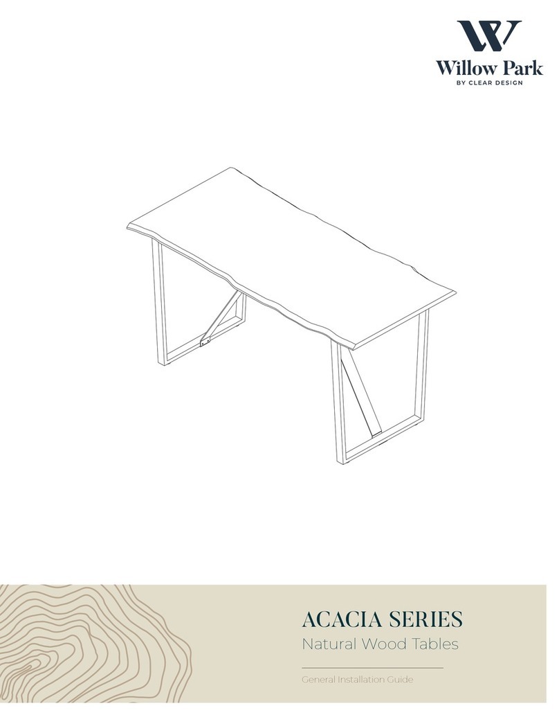
CLEAR DESIGN Willow Park ACACIA Series User manual

CLEAR DESIGN

CLEAR DESIGN Willow Park ACACIA Series User manual

CLEAR DESIGN BLCC Series User manual

CLEAR DESIGN

CLEAR DESIGN BLCC Series User manual

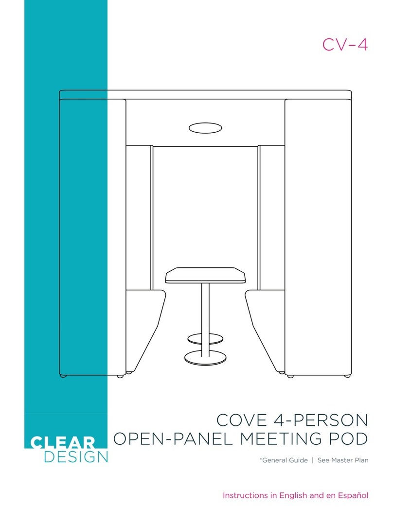
CLEAR DESIGN COVE CV-4 Configuration guide

CLEAR DESIGN

CLEAR DESIGN COVE CV-4 Configuration guide

CLEAR DESIGN EDGE ECH2472 User manual

CLEAR DESIGN

CLEAR DESIGN EDGE ECH2472 User manual

CLEAR DESIGN EDGE CASEGOODS EBDF3571 User manual

CLEAR DESIGN

CLEAR DESIGN EDGE CASEGOODS EBDF3571 User manual

CLEAR DESIGN BLLBFV2 User manual

CLEAR DESIGN

CLEAR DESIGN BLLBFV2 User manual

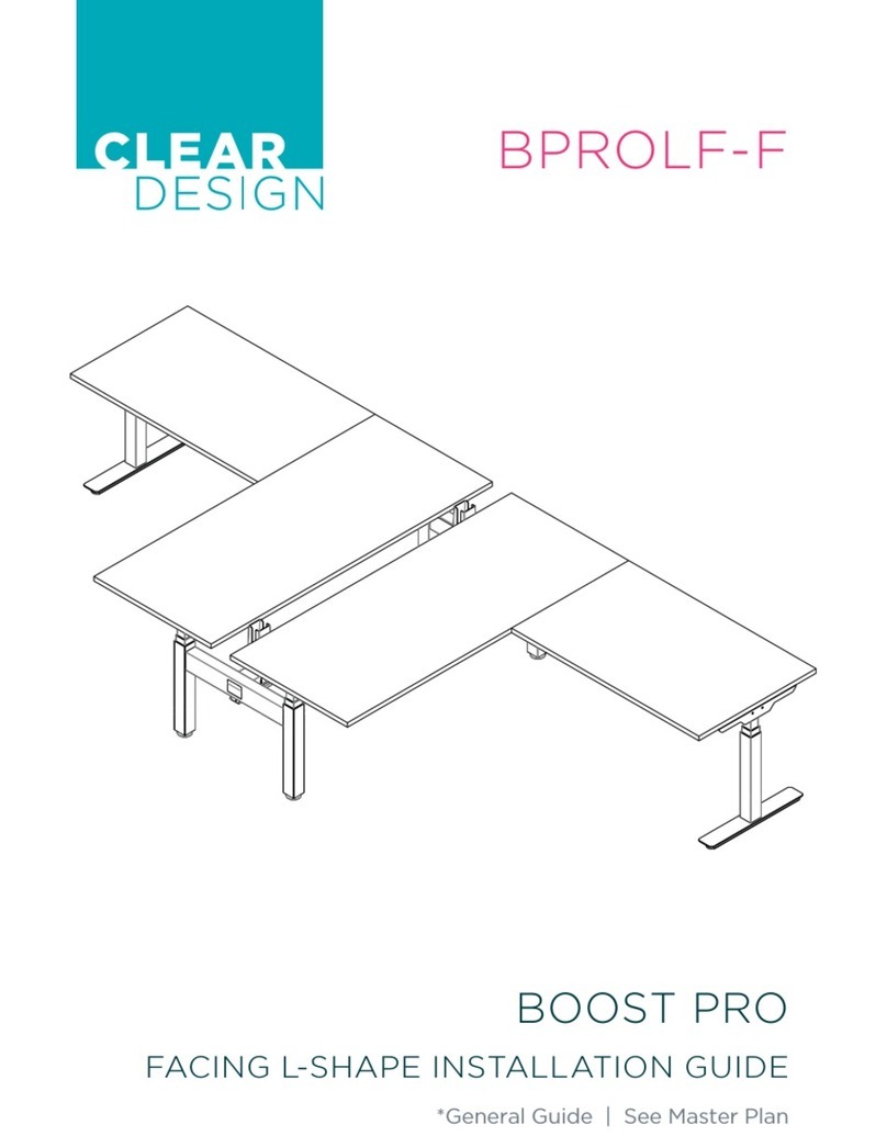
CLEAR DESIGN BOOST PRO BPROLF-F User manual

CLEAR DESIGN

CLEAR DESIGN BOOST PRO BPROLF-F User manual

CLEAR DESIGN KIT-BLBC72 User manual

CLEAR DESIGN

CLEAR DESIGN KIT-BLBC72 User manual

CLEAR DESIGN BLLBFV2 User manual

CLEAR DESIGN

CLEAR DESIGN BLLBFV2 User manual

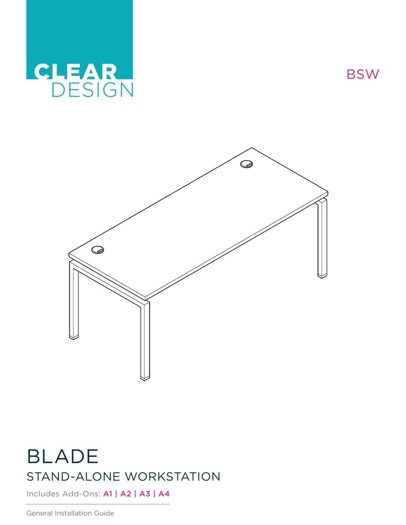
CLEAR DESIGN BLADE BSW User manual

CLEAR DESIGN

CLEAR DESIGN BLADE BSW User manual

CLEAR DESIGN BL-3 Configuration guide

CLEAR DESIGN

CLEAR DESIGN BL-3 Configuration guide

CLEAR DESIGN COVE CV-3 Configuration guide

CLEAR DESIGN

CLEAR DESIGN COVE CV-3 Configuration guide

CLEAR DESIGN BOOST PRO BP-1 User manual

CLEAR DESIGN

CLEAR DESIGN BOOST PRO BP-1 User manual

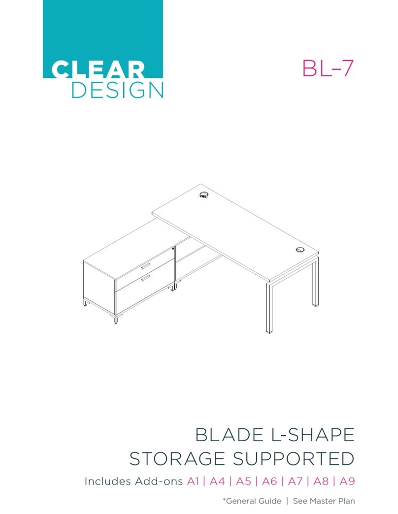
CLEAR DESIGN BL-7 User manual

CLEAR DESIGN

CLEAR DESIGN BL-7 User manual

CLEAR DESIGN BLLOSV2 User manual

CLEAR DESIGN

CLEAR DESIGN BLLOSV2 User manual

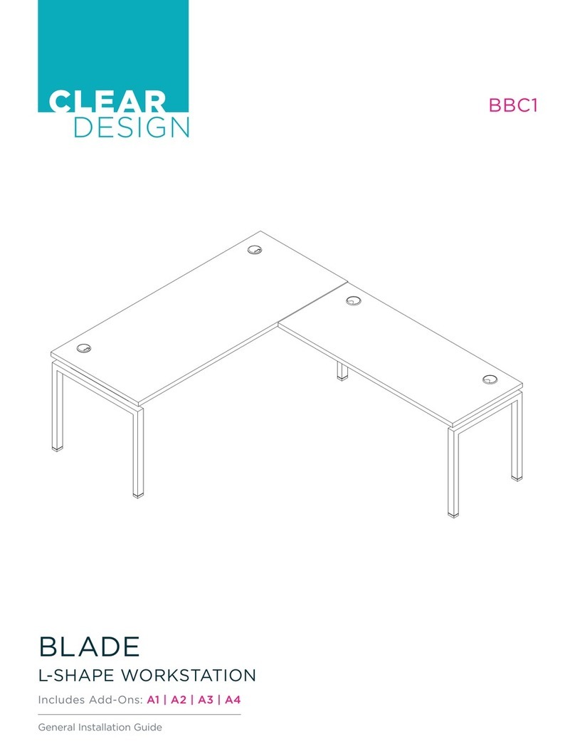
CLEAR DESIGN BLADE BBC1 User manual

CLEAR DESIGN

CLEAR DESIGN BLADE BBC1 User manual

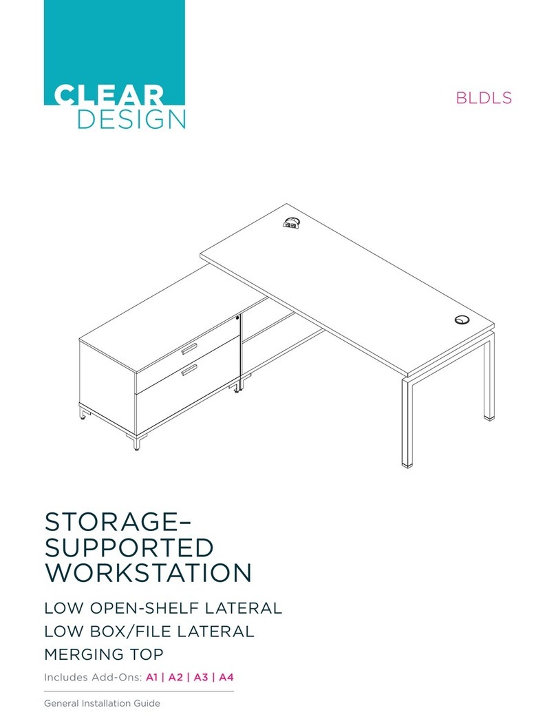
CLEAR DESIGN BLDLS User manual

CLEAR DESIGN

CLEAR DESIGN BLDLS User manual

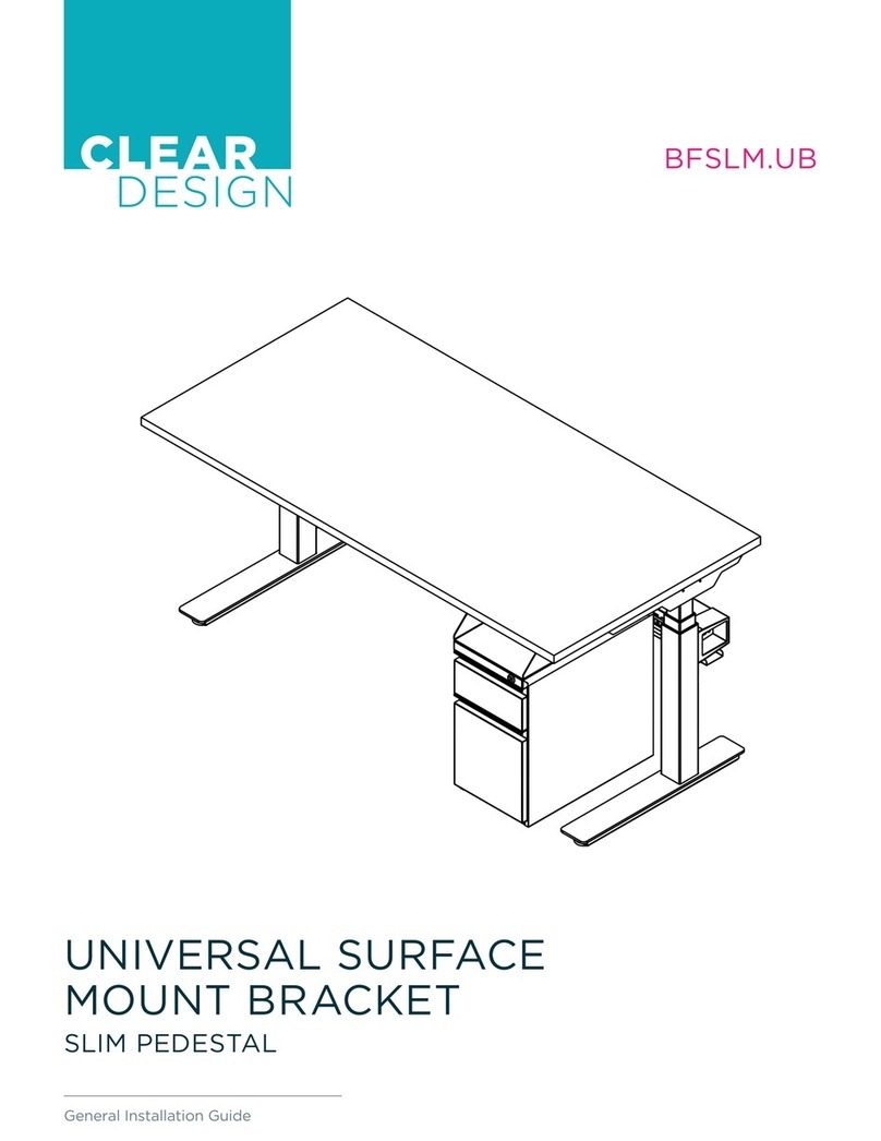
CLEAR DESIGN BFSLM.UB User manual

CLEAR DESIGN

CLEAR DESIGN BFSLM.UB User manual
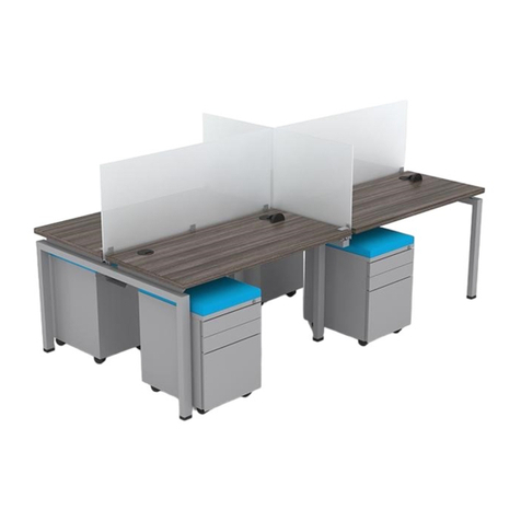
CLEAR DESIGN EDGE CASEGOODS EDF3059 User manual
CLEAR DESIGN

CLEAR DESIGN EDGE CASEGOODS EDF3059 User manual

CLEAR DESIGN THREE60 User manual

CLEAR DESIGN

CLEAR DESIGN THREE60 User manual

Popular Indoor Furnishing manuals by other brands
sweeek. BUDAPEST IBUDBUFFET manual

sweeek.

sweeek. BUDAPEST IBUDBUFFET manual

&Tradition MEZCLA JH21 User instructions

&Tradition

&Tradition MEZCLA JH21 User instructions

Schildmeyer Venlo 651400 Assembly instructions

Schildmeyer

Schildmeyer Venlo 651400 Assembly instructions

FURNITUREBOX JUNIPER Assembly guide

FURNITUREBOX

FURNITUREBOX JUNIPER Assembly guide

Forte BBLK121 Assembly instructions

Forte

Forte BBLK121 Assembly instructions

pottery barn kids MARLOW CRIB quick start guide

pottery barn kids

pottery barn kids MARLOW CRIB quick start guide

Kimball Office Xsede Height Adjustable instruction manual

Kimball Office

Kimball Office Xsede Height Adjustable instruction manual

DUSK Windsor Ottoman Bed Frame manual

DUSK

DUSK Windsor Ottoman Bed Frame manual

pelipal CS-SPS04 installation guide

pelipal

pelipal CS-SPS04 installation guide

DURAVIT XViu XV 7037 Mounting instructions

DURAVIT

DURAVIT XViu XV 7037 Mounting instructions

World Market 582731 Assembly instructions

World Market

World Market 582731 Assembly instructions

RB RELIABILT LS-SW-B27B Assembly instructions
RB RELIABILT

RB RELIABILT LS-SW-B27B Assembly instructions
Essential Home Faux Leather Upholstered Bed Instruction booklet

Essential Home

Essential Home Faux Leather Upholstered Bed Instruction booklet

Poliman D0300 Assembly instructions
Poliman

Poliman D0300 Assembly instructions

Ballard Designs CASA Florentina Tarvine Double Pedestal Dining Table... Assembly instructions
Ballard Designs

Ballard Designs CASA Florentina Tarvine Double Pedestal Dining Table... Assembly instructions
KidKraft 12553 Assembly instructions
KidKraft

KidKraft 12553 Assembly instructions
Emmezeta LUGO STOL TDB-1374 Assembly instructions

Emmezeta

Emmezeta LUGO STOL TDB-1374 Assembly instructions
Triarch 33224 installation instructions
Triarch

Triarch 33224 installation instructions
manuals.online logo
manuals.online logoBrands
  • About & Mission
  • Contact us
  • Privacy Policy
  • Terms and Conditions
Copyright 2025 Manuals.Online. All Rights Reserved.