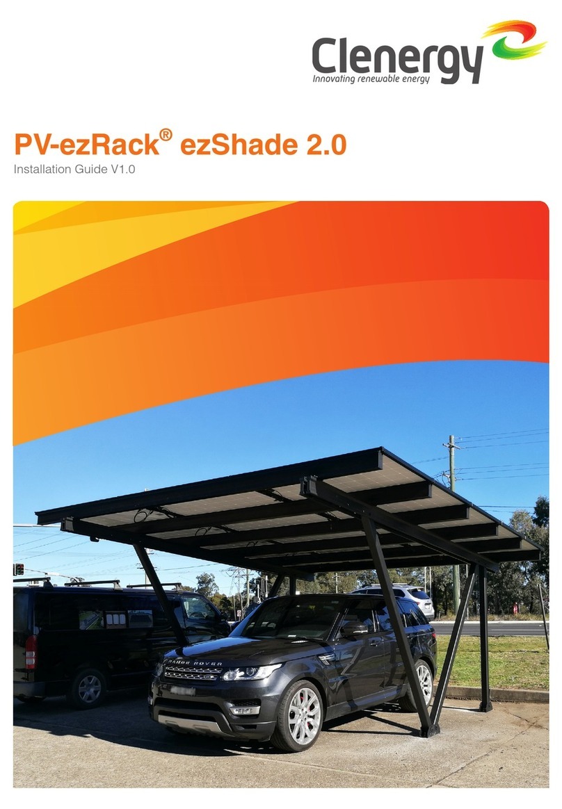
Clenergy WATERTORQUE PV-ezRack SolarTerrace II-A User manual

Clenergy Australia | 1/10 Duerdin St, Clayton VIC 3168 | T: +61 3 9239 8088 | [email protected] Page 1 of 18
PV-ezRack SolarTerrace II-A
Installation Guide
Contents
1 Introduction……………………………………………………………………..2
2 Tools & Components ………………………………………………………….3
3 System overview……………………………………………………………….4
4 Installation steps………………………………………………………………..7
5 Notices and Safety Precautions………………………………..……………14
6 Project Case…………………………………………………………..……….16
7 Service……………………………………………………………….…………17

Clenergy Australia | 1/10 Duerdin St, Clayton VIC 3168 | T: +61 3 9239 8088 | [email protected] Page 2 of 18
1. Introduction
Clenergy PV-ezRack® SolarTerrace II-A™ is a pre-assembled ground mount system suitable for
large scale commercial and utility scale installations. PV-ezRack SolarTerrace II-A has been
developed to fit any PV module. The innovative and patented SolarTerrace II-A T-Rails simplify and
improve the accuracy of the installation. SolarTerrace II-A uses high quality engineered
components, saving developers and installers time and money when delivering ground mount
projects.
Please review this instruction guide thoroughly before installing PV-ezRack SolarTerrace II-A. This
manual provides the supporting documentation for building permit applications relating to PV-
ezRack SolarTerrace II-A Universal PV Mounting System.
The PV-ezRack SolarTerrace II-A components, when installed in accordance with this guide, will be
structurally adequate and will meet the AS/NZS1170.2:2011 Amdt. 3-2012 standard. During
installation and especially when working on the ground, you will need to comply with the
appropriate occupational health and safety regulations. Please also check other regulations
relevant to your local region. Make sure that you are using the latest version of the installation
instruction guide, which you can do by contacting Clenergy by email on sales@clenergy.com.au, or
contacting your local distributor.
The installer is solely responsible for:
Complying with all applicable local or national building codes, including any that may supersede
this manual;
Ensuring that ezRack and other products are appropriate for the particular installation and the
installation environment;
Using only ezRack parts and installer-supplied parts as specified by ezRack (substitution of
parts may void the warranty and invalidate the letter of certification);
Ensuring that the ground condition are suitable;
How to recycle: according to the local relative statute.
How to disassemble: reverse installation process.
Ensure that there are no less than two professionals working on the panel installation.
Ensure the installation of the electrical equipment is performed by a professional and accredited
electrician.
Ensuring safe installation of all electrical aspects of the PV array, including providing adequate
earth bonding of the PV array and PV-ezRack® SolarTerrace II-A™ components as required in
AS/NZS 5033-2014 ADMT 2 2-2018.

Clenergy Australia | 1/10 Duerdin St, Clayton VIC 3168 | T: +61 3 9239 8088 | [email protected] Page 3 of 18
2. Tools and components
Allen key 6mm
(M8 Hexagon
Socket Screw)
Electric Drill (ST4.8
x16 self-tapping screw
& M8 Hexagon Socket
Screw)
Torque Wrench
Socket wrench with
19 mm socket
Measuring Tape
String
Marker Pen
Wrench
Electronic total
station (optional)
Hydraulic driver

Clenergy Australia | 1/10 Duerdin St, Clayton VIC 3168 | T: +61 3 9239 8088 | [email protected] Page 4 of 18
3. System overview
a.Components list
Components
ER-EC-ST
End clamp
ER-IC-ST/U18
Inter clamp U18
or ER-IC-ST
ER-R-T110
T-Rail 110
ER-RC-T
Rail clamp for T-Rail
ER-S-STIIA/S
Support(pre-assembled)
ER-PH-CP/A
Post head for C-Post
ER-CP-2400/A
C-Post
ER-PB-CP/A
post brace for C-Post
ER-SP-T110
Rail splice
ER-PB-CP/D/A
Post brace for C-Post
on double support
ER-S-STIIA/D
Double support(pre-
assembled)
ER-RC-T/A
Preassembled Rail
clamp for T-Rail 105
Note: ER-PB-CP/D/A and ER-S-STIIA/D only used on STII double support mounting systems.

Clenergy Australia | 1/10 Duerdin St, Clayton VIC 3168 | T: +61 3 9239 8088 | [email protected] Page 5 of 18
b.Overview
STII-A, Support(pre-assembled)/ Double support(pre-assembled)
STII-A, C-Post
STII-A, Post brace for C-Post/Post brace for C-Post On double support
STII-A, Post head for C-Post
T-Rail 110

Clenergy Australia | 1/10 Duerdin St, Clayton VIC 3168 | T: +61 3 9239 8088 | [email protected] Page 6 of 18
3.1 Installation in brief
Step 1: C-Post piling
Step 2: Post brace and head installation
Step 3: Pre-assembled support installation
Step 4: T-Rail 110 installation
Step 5: PV modules installation
Note: See steps below before beginning
double support installation. It is similar to
the single support systems.

Clenergy Australia | 1/10 Duerdin St, Clayton VIC 3168 | T: +61 3 9239 8088 | [email protected] Page 7 of 18
3.2 Installation Spacing
Max Frame Spacing and Footing Options of Panel Dimensions 1.7m x 1m

Clenergy Australia | 1/10 Duerdin St, Clayton VIC 3168 | T: +61 3 9239 8088 | [email protected] Page 8 of 18
Max Frame Spacing and Footing Options of Panel Dimensions 2m x 1m
Notes
*The maximum frame spacing is based on the structural capacity of the frame in the edge (perimeter
zone of array. We recommend to perform tests on site for the geotechnical capacity of the driven post.
The spacing may need to be decreased to achieve the available geotechnical capacity of the driven
post following from the test results.
**Footing option 2 recommended for 'Firm' soils with allowable end bearing capacity of 100 kPa (damp
clays, sandy clays, damp sands). Other piers sizes are possible. Contact Clenergy for site specific
conditions.
*For SolarTerrace II-A driven post installation, maximum post height above ground is 1.3m.
*For SolarTerrace II-A concrete pier installation, maximum post height above ground 1.5m.

Clenergy Australia | 1/10 Duerdin St, Clayton VIC 3168 | T: +61 3 9239 8088 | [email protected] Page 9 of 18
4. Installation instructions
1. C-Post installation
1a. Before starting, check you have
the installation tools needed.
Position the required components
close to the installation location.
Make sure that the hydraulic pile
driver equipment is suitable for your
particular installation.
Mark the line of the post array.
1b. Obtain the maximum allowed
distance between posts and the
minimum embedment length from
the relevant engineering certificate
and/or project drawing. If you don’t
have this document, please contact
the Clenergy customer service.
Mark the positions of the posts (you
can use a string and a tape
measure or a GPS) and drive the
posts into the ground. Make sure all
posts are in line and set to the
correct height according to the
drawing (you can use a sting or a
laser tool).
Note: apply zinc coating to upper
section (circled) of C-Post after
piling. The reason for that is that
ramming can damage the
galvanisation of the posts.
2. Post head installation
Install the post head and fix it with
the two M12 bolts and nuts
supplied. To avoid stainless steel
galling/seizing apply grease or
lubricant if needed.
Recommended torques:
Bolt 1: 55 Nm
Bolt 2: 23 Nm
Apply Zinc Coating to upper section
of C Post after ramming
Bolt 1
Bolt 2

Clenergy Australia | 1/10 Duerdin St, Clayton VIC 3168 | T: +61 3 9239 8088 | [email protected] Page 10 of 18
3. Post brace installation
3a.
Click the Post brace into C-Post as
shown and connect with the two
M12 bolts and nuts supplied.
Recommended torque:
55 Nm
3a. Post brace on double support
installation.
Click two post braces into C-Post as
shown and connect with the two
M12 bolts and nuts supplied.
Recommended torque:
55 Nm

Clenergy Australia | 1/10 Duerdin St, Clayton VIC 3168 | T: +61 3 9239 8088 | [email protected] Page 11 of 18
Tube of the pre-
assembled
support
4. Pre-assembled support installation
Place the (pre-assembled) support
into post head as shown.
Connect the brace to the post
using the M12 bolt and nut
supplied.
Recommended torque:
55 Nm
Post
Brace

Clenergy Australia | 1/10 Duerdin St, Clayton VIC 3168 | T: +61 3 9239 8088 | [email protected] Page 12 of 18
Double support installation
Place the double support (pre-
assembled) into post head. Connect
the tubes of the support the to the
post braces on the post using the
M12 bolt and nut supplied
Recommended torque:
55 Nm
Note: The lengths of the two tubes
are different. Make sure the shorter
one is positioned at the lover part of
the tilt as shown.
②.Connect the shorter Tube
Support to post brace.
③. Adjust the bolt position of T
head in order to prevent the hole of
the post brace can’t align to the hole
of Tube Support
④. Rotation the orientation of T
head to in order to prevent the Tube
Support can’t fit the post brace quite
well.

Clenergy Australia | 1/10 Duerdin St, Clayton VIC 3168 | T: +61 3 9239 8088 | [email protected] Page 13 of 18
Bolt 3
Bolt4
Bolt 5
Bolt 2
Bolt 2
Bolt 3
Bolt 2
Bolt 3
Bolt 2
5. System adjusting.
Please adjust Racking System
finally.
Adjust vertically: Loosen Bolt 1 and
slide along ellipse hole.
Adjust Tri-groove beam parallel:
Loosen Bolt 2 and Bolt 3, turn Post
Head slightly, move Al Tube left and
right until being parallel. Keep all of
Tri-groove beams parallel at same
level.
Note:
Make sure all of Tri-groove beams
in a line prior to installation of T-
Rails.
Check the torque value of bolt:
Bolt 1:55 Nm
Bolt 2:55 Nm
Bolt 3:40 Nm
Bolt 4:55 Nm
Bolt 5:40 Nm
Bolt 6:20 Nm
Tube Support
Bolt 1
Bolt 6
T head

Clenergy Australia | 1/10 Duerdin St, Clayton VIC 3168 | T: +61 3 9239 8088 | [email protected] Page 14 of 18
6.T-Rail Installation
6a. Slide T-Rails into Pre-
assembled rail clamp on Tri-groove
beams and use the 6mm Allen
(Hex) to fasten on another side via
Rail Clamp for T-Rail.
Recommended Torque:
M8:18Nm
Note: Rail clamps can works both
sides with no pre-assembled rail
clamp.
6b. Please determine the necessary
length of T-Rail prior to installation,
if T-Rail isn’t long enough; please
joint two rails via Rail splice as
shown before installing the T-Rail as
directed in step 6a.
Note:
Connecting Rails on Structure
system are not recommended.
6c. Now the Racking System is
completed.
Pre-assembled
Rail Clamp
Rail Clamp

Clenergy Australia | 1/10 Duerdin St, Clayton VIC 3168 | T: +61 3 9239 8088 | [email protected] Page 15 of 18
7.PV Modules Installation
7a. Fix PV panel to T-Rail 110 via
Inter Clamps and End clamps.
Maintain 20mm vertical gap and
20mm horizontal gap between the
two rows.
Use the 6mm Allen (Hex) to tighten
the bolts of the end clamps.
Tip: Use Inter Clamp U18 as the
gap location.
Recommended Torque:
M8:20Nm
7b.The installation is complete.

Clenergy Australia | 1/10 Duerdin St, Clayton VIC 3168 | T: +61 3 9239 8088 | [email protected] Page 16 of 18
5. Notices and Safety Precautions
5.1 Notices during Stainless Steel Fasteners Installation:
Improper operation may lead to deadlock of Bolts and
Screws
1.Reduce the friction coefficient:
(1)Ensure that the thread surface is clean ( no dirt or contaminant )
(2)Apply lubricant(grease or 40# engine oil) to fasteners prior tightening to avoid galling or
seizing in the threads;
2.General installation instructions:
(1)Apply force to fasteners in the direction of thread;
(2)Apply force uniformly, to maintain required torque;
(3)Professional tools and tool belts are recommended;
(4)Avoid working at high temperatures,
(5)Avoid using electric tools for final tightening;
3.Safe Torques
Please refer to safe torques defined in this guide; for the project over MW, recommend a low
speed torque when a power tool is used.
If deadlock occurs and you need to cut fasteners please make sure that there is no load on the
fasteners before you cut it. Avoid damaging the anodized or galvanized surfaces
This should be applied for every stainless steel nut and bolt assembly.
5.2 Installation Dimensions
All drawings and dimensions in this installation guide are for a generic reference. The Clenergy
STII-A is to be optimized to site specific conditions for each project and documented in a
construction drawing. As a result, major components of the Clenergy STII-A may be provided in
section sizes and lengths that vary from those shown in this guide. The installation process
detailed in this instruction guide remains the same regardless of the component size. In case you
need to do any on-site modifications or alteration of the system in the way that it would be different
from the construction drawing please provide marked up drawings/sketches for Clenergy’s review
prior modification for comment and approval.

Clenergy Australia | 1/10 Duerdin St, Clayton VIC 3168 | T: +61 3 9239 8088 | [email protected] Page 17 of 18
6. Project Case
1.
2.
3.
4.
5.

Clenergy Australia | 1/10 Duerdin St, Clayton VIC 3168 | T: +61 3 9239 8088 | [email protected] Page 18 of 18
7. Warranty
10 year limited Product Warranty, 5 year limited Finish Warranty
Clenergy co. Ltd warrants to the original purchaser (“Purchaser”) of product(s) that it
manufactures (“Product”) at the original installation site that the Product shall be free
from defects in material and workmanship for a period of ten (10) years, except for the
anodized finish, which finish shall be free from visible peeling, or cracking or chalking
under normal atmospheric conditions for a period of five (5) years, from the earlier of 1)
the date the installation of the Product is completed, or 2) 30 days after the purchase
of the Product by the original Purchaser (“Finish Warranty”).
The Finish Warranty does not apply to any foreign residue deposited on the finish. All
installations in corrosive atmospheric conditions are excluded. The Finish Warranty is
VOID if the practices specified by AAMA 609 & 610-02 – “Cleaning and Maintenance
for Architecturally Finished Aluminum” (www.aamanet.org) are not followed by
Purchaser. This Warranty does not cover damage to the Product that occurs during its
shipment, storage, or installation.
This Warranty shall be VOID if installation of the Product is not performed in
accordance with Clenergy’s written installation instructions, or if the Product has been
modified, repaired, or reworked in a manner not previously authorized by Clenergy IN
WRITING, or if the Product is installed in an environment for which it was not
designed. Clenergy shall not be liable for consequential, contingent or incidental
damages arising out of the use of the Product by Purchaser under any circumstances.
If within the specified Warranty periods the Product shall be reasonably proven to be
defective, then Clenergy shall repair or replace the defective Product, or any part
thereof, in Clenergy’s sole discretion. Such repair or replacement shall completely
satisfy and discharge all of Clenergy’s liability with respect to this limited Warranty.
Under no circumstances shall Clenergy be liable for special, indirect or consequential
damages arising out of or related to use by Purchaser of the Product.
Manufacturers of related items, such as PV modules and flashings, may provide
written warranties of their own. Clenergy’s limited Warranty covers only its Product,
and not any related items.
Watertorque Group
Address: Lot 1 Brand Highway Muchea WA 6501
Phone: (08) 9195 0351
Email: [email protected]
Table of contents
Other Clenergy Shelter manuals
Popular Shelter manuals by other brands

Dunster House
Dunster House H4-GS3X6PRG installation manual

ShelterLogic
ShelterLogic 86063EU manual

Storage Canopy
Storage Canopy FB408021P Assembly instructions

ZORO
ZORO 11C543 Operating instructions and parts manual

Kiwi Camping
Kiwi Camping Savanna 3.5 Deluxe Pitching instructions

Storage Canopy
Storage Canopy FB406021P Assembly instructions