5. System Configuration
Three SUPER 32-DT35A programming
modes are available: Local Programming
Mode (under Two-way communication),
Remote Programming Mode, and PC
Programming mode (via Super Tool).
5.1. Local Programming Mode
(under Two-way
communication)
A Local Programming Mode Slide Switch is on
the rear side of SUPER 32-DT35A. The user
can enter local programming mode by sliding
the switch to “Program” position while in two-
way communication with CMS.
This function allows user to perform
programming following the step-by-step
instructions from CMS.
Step 1. During Two-way communication with
CMS over SUPER 32-DT35A, the
CMS operator should instruct the user
to:
a) Slide the Local Programming
Mode Switch to “Program”
position and wait for SUPER 32-
DT35A to emit one beep.
b) Enter default ACCESS CODE,
8744 followed by # within 15
seconds after the beep sound.
After the beep sound, SUPER 32-
DT35A will automatically turn off it
microphone, but the speaker will keep
working for the user to listen in on
CMS operator’s instructions. If the
user needs to talk to CMS operator,
he/she should switch to using the
telephone unit.
Step 2. SUPER 32-DT35A will emit 2 short
beeps and the white backlight will start
flashing quickly, indicating it is in
Programming Mode.
Step 3. The user then proceeds to program
the system following the instructions
from the CMS live operator.
Step 4. When programming is completed, the
CMS operator should instruct the user
to enter 99 followed by # to exit
Programming mode, and slide the
Local Programming Mode Slide
Switch back to “Normal” position.
<NOTE>
The user should wait for each vocal
instrucion to be completed before
proceeding to enter a programming
command. If two-way voice and the
command key strokes overlap, it is very
likely that the command entered will not
be understood by the system, and thus be
ignored.
The first digit of Access Code must be
entered within 15 seconds otherwise
SUPER 32-DT35A will exit automatically.
Failure to enter the correct Access Code
within 2 minutes will cause SUPER 32-
DT35A to exit the Programming mode
automatically.
When in Local Programming Mode, if
there is no action for 3 minuites, SUPER
32-DT35A to exit the Programming mode
automatically.
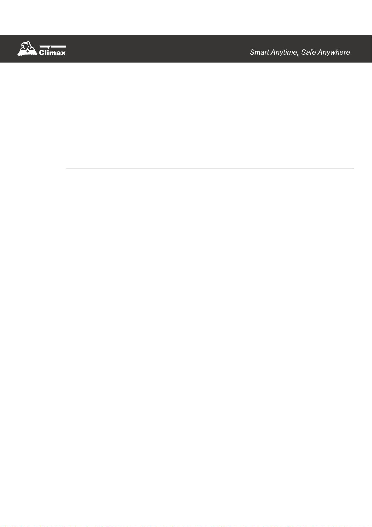
5.2. Remote Programming
Mode
To allow Remote Programming, there are two
options for SUPER 32-DT35A to answer the
incoming calls.
(1) Auto Answering by ring count
(2) Dial in twice (Ring Count disable)
The two options are set by Command #41.
Please refer to Command 41 under section
5.3 Programming your SUPER 32-DT35A.
5.2.1. Auto Answering by Ring Count
By using Command 41, you can set the
number of rings for SUPER 32-DT35A to
answer.
Step 1. Dial SUPER 32-DT35A and wait for
SUPER 32-DT35A to answer.
Step 2. Enter 8744 (default 4-digit Access
Code) followed by #, via the phone
set.
Step 3. SUPER 32-DT35A will respond with
two quick beeps to indicate it is ready
for Remote Programming.
Step 4. You are now in Programming Mode.
Proceed to program by referring to the
Command in section 5.3
Programming Your SUPER 32-
DT35A.