Climax VCP-LTE User manual

VCP-LTE
Voice Call Point
Installation Guide
Nov 19, 2021

Table of Contents
1. INTRODUCTION ________________________________________________________________________ 1
2. APPLICATION OVERVIEW_______________________________________________________________ 2
2.1. PARTS IDENTIFICATION ___________________________________________________________ 2
2.2. THE POWER SUPPLY _____________________________________________________________ 3
3. GETTING STARTED _____________________________________________________________________ 4
3.1. INSERT A SIM CARD _____________________________________________________________ 4
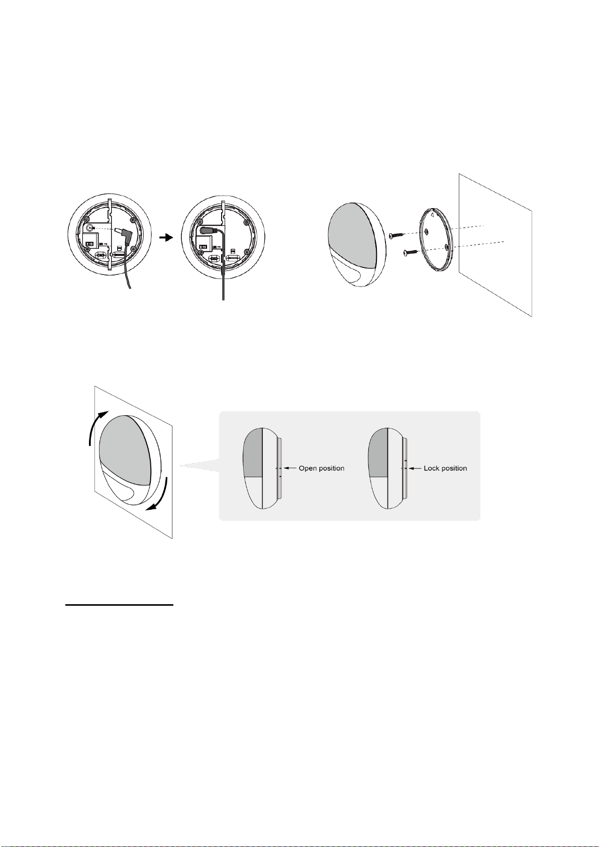
3.2. MOUNTING ____________________________________________________________________ 4
3.3. HARDWARE INSTALLATION (FOR PC PROGRAMMING TOOL) ________________________________ 6
3.4. SOFTWARE INSTALLATION (FOR PC PROGRAMMING TOOL) ________________________________ 8
3.4.1 Installing USB Driver________________________________________________________________ 8
3.4.2 Installing PC Programming Tool _____________________________________________________ 8
4. PROGRAMMING VCP-LTE _______________________________________________________________ 9
4.1 PC PROGRAMMING TOOL (INSTALLERS ONLY)__________________________________________ 9
4.1.1 Profile __________________________________________________________________________ 11
4.1.2 SMS Program ___________________________________________________________________ 12
4.1.3 APN ____________________________________________________________________________ 13
4.1.4 Report __________________________________________________________________________ 14
4.1.5 Setting__________________________________________________________________________ 19
4.1.6 Device __________________________________________________________________________ 23
4.1.7 Miscellaneous___________________________________________________________________ 24
4.1.8 Firmware________________________________________________________________________ 25
4.2 SMS REMOTE PROGRAMMING_____________________________________________________ 26
5. LOCAL RF DEVICE MANAGEMENT _____________________________________________________ 27
6. OPERATION ___________________________________________________________________________ 28
6.1 ANSWERING INCOMING CALLS _____________________________________________________ 28
6.2 ALARM ACTIVATION_____________________________________________________________ 28
6.2.1 Callback Mode __________________________________________________________________ 29
6.2.2 Speech Reporting Method________________________________________________________ 30
7. APPENDIX_____________________________________________________________________________ 32
7.1 SMS REMOTE PROGRAMMING COMMANDS TABLE ______________________________________ 32
7.2 CONTACT ID COMMUNICATIONS PROTOCOL AND FORMAT ________________________________ 33

1
1. Introduction
VCP-LTE is an AC-powered Emergency Voice Call Point, having one button that can be
used to activate alarm and report events via Speech, SMS and IP (Mobile Network)
protocols to directly communicate with the monitoring center.
The medical alarm system can integrate with multiple devices/sensors: Wrist Transmitter,
Emergency Pendant, Fall Sensor, PIR Motion Sensor, Panic Button, Smoke Detector,
Water Leakage Sensor, and CO Sensors, etc.
VCP-LTE can be programmed by using programming software via Micro USB Jack
connection, providing intuitive graphical interface for installers to program the device
easily from a computer.

2
2. Application Overview
2.1. Parts Identification
1. ALARM Button
2. LED Indicator (Red)
- Flashes once every 2 seconds: Low Battery.
- Flashes once every 5 seconds: GSM fault.
3. LED Indicator (Green)
- Light on: AC Power on.
- Flashes once every 5 seconds: AC Fail.
4. Speaker
5. Microphone
6. DC Jack
- For connecting to 9V 1A DC adaptor.
7. Battery Switch
8. Micro USB Jack
9. NANO SIM Card Slot
10.Mounting Holes
11.Triangle Mark
- The triangle mark should point straight up when the bracket is fixed on the wall.

3
2.2. The Power Supply
The Voice Call Point can be powered by either AC power or backup battery.
AC Power
A DC 9V 1A SPS power adapter is provided for AC power connection.
- When AC power is connected, the Green LED will turn steady on to indicate AC
connection.
- When AC power is disconnected, the Green LED will flash once every 5 seconds to
indicate AC failure, the Voice Call Point will make AC fail report.
Backup Battery
In addition to the AC power adapter, a rechargeable battery is installed inside VCP-LTE
to serve as a backup in case of a power failure.
-During normal operation, the AC power adapter is used to supply power to VCP-LTE
and at the same time recharge the battery. It takes approximately 72 hours to fully
charge the battery.
-If the battery switch is set as OFF, the battery will not be charged when AC power is
connected and nor will it serve as a backup power source when AC power is missing.
You need to switch the battery to ON for it to be charged when AC power is connected
and serve as a backup power source when AC power is missing.
Low Battery Detection
The Voice Call Point can detect the battery voltage. When the battery voltage is low, the
Voice Call Point will make Low Battery report.
If the battery is extremely low, the Voice Call Point will stop all function. It will not report
upon alarm activation and will emit 4 beeps as an alert.

4
3. Getting Started
3.1. Insert a SIM card
VCP-LTE features built-in Cellular network communication facility to report to the
Monitoring Station.
To Insert SIM card:
It is recommended to disable the SIM card PIN code before inserting into the
VCP-LTE.
The SIM card base is located on the back side of the unit.
Push to the furthest extend, then press on the edge of the SIM card firmly to secure
it.
SIM Card will delete its SMS messages whenever the VCP-LTE is powered on.
<WARNING>
Only a Nano SIM card can fit it the SIM card slot. If you don't have the right SIM size,
please contact your service provider for a replacement SIM card.
Do not insert a SIM card with a SIM card adapter or it will cause damage to the SIM
card and its holder.
3.2. Mounting
The VCP-LTE can be mounted on the wall or deployed on a flat surface.
Wall Mounting
Ensure VCP-LTE is fitted at approximately chest height where the button can be easily
accessed and operated.
1. Break through the 2 knockouts on the Wall Mounting Bracket.

5
2. Use the 2 holes as a template to mark off the holes’ positions. Make sure that the
triangle symbol on the bracket points straight up.
3. Drill 2 holes and screw the bracket onto the wall.
4. Connect a DC 9V 1ASPS power adapter to DC jack of VCP-LTE and keep the cable
well-placed.
5. Fit VCP-LTE onto the mounting bracket. Make sure the imprinted mark on VCP-LTE
B is aligned with the upper mark on the bracket.
6. Rotate VCP-LTE clockwise to the lock position.
Surface Placement
The VCP-LTE can be deployed on a flat surface without being installed at a fixed
location.
1. Clean the back of VCP-LTE with degreaser.
2. Connect a DC 9V 1A SPS power adapter to DC jack and keep the cable well-placed
to the right or left. (Picture 1)
3. Remove the protective cover of Anti-Slip pad and apply to the back of VCP-LTE.
(Picture 2)
4. Place VCP-LTE at desired location. (Picture 3)
Picture 1
Picture 2
Picture 3

6
3.3. Hardware Installation (For PC Programming Tool)
To use PC Programming Tool for programming VCP-LTE, follow the hardware
installation steps below:
Step 1. Insert the device/cradle end of the Programming Micro-USB Cable into the
Micro-USB jack as shown in the picture:
Step 3. Insert the programming end of the Programming Micro-USB Cable into a
computer USB port as shown in the picture below:

7
<WARNING>
If programming cable is not provided, please contact your supplier. DO NOT
attempt to connect VCP-LTE to computer with a regular Micro-USB cable.
Programming
Micro-USB Cable
Regular Micro-USB
Cable

8
3.4. Software Installation (For PC Programming Tool)
3.4.1 Installing USB Driver
VCP-LTE can be programmed via USB port connection of a computer using the PC
Programming Tool software (using the Programming Cable).
If the computer cannot recognize the USB connection, please try installing the USB
driver as instructed below.
Step 1. Make sure VCP-LTE and the computer is connected properly (please refer to
3.3. Hardware Installation)
Step 2. Please go to http://www.ftdichip.com/Drivers/VCP.htm. Scroll down the
webpage and select the driver file according to your operation system, download and
install the driver.
3.4.2 Installing PC Programming Tool
PC Programming Tool for VCP-LTE is a portable application and requires no installation.
After installing the USB driver, simply unzip the file to a desired folder and execute the
“Mobile_Tool_VCP_LTE_Panel.exe” file.

9
4.Programming VCP-LTE
VCP-LTE can be programmed by using a PC Programming Tool.
4.1 PC Programming Tool (Installers Only)
For system setting programming with PC Programming Tool software via USB port,
follow instruction below.
Step 1. Execute the programming tool:
The following configuration screen will be opened.
Step 2. Select the following settings in the top section of the configuration screen and
click “Open.”
Port: Select the COM port generated for VCP-LTE after installing the USB
Driver (the USB port connected to VCP-LTE).

10
Baud rate: 115200
Data: 8
Parity: None
Stop: 1
FlowCtrl: None
Step 3. Read Configuration
To start configuring VCP-LTE settings, click on “Open”. A Read configuration success
message will pop up, click “OK” to proceed:
The current VCP-LTE setting will be displayed. Click on different tabs to see and edit
VCP-LTE functions.

11
4.1.1 Profile
The Profile function allows you to create and edit different setting profiles which can be
easily accessed in the future for quick programming.
Current Setting
After reading the configuration of VCP-LTE, the Profile scroll down bar will now display
“Current Setting” indicating PC Programming Tool is now displaying the current
VCP-LTE configurations. Selecting different tabs will show the current values of each
setting.
If you select a different profile from the drop down menu, the “Current Setting” profile
will disappear to indicate the PC Programming Tool is no longer displaying VCP-LTE’s
current configuration. To access Current Setting again, click on “Read”.
Default
When “Default” is selected, the PC Programming Tool will display default configurations
of VCP-LTE, you can use this profile to return VCP-LTE to its default setting.
New Profile
To create a new profile, click on “New Profile”. A pop-up window will prompt you to enter
a profile name:
After entering a profile name, the profile scroll down bar will show the new profile name:
After editing the settings, click “Save Profile”to save the profile settings. A pop-up
window will indicate the profile has saved. You can use this profile in the future to apply
the same setting to other VCP-LTE.
Apply profile
If you wish to apply all the configuration of a profile into VCP-LTE, go to each individual
page and click on all the “Write”buttons to make sure all settings are programmed into

12
VCP-LTE.
Profile Manager
Click on “Profile Manager” to manage the profiles:
Delete Profile
Select a profile and click on “Delete Profile”. A pop-up window will ask you to confirm
the selection:
Select “Yes” to delete the profile, or “No” to return to the previous page.
4.1.2 SMS Program
This tab allows the user to program SMS Keyword (15 characters max.) and Access
Code 1 (4-8 digits) which are used for SMS Programming feature. Enter the information
and click “Write” to complete programming. Please note that SMS Keyword is
case-sensitive. For detail information, please refer to 4.2. SMS Remote Programming.
SMS Keyword: PROG (default)
Access Code: 1111 (default)

13
4.1.3 APN
The APN setting must be completed for VCP-LTE to report events via cellular network.
Click “APN” to set APN Name, APN User and APN Password and click “Write” to
confirm.
APN Name: The name of an access point for GPRS. Please ask your SIM card
service provider for your APN.
APN User: Offered by your SIM card service provider. Please ask your service
provider for your GPRS username. If no username is required, you may skip this
step.
APN Password: Offered by your SIM card service provider. Please ask your
service provider for your GPRS password. If no password is required, you may skip
this step.

14
4.1.4 Report
The “Report”tab allows the user to configure report settings.
VCP-LTE reports over 3 media: Speech channel, Cellular Network, and SMS
message.
5 Report Indexes are available for setting:
4 programmable settings are available per Report Index:
1. Report Destination
Enter a report destination. The format of the report destination will depend on the
Reporting Format (Type). Please see Report Destinations below.
If there are no report destinations programmed, VCP-LTE will not report after Guard
Time expires.
2. Event Filter
Select an event filter. The event filter determines which events are reported to the
selected Report Destination.
3. Reporting Format (Type)
Select a reporting format. The reporting format determines how the events are
reported to the Report Destination.
4. (Reporting) Groups
Assign the Report Index to a Reporting Group. The Reporting Group determines the
sequence of reporting.
Click “Write” to apply the settings to VCP-LTE.
Report Destinations
After Report Format is determined, enter the Report Destinations according to the
designated Report Format:
IP Report Format: AccountNumber@server:port
IP Reporting: When activated, VCP-LTE will send event code and location
information (if available) via mobile network.
AccountNumber: Enter 4 to 23 alphanumeric account number assigned by CMS.

15
Server: Enter either the IP address or the domain name of receiver.
Port: Separate from Server with a colon “:”, then enter the port number
For XML Report Format, you can also enter
http://AccountNumber@server url or
https://AccountNumber@server url
AccountNumber: Enter 4 to 23 alphanumeric account number assigned by CMS.
Server URL: Enter the Server URL of receiver.
Example : http://111111@developer.climaxrd.com/soap/test
https://111111@developer.climaxrd.com/soap/test
Speech reporting and SMS Text Report Format: PhoneNumber
Example: 0912345678
Speech Reporting: When activated, VCP-LTE will dial to the telephone number
and open two-way voice communication directly.
SMS Text Reporting: When activated, VCP-LTE sends a SMS text message to the
recipient. The message contains event information.
If two-way communication is required after an IP or SMS report, please program a
separate Speech Report.Alternatively, the user can also utilize Callback operation.
Event Filter
This parameter determines which events are reported to the selected Report
Destination.
3 options: “All”, “Emergency”and “Status”. When an event is triggered, it will be
reported to the reporting destination according to the setting. If set to All, the panel will
report all events regardless of event type.
For example:
VCP-LTE being low on battery is a “status” event. If report index 3 and 5 are set as
“status” and index 4 as “all” in event filters, this status event will be reported to
destinations 3, 4, and 5.
For more information, refer to 7. Appendix for event code types.
Reporting Format (Type)
The available reporting format includes:
Speech: VCP-LTE reports over the Speech channel to allow the user to talk directly
to the call recipient.
SIA_CID over IP:VCP-LTE reports digital CID event codes over mobile network
TCP Protocol in SIA format.

16
SIA2_CID over IP: VCP-LTE reports digital CID event codes over mobile network
TCP Protocol in SIA2 format.
SIA over IP:VCP-LTE reports digital SIA event codes over mobile network TCP
Protocol.
SIA2 over IP: VCP-LTE reports digital SIA2 event codes over mobile network TCP
Protocol.
SIA_CID over UDP: VCP-LTE reports digital CID event codes over mobile network
UDP Protocol in SIA format.
SIA2_CID over UDP: VCP-LTE reports digital CID event codes over mobile
network UDP Protocol in SIA2 format.
SIA over UDP: VCP-LTE reports digital SIA event codes over mobile network UDP
Protocol.
SIA2 over UDP: VCP-LTE reports digital SIA2 event codes over mobile network
UDP Protocol.
XML: XML reporting in Avant Guard XML protocol.
SMS CID: VCP-LTE sends a SMS text message containing event code.
SMS TEXT: VCP-LTE sends a SMS text message containing event information.
Group
The Reporting Group determines the sequence of reporting.
One Report Index can only be assigned to one Group.
Reporting within a Group:
If there are multiple Report Indexes programmed within a Group:
VCP-LTE will report according to the numeric order (e.g. 1 > 2 > 3, etc.) of the
Report Index in a Group. Report will stop when one report is successful and
VCP-LTE will regard reporting to this Group successful.
For example, if Report Index 1 and 4 is assigned to Group 1, VCP-LTE will stop
reporting if reporting to Index 1 is successful. If reporting to Index 1 failed, VCP-LTE
will carry on reporting to Index 4.
VCP-LTE will try the report destinations within a group for up to 4 times in total. If all
report destinations failed after the total of 4 tries, VCP-LTE will regard reporting to
this Group unsuccessful.
From the example above, suppose all report failed, the report sequence would be:
1 > 4 > 1 > 4
Reporting Cycle
If multiple groups are assigned to the same event type (emergency or status),

17
VCP-LTE will report according the group numeric order from the first programmed
Group to the last programmed group. This report sequence is one reporting cycle.
Reporting cycle is regarded as successful if any Group is successful, but VCP-LTE
will terminate reporting only after completing the reporting cycle (going from the first
programmed group to the last programmed group).
Reporting behavior depends on the event type:
Emergency Events:
- When reporting to the first group is successful, Reporting is regarded as
successful. VCP-LTE will still report to the next group until all groups
have been tried to complete the reporting cycle.
For example, Groups 1 and 3 are assigned to Emergency Events:
If Group 1 is successful, VCP-LTE will still report to Group 3.
If reporting to Group 3 is successful, VCP-LTE will terminate reporting.
If reporting to Group 3 is unsuccessful (going through all the Report Index
within the group for 4 tries), VCP-LTE will also terminate reporting.
- When reporting to the first group failed (going through all the Report
Index within the group for 4 tries), VCP-LTE will start reporting to the next
group. When reporting to the second group succeeds, reporting is
regarded as successful. If no other group is programmed, VCP-LTE will
stop reporting. If there are more groups programmed, VCP-LTE will
continue reporting until all groups have been tried to complete the
reporting cycle.
- If reporting to all the programmed groups failed in a reporting cycle,
VCP-LTE will wait for 5 minutes. After 5 minutes, VCP-LTE will retry as it
starts another reporting cycle.
- For Emergency event, VCP-LTE will repeat a reporting cycle for up to 3
times, with a 5-minute pause between each cycle, and then terminate
reporting.
Example 1, if Groups 1 and 3 are programmed for “Emergency”reports, and
assuming NO successful report:
Group 1 > Group 3 > Wait 5 minutes > Group 1 > Group 3 > Wait 5 minutes >
Group 1 > Group 3 > Stops reporting.
Example 2, if Groups 1 and 3 are programmed for “Emergency”reports, and
assuming NO successful report until Group 1 is successful after several
retries:
Group 1 > Group 3 > Wait 5 minutes > Group 1 > Group 3 > Wait 5 minutes >
Group 1 (Success!) > Group 3 > Stops reporting whether Group 3
succeeded or not.
Status Events:
VCP-LTE will only go through one reporting cycle for Status reports.

18
For example, if Groups 1 and 3 are programmed for “Status”reports:
Group 1 > Group 3 > Stops reporting whether Groups 1 and 3 succeeded or not
SMS Report text format
Below are the SMS Text messages sent to user according to the condition of the
Base.
SMS text table:
VCP-LTE Condition
SMS Text format
Low battery status
VCP Low Battery
Battery voltage restored
VCP Battery Restored
Wakes up time
VCP Periodic Test
AC Power disconnected
VCP Power Failure
AC Power connected
VCP Power Restored
Table of contents
Other Climax Personal Care Product manuals

Climax
Climax SUPER 32-DT35A User manual

Climax
Climax Mobile Mates R8 Slim Assembly instructions

Climax
Climax Mobile Pro Series Assembly instructions

Climax
Climax Vesta Series User manual

Climax
Climax WTRVS User manual

Climax
Climax Vesta Series Operating instructions

Climax
Climax Vesta Series User manual

Climax
Climax Mobile Lite-R8 Slim Assembly instructions