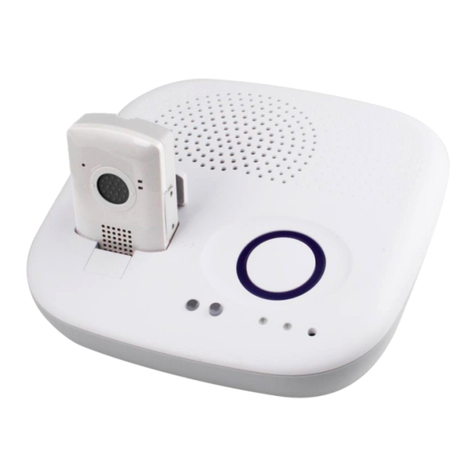
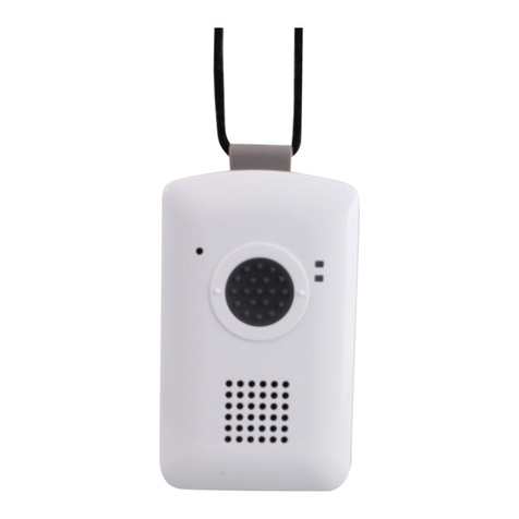
Climax Vesta Series Operating instructions

26-Feb-2013

Table of Contents
1. INTRODUCTION .................................................................................................................... 1
1.1. MOBILE PERS SERIES ........................................................................................................... 1
1.2. WHAT’S IN THE BOX .............................................................................................................. 2
1.3. OPTIONAL SOFTWARE AND ACCESSORIES .......................................................................... 3
2. SYSTEM OVERVIEW ............................................................................................................ 4
2.1. IDENTIFYING THE PARTS ....................................................................................................... 4
2.1.1. Base Station .................................................................................................................. 4
2.1.2. Mobile Unit ..................................................................................................................... 8
2.1.3. Usage Advice .............................................................................................................. 10
2.2. POWER SUPPLY .................................................................................................................. 13
2.2.1. Base Station ................................................................................................................ 13
2.2.2. Mobile Unit ................................................................................................................... 13
2.2.3. Battery Life .................................................................................................................. 14
3. GETTING STARTED – INSTALLING MOBILE PERS ...................................................... 15
3.1. SETTING UP THE BASE STATION ......................................................................................... 15
3.2. SETTING UP THE MOBILE UNIT ........................................................................................... 16
4. PROGRAMMING MOBILE PERS....................................................................................... 17
4.1. INSTALLING USB DRIVER ................................................................................................... 17
4.2. PC PROGRAMMING TOOL ................................................................................................... 24
4.3. SMS REMOTE PROGRAMMING ........................................................................................... 50
5. DEVICE MANAGEMENT ..................................................................................................... 56
5.1. LEARNING IN PENDANT #1, PENDANT #2 AND OTHER DEVICES ....................................... 56
5.2. REMOVING PENDANT #1, PENDANT #2 AND OTHER DEVICES .......................................... 57
6. OPERATION ......................................................................................................................... 59
6.1. MOBILE UNIT ....................................................................................................................... 59
6.1.1. Normal Mode ............................................................................................................... 59
6.1.1.1. Answering Incoming Calls ........................................................................................... 59
6.1.1.2. Battery Checkup ............................................................................................................. 60
6.1.2. Alarm Activation ......................................................................................................... 60
6.1.3. Voice Prompts ............................................................................................................ 64
6.1.4. Rebooting the Mobile Unit and Factory Reset ................................................... 64
6.2. BASE STATION .................................................................................................................... 66
6.2.1. Idle Mode ...................................................................................................................... 66

6.2.1.1. Answering Incoming Calls ........................................................................................... 66

6.2.1.2. Non-Emergency Calls ................................................................................................... 67
6.2.1.3. AC Power Checkup ........................................................................................................ 67
6.2.1.4. Base Station Low on Battery ....................................................................................... 68
6.2.1.5. Base Station’s Battery Disconnected ....................................................................... 68
6.2.1.6. Devices Low on Battery ................................................................................................ 68
6.2.1.7. Automatic Check-In Reports ....................................................................................... 69
6.2.1.8. Inactivity Timer ............................................................................................................... 69
6.2.2. Alarm Activation ......................................................................................................... 70
6.2.3. Arming/Disarming the System ............................................................................... 75
6.2.4. Voice Prompts ............................................................................................................ 76
6.2.5. Walk Test (Range Test) ............................................................................................. 77
6.2.6. Factory Reset .............................................................................................................. 77
7. APPENDIX ............................................................................................................................ 79
7.1. CONTACT ID EVENT CODES ............................................................................................... 79
7.2. SCANCOM EVENT CODES ................................................................................................... 80
7.3. TUNSTALL TTNEW EVENT CODES .................................................................................... 82
7.4. CLIMAX CPC DIALECT EVENT CODES ............................................................................... 83
7.5. FRANKLIN EVENT CODES ................................................................................................... 84

1
1. Introduction
1.1. Mobile Pers Series
Mobile Pers is a portable and richly featured Cellular Medical Alarm System
with GSM or 3G network that protects the user wherever he goes. Patented in
the United States and Europe, this system includes a Base Station and a
Mobile Unit that works both inside and outside home. The Mobile Unit is a
complete Medical Alarm System in itself, using multiple built-in reporting
formats to directly communicate with the Central Monitoring Station (CMS).
Mobile Pers enables the CMS to send assistance to its user efficiently in the
event of an emergency. This system further provides security functions to
protect the safety of your family members.

2
1.2. What’s in the Box
Your Mobile Pers sample package includes the following items:
For whom Item
For the Mobile Pers user Base Station
Mobile Unit
Protective jelly case with a lanyard (for the Mobile Unit)
AC power adapter (CT-1)
Installation Kits* for the
installer
USB cable
CD-ROM containing
- Mobile Pers Installation and Operation Guide
- USB Driver for Mobile Pers
- PC Programming Tool
-
*The Installation Kits package can be purchased alone. It does not include the
Base Station, the Mobile Unit, the protective jelly case and the AC power
adapter.

3
1.3. Optional Software and Accessories
You can purchase the following software or accessories separately from the
Mobile Pers package:
Item
Usage
SMS iWizard
SMS iWizard is designed to facilitate SMS remote programming
via a PC. You can use this tool to conveniently configure Mobile
Pers on your PC without sending SMS text messages from a
mobile phone.
Mobile Updater (CT-2)
CD-ROM containing
- CT-2 User Guide
- Mobile Unit Firmware Update Tool
- USB Driver for CT-2
Travel Charger (CT-1) To charge the Mobile Unit when the user is traveling

4
2. System Overview
2.1. Identifying the Parts
2.1.1. Base Station
Top View Back View
S
Side View

5
Base Station Definitions
Button/LED/Component
Behavior Function/Indication
1 Red Help Button Pressed in idle/normal mode
To summon emergency help
Pressed once in learning
mode
To select Pendant #2
Pressed for 3 seconds in
learning mode
To delete a selected pendant
2 Red Backlight Dimly lit Idle/normal mode
Blinking 1. Guard time
2. Pauses during retries of
alarm reporting
Brightly illuminating 1. Busy with alarm
reporting
2. After an alarm report
receives a callback and
until the call is hung up
3 Green Reset Button Pressed in idle/normal mode
1. To reset the inactivity
timer
2. For the Base Station to
report all the fault
problems it is
experiencing via voice
prompts
Pressed once before the
Base Station dials out for
alarm reporting
To cancel the alarm reporting
Pressed once during or at
the end of a two-way
communication
To terminate the two-way
communication
Pressed for 3 seconds in
idle/normal mode
To make a non-emergency
call (whether or not the
yellow button is programmed
as an away/home button)
Pressed for 10 seconds in
idle/normal mode
To reset the Mobile Unit
Pressed once in learning
mode
To select Pendant #1
4 Yellow Away/Home
Button
(Non-Emergency Call
Button)
Pressed once when serving
as an away/home button
To toggle on/off the inactivity
timer
Pressed once when serving
as a security button
To arm the system
Pressed once when serving
as a non-emergency button
To make a non-emergency
call
Pressed for 3 seconds To enter learning mode
Pressed once in learning
mode
To exit learning mode
5 Blue Backlight Steady on The inactivity timer is on.
Off The inactivity timer is off.

6
Button/LED/Component
Behavior Function/Indication
5 Blue Backlight
Blinking
The Base Station is in
learning mode.
6 Orange Backlight
Steady on 1. After a non-emergency
call is dialed out and until
the call is hung up
2. Busy with status
reporting
Off 1. Idle mode
2. Pauses during retries of
status reporting
Blinking The Base Station has a line
fault problem.
When the inactivity timer is on and one of the conditions
under the orange backlight takes place, the yellow
away/home button’s backlight will turn purple.
7 Green LED (Volume
Switch)
Steady on AC power is on.
Blinking twice every second AC power fails.
Blinking every 2 seconds The Base Station or a device
is lower on battery.
Pressed once To increase the speaker
volume
8 Yellow LED (Volume
Switch)
Blinking every second The Mobile Unit is being
charged.
Steady on
The Mobile Unit is fully
charged.
Off The Mobile Unit is not
inserted in the Base Station’s
charging base.
Blinking rapidly (4 times per
second)
The Mobile Unit cannot
charge because of its poor
contact with the Base
Station’s charging base.
Pressed once To lower the speaker volume
9 Microphone
10 Charging Base To charge the Mobile Unit
11 Speaker
12 Battery Switch On/off
13 DC Jack
Connects to a DC 12V 2A switching power adapter.
14 Phone Jack Marked
Connects to a phone line from the wall (on MP-2 and MP-5
only).
15 Phone Jack Marked
Connects to a telephone unit (on MP-2 and MP-5 only).

7
16 Ethernet Port (On MP-3 and MP-5 only)
17 USB Port

8
2.1.2. Mobile Unit
Front View Side View Bottom View
Mobile Unit Definitions
Button/LED/Component
Behavior Function/Indication
1 Red Help Button
Pressed once when the
Mobile Unit is ringing
To pick up the call
Pressed for 5 seconds
during a call
To terminate the call
Pressed once (when off the
Base Station and in normal
mode)
To trigger a panic
report/summon emergency
help
Pressed for 15 seconds in
any mode
To enter reset mode: All the
Mobile Unit’s LEDs will be on
for 1 second and go off. The
Mobile Unit will enter reset
mode for 10 minutes. Now
you can:
1. Press the red help button
once to reboot the
Mobile Unit. Or
2. Give the red help button
2 quick presses to
restore the Mobile Unit to
factory settings (the 2
presses must be
completed in 1 second).

9
Button/LED/Component Behavior Function/Indication
2 LED 1A (Green)
Blinking every 2 seconds The Mobile Unit is being
charged.
Steady on The Mobile Unit is fully
charged.
Blinking every 5 seconds The Mobile Unit is in normal
operation.
2 LED 1B (Orange)
Blinking every 3 seconds The Mobile Unit is low on
battery.
3 LED 2A (Red) Blinking every second Guard time/retrying
reporting/pauses during
retries
Steady on The Mobile Unit is reporting.
3 LED 2B (Orange) Blinking quickly (every 0.4
second)
To signal a GSM fault
4 Microphone
5 Speaker
6 Micro SIM Card Slot
7 Charging Port (Docking
Connector)

10
2.1.3. Usage Advice
Please follow the usage advice below to avoid operational glitches.
Inserting the Mobile Unit: When you insert the Mobile Unit into the
Base Station, please press your hand softly on the speaker area of the
Base Station to keep the Base Station staying stable on the table.

11
Taking out the Mobile Unit: When you take out the Mobile Unit from the
Base Station’s charging base, please press your hand softly on the
speaker area of the Base Station to keep the Base Station staying firm
and stable on the table. Push the Mobile Unit forward as shown below
before taking it out.
Then you can gently pull the Mobile Unit out of the charging case.

12
Using the Mobile Unit: When you press the Mobile Unit’s red button to
summon help, please make sure that your hand does not cover the area
with white dots. Please hold your Mobile Unit as shown in the photo
below. The Mobile Unit’s operating temperature ranges from 0°C to 45°C.
Mobile Unit Case: A protective jelly case for the Mobile Unit is provided
in your Mobile Pers package. Please remember to take the Mobile Unit
out of the jelly case, fully charge it, and return it to the protective case
before usage. Put your Mobile Unit in this case for its protection and for
your convenience of using and carrying around the device.

13
2.2. Power Supply
2.2.1. Base Station
Plug the AC power adapter into the Base Station’s DC jack and connect to
the mains power. Make sure that you use an adapter with the appropriate
AC voltage rating to prevent component damage. An AC-DC 12V/2A
switching power adapter is generally used to power the standard version
of the Base Station.
In addition to the AC power adapter, a rechargeable battery is installed
inside the Base Station to serve as a backup in case of a power failure.
During normal operation, the AC power adapter is used to supply power to
the Base Station and at the same time recharge the battery. It takes
approximately 72 hours to fully charge the battery.
If the battery switch is set as OFF, the battery will not be charged when
AC power is connected and nor will it serve as a backup power source
when AC power is missing. You need to switch the battery to ON for it to
be charged when AC power is connected and serve as a backup power
source when AC power is missing.
When the Base Station is experiencing an AC power failure or low on
battery, it will not charge the Mobile Unit.
2.2.2. Mobile Unit
Charge the Mobile Unit battery by inserting the Mobile Unit in the charging
base on the Base Station. In addition, a travel charger (to be purchased
separately from the Mobile Pers package) can be used to charge your
Mobile Unit when you are away from home.
When the Mobile Unit is being charged, LED 1A (green) blinks every 2
seconds. When the Mobile Unit is fully charged, LED 1A (green) is steady
on.
The Mobile Unit needs to charge for 4 consecutive hours for its low battery
status to return to normal battery status. Please use the Mobile Unit after
LED 1A (green) and the Base Station’s yellow LED are both steady on to
indicate the Mobile Unit has fully charged.
When the Mobile Unit is low on battery, LED 1B (orange) blinks every 3
seconds.
The Mobile Unit makes a low battery report to the CMS when it is running
low on battery.
The Mobile Unit makes a battery restored report to the CMS when its
battery is fully recharged.
When the Mobile Unit is low on battery, it plays the voice prompt: “Mobile
Unit battery is low. Please charge it.”

14
2.2.3. Battery Life
Comparing the battery life (1100mAh battery) of different models:
433AM 868FM
Mobile Unit Base Station Mobile Unit Base Station
MP-1 Classic 46 rs 24 rs 62 rs 18 rs
MP-2 Classic 53 rs 21 rs 69 rs 16 rs
MP-3 Classic 46 rs 24 rs 62 rs 18 rs
MP-5 Classic 53 rs 21 rs 69 rs 16 rs

15
3. Getting Started – Installing Mobile Pers
3.1. Setting up the Base Station
Step 1. Choose a suitable location for the Base Station. The Base Station
requires the mains power and PSTN/Ethernet connections (PSTN for
MP-2 and MP-5; Ethernet for MP-3 and MP-5) and should be easily
accessible. It should not be placed in a damp location such as a
bathroom or close to a heat source like a microwave oven, which
could reduce signal strength.
Step 2. Plug the USB cable into the Base Station’s USB port and connect to a
PC for Mobile Pers programming.
Step 3. Connect a PSTN line and a telephone line to the Base Station for
Mobile Pers to operate via PSTN (MP-2 and MP-5 only).
Step 4. Plug an IP cable into the Base Station’s Ethernet port and connect to
an Ethernet network for Mobile Pers to operate via Ethernet (MP-3
and MP-5 only).
Step 5. Plug the AC power adaptor into the Base Station’s DC jack and
connect to the mains power. The Base Station will emit two beeps to
indicate the system is now ready for further operation.

16
3.2. Setting up the Mobile Unit
Step 1. Please take the Mobile Unit out of the protective jelly case and use
tweezers to pull open the rubber cap covering the SIM card slot.
Step 2. Hold the Mobile Unit with its front side facing you. Insert a micro SIM
card into the SIM card slot on the side of the Mobile Unit with the chip
side of the SIM card facing you. Please make sure that the micro SIM
card PIN code is deactivated and all SMS messages removed before
insertion.
Step 3. Insert the Mobile Unit into the charging base on the Base Station to get
its battery charged.
<
<N
NO
OT
TE
E>
>
The Mobile Unit must be inserted on the Base Station when you configure
the Base Station and the Mobile Unit via USB PC programming or SMS
remote programming (SMS programming is optional).

17
4. Programming Mobile Pers
4.1. Installing USB Driver
Please first install the USB Driver provided in your CD-ROM on your PC.
<
<N
NO
OT
TE
E>
>
It is recommended that you use Windows XP or Windows 7 operating
systems.
Step 1. Plug the USB cable into the Base Station’s USB port and connect to a
PC. Make sure that the Mobile Unit is inserted in the charging base
on the Base Station.
Step 2. Insert the supplied CD-ROM into your CD-ROM drive and find the
“USB Driver” folder (you may copy and paste the folder to your
desktop for later use). Click the “Start” button at the bottom left-hand
corner of the screen and then click “My Computer” and “Manage.”
Other manuals for Vesta Series
7
This manual suits for next models
2
Table of contents
Other Climax Personal Care Product manuals

Climax
Climax Mobile Pro Series Assembly instructions

Climax
Climax Mobile Lite-R8 Slim Assembly instructions

Climax
Climax WTRVS User manual

Climax
Climax SUPER 32-DT35A User manual

Climax
Climax Vesta Series User manual

Climax
Climax VCP-LTE User manual

Climax
Climax Mobile Mates R8 Slim Assembly instructions

Climax
Climax Vesta Series User manual