CMP DEL AOP 50 User manual

4-2305-01 Rev.E
CMP.COM/DEL
DEL AOP 50
INSTALLATION INSTRUCTIONS
& PRODUCT MANUAL

READ AND FOLLOW ALL INSTRUCTIONS.
• Read this manual completely before attempting installation. Failure
to install in accordance with the installation instructions could void
warranty and result in injury or death.
• All permanent electrical connections should be made by a qualied
electrician.
• A pressure wire connector, labeled “bonding lugs”, is provided on the
outside of the unit to permit connection to a minimum No. 6 AWG
(13.3 mm2) solid bonding conductor between this point and any metal
equipment, metal enclosures of electrical equipment, metal water
pipes, or conduit within 5 feet (1.5 meters) of the unit as needed to
comply with local requirements.
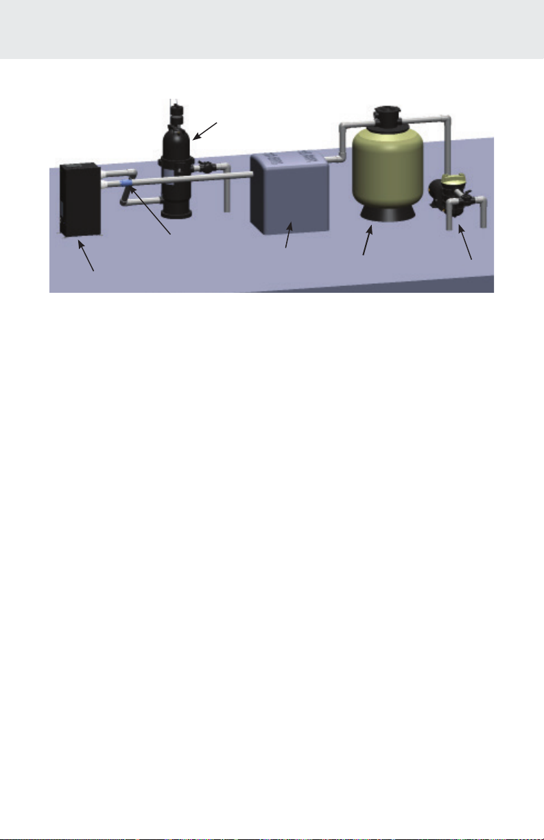
• Install at least 5 feet (1.5 meters) from wall of pool. Install ozone
generator no less than one (1) foot above maximum water level
to prevent water from contacting electrical equipment. Install in
accordance with the installation instructions.
• Follow all applicable electrical codes.
• DANGER ELECTRIC SHOCK HAZARD: Be sure to turn power
OFF and disconnect from power source before any service work is
performed. Failure to do so could result in serious injury or death.
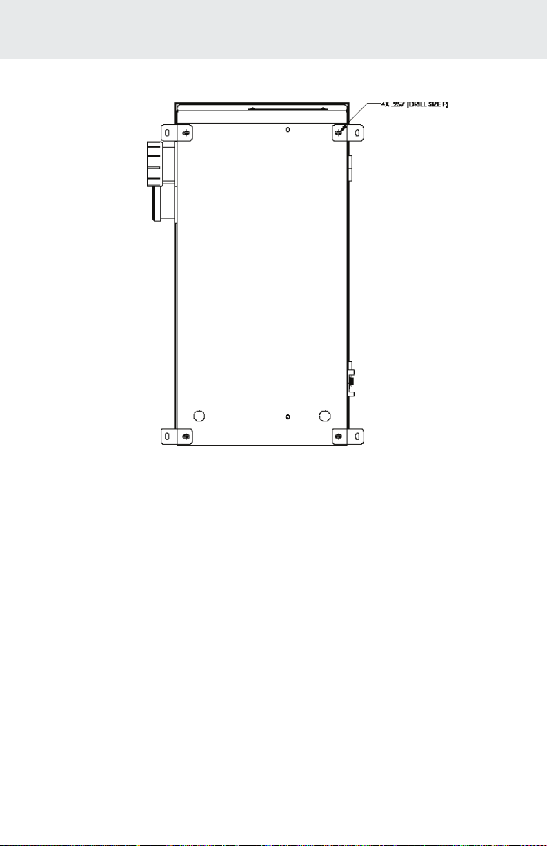
• The DEL AOP 50 must be installed in an outdoor location, or indoors
in a forced air ventilated room, and installed so that the orientation
is exactly as shown in Figure 3. Install to provide water drainage of
generator to protect electrical components.
• Mount the DEL AOP 50 so that it is inaccessible to anyone in the pool.
Never attempt any servicing while unit is wet.
IMPORTANT INFORMATION

• WARNING Short-term inhalation of high concentrations of ozone
and long term inhalation of low concentrations of ozone can cause
serious harmful physiological eects. DO NOT inhale ozone gas
produced by this device.
• For your safety, do not store or use gasoline, chemicals or other
ammable liquids or vapors near this or any other appliance.
• To maintain cosmetic integrity, protect this unit from direct prolonged
sunlight exposure.
• To reduce the risk of injury, do not permit children to use this product,
unless they are closely supervised at all times.
• ENVIRONMENTAL NOTICE - Hg-Lamp CONTAINS MERCURY.
Manage in accordance with disposal laws.
See: www.lamprecycle.org
• If unit is not operated according to instructions, high dosages of
harmful substances may potentially be released.
SAVE THESE INSTRUCTIONS!

TABLE OF CONTENTS
SECTION 1 General Information
1A. Description .................................................................................1
1B. Specications.............................................................................1
SECTION 2 Installation
2A. Pool Preparation...................................................................... 2
2B. Location...................................................................................... 2
2C. Mounting ................................................................................... 3
2D. Electrical ..................................................................................... 3
2E. Plumbing.................................................................................... 4
SECTION 3 Operation
3A. Initial System Start-Up ........................................................... 5
3B. Normal Operation................................................................... 6
3C. System Shut-Down.................................................................. 6
3D. Winterizing ................................................................................ 6
3E. Water Chemistry...................................................................... 7

TABLE OF CONTENTS
SECTION 4 Maintenance & Service
4A. System Electromechanical Overview................................. 7
4B. System Maintenance .............................................................. 9
4C. Ozone Module Servicing ...................................................... 9
4D. UV Reactor Service & Maintenance ................................. 11
SECTION 5 Troubleshooting
5A. Troubleshooting......................................................................15
SECTION 6 Contact Information
6A. Contact Information ..............................................................16
6B. Ordering Information............................................................16
6C. Standard Replacement Parts List.......................................16
Appendix A: Installation Plumbing ...........................................17
Appendix B: Ozone Cell Cleaning ............................................19
Appendix C: Pressure Drop Curve ............................................21
Appendix D: In-Place Quartz Tube Cleaning........................22

1
Section 1 General Information
1A. Description
The DEL AOP 50 Ozone and UV Sanitizer System described in this
manual is designed to provide the benets of ozonated and UV
treated water in an environmentally safe and eective manner. The
high quality, specially engineered components ensure ecient water
sanitation output and reliable performance. As a result of proper
use, the DEL AOP 50 virtually eliminates the unpleasant eects of
traditional chemicals. The DEL AOP 50 ozone generators are safe and
harmless to your equipment when installed properly.
1B. Specications
Power Requirements:
240V, 60 Hz, 1Ø, 0.6 Amp
Shipping Weight:
Approx: 54lbs/25.5kg
LocationRequirements:
Mounting: Floor Mounted
Ambient Temp.: 30°F - 120°F (0°C - 50°C)
MaxFlowRate(forNSF50compliance):
189 LPM (50 GPM)
This product is designed for supplemental disinfection and should
be used with registered or approved disinfection chemicals to impart
residual concentrations.
NSF/ANSI 50, Section 13 disinfection ecacy testing for 3-log (99.9%)
or greater of Pseudomonas, Aeruginosa and Enterococcus Faecium.
Specic residual levels of EPA registered disinfection chemicals may be
required by the regulatory agency having authority.

2
Section 2 Installation
2A.PoolPreparation
To achieve optimal performance from the ozone system, the pool
must be as clean as possible to start with.
1. Backwash or clean lters one day before starting the ozone
generator.
2. Superchlorinate pool water using a chlorine based shock
treatment so the water has a sustained 1-3 ppm free chlorine
level.
3. Test pool chemistry and adjust pH between 7.4 and 7.6. Adjust
total alkalinity between 80 and 120 ppm.
4. Run pool ltration continuously for 24 hours prior to starting
ozone system.
2B. Location
The DEL AOP 50 unit is designed for oor mounting. Locate the unit
in a clean, protected area, either indoors or outdoors (preferably
out of direct sunlight). If possible, locate the unit out of reach of
sprinklers or drainage spouts. Allow sucient access for maintenance
(2 ft clearance above and 1 ft around the unit) and all plumbing and
electrical hookups.
Figure 1: Overview
LAMP ACCESS
PANEL
INLET
OUTLET
INDICATOR
LIGHTS
WARNING
LABELS
GROUNDING
LUG
KNOCKOUTS
(1/2” CONDUIT)
FUSE
MOUNTING FEET
KNOCKOUTS
(1/2” CONDUIT)

3
Section 2 Installation
2C. Mounting
2C-1.FloorMounting
The DEL AOP 50 is shipped with the Mounting Feet installed in the
oor mounting position. Adjust the position of the feet if necessary
and tighten the screws. Mount the DEL AOP 50 to the equipment pad
through the slots provided in the feet using appropriate hardware for
the mounting surface.
2C-2.WallMounting
The DEL AOP 50 unit does not have holes for wall mounting but can
be mounted on the wall if desired.
1. Drill 4 holes, (.257 in, drill size F), in the back of the enclosure
approximately as shown in Figure 2.
2. Open door as described in SECTION 4C-1 and clean out debris.
3. Install Mounting Feet in drilled holes with hardware provided.
4. Mount unit to wall through the slots in the Feet using appropriate
hardware for the mounting surface.
2D.Electrical
2D-1.MainPower
Connect the DEL AOP 50 to the pool timing clock so that the DEL AOP
50 operates simultaneously with the pool pump. The DEL AOP 50 has
four available Knockouts for a 1/2” conduit tting, two on the back and
one on each side. Remove only the ideal Knockout for the installation
and install the proper conduit tting. Remove the Cover (Refer to
SECTION 4C-1) and locate the Terminal Block (Refer to Figure 5) on
the left side of the enclosure. Connect Line 1, Line 2, and Ground to
the Terminal Block as indicated by the label on the Generator Bracket.
Refer to the IMPORTANT SAFETY INSTRUCTIONS at the beginning
of this manual for important wiring information.
2D-2. Grounding Lug
Using a solid copper conductor, connect to the Grounding Lug on the
left side of the DEL AOP 50 to an appropriate earth contact.

4
Section 2 Installation
2E. Plumbing
The DEL AOP 50 can easily be added into the pool’s plumbing loop.
All the components are contained inside the enclosure so only the
water inlet and outlet need to be installed into the pool’s return line.
2E-1.PlumbingtheDELAOP50
The DEL AOP 50 must be installed in the pool’s main return line after
all other pool equipment (pump, lter, heater, and cleaner). The outlet
of the SEC (or MDV-100) must be at least 10 feet from the rst return
to the pool. Figure 3 shows the most basic installation. For installation
with additional sanitizers and pool cleaners, refer to Appendix A.
The DEL AOP 50 will come with one half of a union tting installed on
Inlet and Outlet, the other half of the ttings will be located in the DEL
AOP 50 parts bag. Use the union ttings provided to connect the DEL
AOP 50 inlet and outlet to your pool’s plumbing as shown in Figure 3.
Figure2:WallMountingHolePattern

5
Section 3 Operation
2E-2.PlumbingtheMixingDegasVessel(optional)
Under normal operation of the DEL AOP 50, bubbles will appear in
the return ow to the pool. To remove the bubbles from the ow, an
accessory Mixing Degas Vessel, or MDV, can be installed downstream
of the DEL AOP 50. The MDV-100 is designed for use with the DEL
AOP 50 and is recommended on indoor, covered, or vinyl-lined
pools. For more information, please call 1 (800) 676-1335 and ask for
Residential Technical Support.
2E-3.WaterBackowCheckValve
If the pool equipment is mounted above the water line, a check valve
must be installed between the pump outlet and the Injector Manifold to
prevent the pump from draining and losing its prime (when not in use).
NOTE:If a 1/3# DELCheckTM is used, do not install immediately after
chlorine feeders.
3A.InitialSystemStart-Up
Upon completing all of the system connections and cleaning the pool
as outlined in SECTION 2, you are ready to start the DEL AOP 50.
1. Check electrical connections.
2. Turn on pool circulation system and verify the DEL AOP 50 has
power.
Figure3:DELAOP50LocationinPoolLoop
DEL AOP 50
WATER BACKFLOW CHECK
VALVE (OPTIONAL)HEATER FILTER PUMP
MDV-100
(OPTIONAL)

6
Section 3 Operation
3. Remove cover. Conrm that ttings are not leaking, contact Tech
Support at 1 (800) 676-1335 if leaks are found.
4. Replace cover.
3B. NormalOperation
Indicator Lights: The DEL AOP 50 has two external indicator lights,
red and green, on its left side. When the DEL AOP 50 has power, the
green Power Light will illuminate. The red Flow Indicator may be on
momentarily. Once adequate water is owing, the red Flow Indicator
will go out. If the red Flow Indicator light is still lit after the pump has
reached steady ow, refer to Trouble Shooting (SECTION 5).
3C. SystemShut-Down
The following sequence of steps must be followed for servicing or for
storage.
1. Shut o power at the breaker.
2. Shut o water to the unit.
3. Open door.
4. Disconnect all electrical, plumbing, and mounting connections for
storage.
3D. Winterizing
If the pool will be shutting down for the winter months and the DEL
AOP 50 will remain exposed to freezing temperatures, the unit must
be drained to prevent freeze damage to the wetted components. To
drain the DEL AOP 50, see the following steps.
1. If the DEL AOP 50 is mounted below the water level, bypass valves
must all be CLOSED to prevent excess water from draining into
the unit.
2. Open the door.
3. Locate the Drain Plug (Refer to Figure 7) and remove to drain the
remaining water in the DEL AOP 50.
4. Allow all the water to drain from the DEL AOP 50 before threading
the plug back into the UV Reactor.

7
Section 4 Maintenance & Service
3E. WaterChemistry
Regular chlorine testing should be performed as normal. Ozone will
be eliminating the majority of contaminants. Therefore, only a small
amount of chemicals will need to be added – just enough to maintain
a residual level of 0.5 - 1.0 ppm free chlorine. Ozone is pH neutral and
will not cause pH or total alkalinity uctuations.
4A.SystemElectromechanicalOverview
CAUTION Disconnect power before performing service. Refer to
the IMPORTANT SAFETY INSTRUCTIONS displayed in the front of
this manual.
Refer to Figures 4, 5, and 6.
4A-1.OzoneModule
The DEL AOP 50 is constructed with 6 Corona Discharge Ozone
Modules. Each Ozone Module has a green light to indicate that the
Ozone Power Supply is operating properly (Refer to Figure 5 for a
more detailed view).
4A-2.UltravioletLamps
There are two lamps in the UV Reactor of the DEL AOP 50. If the UV
Lamp Access Panel is removed while the unit is running, a slight glow
can be seen near the top of the lamps (Refer to Figure 6 for a more
detailed view).
4A-3.InjectorManifold
Water owing through the Injector Manifold generates the vacuum
that draws ozone into the water. The DELCheck™ spring loaded valve
automatically adjusts for various water ow rates to keep the DEL AOP
50 operating over a wide range of conditions.
4A-4.OzoneGasLine
Gas from the Ozone Modules is drawn through the Ozone Gas Line
by the Injector and into the water. The Ozone Check Valve in this line
prevents water from migrating back to the Ozone Modules when the
DEL AOP 50 is not running.

8
Section 4 Maintenance & Service
4A-5.OzoneModuleFiltersandOrice
The air entering the Ozone Modules passes through individual Filters
and an Orice on each Module inlet. The Filters and Orices are
held in place by the rubber Filter Cap. (Refer to Figure 5 for a more
detailed view)
4A-6.InjectorTubeAdapter
This connects the Ozone Gas Line to the Injector Manifold. When
servicing this component, do not tighten past 10 in-lbs or the
component may be damaged.
OZONE
GENERATOR
ASSEMBLY
OZONE GAS
LINE
UV REACTOR
DEL CHECK VALVE
INJECTOR
MANIFOLD
FLOW SWITCH RELAY
NOTE: BALLAST LOCATED
ON ENCLOSURE CEILING
NOT SHOWN
FLOW SWITCH
INJECTOR TUBE
ADAPTER
Figure4:DELAOP50Electro-MechanicalOverview

9
Section 4 Maintenance & Service
4B. SystemMaintenance
Use a size 2 phillips driver to remove the UV Access Panel or a at tool
to open the Enclosure Cover as needed.
NOTE:The DEL AOP 50 will not operate until the UV access panel is
replaced.
4B-1.OzoneModuleMaintenance
The green Ozone Module Lights on the Ozone Modules indicate that
the Ozone Power Supply is operating properly. When an indicator
light goes out, replace the corresponding Ozone Module.
4B-2.OzoneModuleReplacementInterval
Ozone module life expectancy is 5 years. Even if the Ozone Module
Light(s) are glowing, the Ozone Module may be producing little or
no ozone after this period of time due to contamination within the
corona discharge ozone chamber.
4B-3.OzoneGasLineReplacementInterval
Replace the Ozone Gas Line every year or sooner, if needed. If there is
evidence of water leaking past the Ozone Check Valve toward the Ozone
Modules, shut down the DEL AOP 50 immediately and replace the Ozone
Gas Line. If water entered the Ozone Modules, run the ltration system
so air will be drawn through the Ozone Modules and they can dry out.
Ozone Modules will return to normal operation when dry.
WARNING Trace amounts of nitric acid may be present in the
Ozone Gas Line. Wear proper safety equipment (gloves and eye
protection) and avoid direct contact with any condensation in the line.
4C. OzoneModuleServicing-RefertoFigure 5
4C-1. Opening the Door
The DEL AOP 50 may be serviced without disconnecting any of the
plumbing or wiring. Simply use a slotted screwdriver to turn the door
latches a half turn counter clockwise and open the door. Reverse the
steps to securely close the door.

10
Section 4 Maintenance & Service
4C-2.ReplacinganOzoneModule
1. Open the DEL AOP 50 as described in SECTION 4C-1.
2. Locate the Ozone Modules on the left wall of the enclosure.
3. Remove the Filter Cap Assembly from the right tube tting of the
Ozone Module. Make sure you keep the Cap, Filter and Orice
together.
4. While holding the Ozone Outlet Manifold, gently pull the left tube
tting out of the manifold and both tube ttings through the holes
in the Ozone Module Bracket. Let the Ozone Module hang down.
5. Disconnect the Ozone Gas Line and unscrew the two front
mounting screws of the Ozone Bracket. Swing the ozone Bracket
forward and locate the Power Connector (black and red wires)
from the Module Power Supply and disconnect from the wire
harness. Refer to Figure 6.
6. Unscrew the Ozone Module from the Module Bracket and remove
the Module assembly from the unit.
7. Install the new Ozone Module by reversing the above steps. Refer
to Figure 5 for visual instruction. Do not misplace spacer.
POWER
CONNECTOR
FILTER
OZONE
OUTLET
MANIFOLD
TERMINAL
BLOCK
OZONE
MODULE
OZONE
MODULE
LIGHT
MODULE POWER
SUPPLY
TUBE
FITTING
Figure5:OzoneGeneratorSubassembly
CAP
ORIFICE
SPACER

11
Section 4 Maintenance & Service
4D.UVReactorServiceandMaintenance
The UV Lamps are housed in a Quartz Tube. If the Quartz Tube
becomes dirty, its ability to transmit UV rays from the Lamp will be
diminished. The Quartz Tube(s) should be removed from the UV
Reactor every six (6) months and cleaned if necessary.
4D-1LampRemoval
1. Locate the UV Lamp Access Panel on the top of the DEL AOP 50,
remove the 4 screws with a Phillips head screwdriver, and remove
the panel.
2. After allowing adequate time for the lamps to cool, disconnect
the Lamp Connectors from Ballast wires.
3. Grasp the UV Lamp wires and gently pull until the top of the UV
Lamp has pulled past the Lamp Retainer tabs.
4. By holding the UV Lamp’s white ceramic end, slowly pull the UV
Lamp until the bottom has pulled past the Lamp Retainer tabs. DO
NOT TOUCH THE UV LAMP GLASS WITH YOUR BARE HANDS.
Oils on your hands can cause hot spots on the UV Lamp and shorten
its life. Use a soft clean cotton cloth or clean cotton gloves to handle
the UV Lamp. Carefully place the UV Lamp in a clean, dry, and safe
location. Repeat this process for the other UV Lamp.
Figure6:OzoneBracketDuringOzoneModuleService

12
Section 4 Maintenance & Service
4D-2QuartzTubeRemovalandCleaning
NOTE:For instructions on cleaning without mechanical disassembly,
see Appendix D.
NOTE:If the DEL AOP 50 is installed below water level, the bypass valves
must all be CLOSED to prevent excess pool water from draining into the
open unit when a Quartz Tube is removed.
1. Before continuing, allow adequate time for the Quartz Tubes to cool
and drain the water from the UV Reactor by removing the Drain Plug
and replacing it once water has stopped exiting the UV Reactor.
2. After removing the lamps, remove the top Lamp Retainer Screws
using the hex key included in the parts bag. Place the Lamp Retainer
Screws, Washers, and the Lamp Retainer aside in a safe place.
3. Using the hex key included in the parts bag, loosen the bottom
Lamp Retainer Screws two full rotations.
4. Grasp the Quartz Tube from the top of the UV Reactor, and pull to
remove it from the UV Reactor.
5. Remove the Sealing O-Ring from the top of the Quartz Tube and
set aside in a safe place. NOTE:O-Rings in the bottom Endcap of
the Reactor do not need to be removed for Quartz Tube Service.
6. Clean the Quartz Tube exterior with a mild solution of muriatic acid
(available at all pool supply stores) and water in a ratio of four parts
water to one part acid (4:1).
Figure7:UVReactorSubassembly
LAMP CONNECTOR
LAMP RETAINER SCREWS
UV REACTOR
DRAIN PLUG
LAMP
RETAINER SEALING O-RING
WASHERS

13
Section 4 Maintenance & Service
CAUTION Follow the directions for use and handling of muriatic
acid on the acid bottle label, being careful to protect your eyes, wear
rubber gloves, and avoid breathing acid fumes.
NOTE:DO NOT USE ABRASIVE CLEANERS as they can scratch
the high quality quartz glass. If lime or hardwater calcium deposits
are encountered, use household tub and shower lime removal. After
cleaning the Quartz Tube, wash it o and wipe dry. Inspect the Quartz
Tube for cracks. Replace if cracks are found. Make sure the inside of
the Quartz Tube is dry before replacing the UV Lamp(s).
NOTE:DAMAGES CAUSED BY BROKEN QUARTZ TUBES ARE NOT
COVERED UNDER YOUR LIMITED WARRANTY.
4D-3QuartzTubeInstallation
1. While holding the Quartz Tube so it is oriented straight up and
down, insert the Quartz Tube into the UV Reactor until it is fully
seated in the bottom of the UV Reactor.
Note: If the end of the Quartz Tube is protruding from the UV
Reactor, the alignment is o. Remove and re-insert the Quartz
Tube to seat it properly as shown in Figure 8.
2. Place a Sealing O-Ring approximately 1/2in (12.7mm) from the end
of the Quartz Tube protruding from the top of the UV Reactor.
3. Place the Lamp Retainer over the Quartz Tube and using the hex
key included in the parts bag, attach the Lamp Retainer to the UV
Reactor using the Lamp Retainer Screws and Washers as shown
in Figure 7. Make sure the Lamp Retainer anges are fully seated
against the UV Reactor.
4. Turn the circulation pump ON and check the Quartz Tube seal for
leaks.
5. Turn the circulation pump OFF once you have conrmed that the
Quartz Tube is not leaking.

14
Section 4 Maintenance & Service
4D-4Re-installingtheUVLamp(s)
NOTE:Make sure to handle the UV lamp as described in SECTION 4D-1.
1. TURN OFF YOUR PUMP IF YOU HAVE NOT DONE SO.
2. Slowly press the UV Lamp fully past the Lamp Retainer tabs and
into the Quartz Tube until it is seated on the Lamp Cushion in the
bottom of the tube.
3. Connect the Lamp Connector to the connector on the Ballast
NOTE:To replace a UV Lamp, follow only SECTIONS 4D-1 and 4D-4.
ENVIRONMENTAL NOTICE: Hg-Lamp CONTAINS MERCURY.
Manage in accordance with disposal laws. See: www.lamprecycle.org
Figure8:UVQuartzTubeInstallation
IMPROPERLY
SEATED QUARTZ
TUBE
PROPERLY
SEATED QUARTZ
TUBE

15
Section 5 Troubleshooting
5A.Troubleshooting
Knowledge of electrical applications is required for trouble shooting.
Contact a certied electrician if you are unsure of your ability to
service the equipment. Improper servicing will void generator
warranty. If any condition persists contact DEL Technical Support (see
SECTION 6A).
Symptom: Green Indicator not lit when pool system is on.
1. No power to the DEL AOP 50 from the Power Source:
a. Check circuit breaker at the power distribution box.
b. Check for loose connections or wiring breaks in the lines
leading to the Terminal Block.
c. Fuse in the unit has blown and needs to be replaced. Fuse is a
1 Amp slow blow, 1/4” x 1.25” long, glass fuse.
d. Indicator lights have burnt out.
Symptom: Red Indicator will not go out.
1. Insucient ow through DEL AOP 50.
a. Verify that pump is running properly and that lter and
skimmers are clean.
2. Clear any blockages in return line.
3. Flow Switch has failed and needs to be replaced.
4. Flow Switch Relay has failed and needs to be replaced.
Symptom: Green Ozone Module Light is not illuminated when unit is
running.
1. This means that the power supply of that specic Ozone Module
is no longer drawing power and needs to be replaced. Refer
to SECTION 4C-2 for instructions on how to replace the
corresponding Ozone Module.
Symptom: One or both the UV Lamps are not lit when unit it running.
1. Check Lamp Connector Plug for complete connection.
2. Water fouling has shorted lamp connections.
3. Bad UV Lamp.
4. Bad Ballast.
Other manuals for DEL AOP 50
1
Table of contents
Other CMP Accessories manuals
Popular Accessories manuals by other brands

Honeywell
Honeywell TC840ME Installation and maintenance instructions

Vega
Vega VEGADIS 81 operating instructions

Califone
Califone LP4 user manual

Suez
Suez CheckPoint Pharma Owner's operation and maintenance manual

IntelliSense
IntelliSense DT-725D DUAL TEC installation instructions

Silvercrest
Silvercrest 284941 Assembly, operating and safety instructions