CMP DEL UV-C PRO 50 User manual

4-2839-01 Rev.A
CMPCOMMERCIAL.COM
DEL UV-C PRO (50, 100)
INSTALLATION INSTRUCTIONS & PRODUCT MANUAL
®

READ AND FOLLOW ALL INSTRUCTIONS
• Read this manual completely before attempting installation. Failure to install in accordance with
the installation instructions could void warranty and result in injury or death.
• All permanent electrical connections should be made by a qualied electrician.
• A pressure wire connector, labeled bonding lugs, is provided on the outside of the unit to
permit connection to a minimum No. 6 AWG (13.3 mm2) solid bonding conductor between this
point and any metal equipment, metal enclosures of electrical equipment, metal water pipes, or
conduit within 5 feet (1.5 meters) of the unit as needed to comply with local requirements.
• Install at least 5 feet (1.5 meters) from wall of pool.
• Follow all applicable electrical codes.
• DANGER ELECTRIC SHOCK HAZARD:Be sure to turn power OFF and disconnect from power
source before any service work is performed. Failure to do so could result in serious injury or
death.
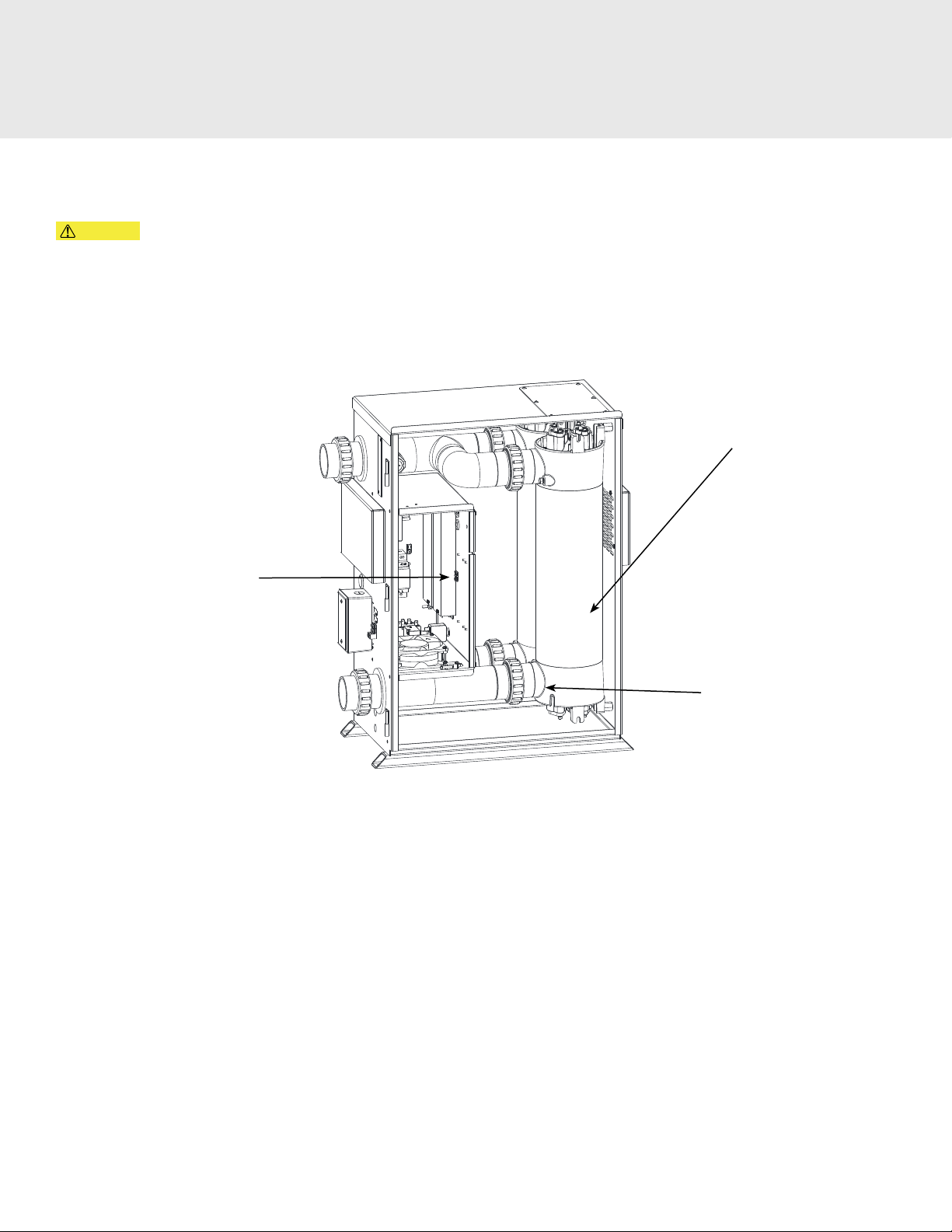
• The UV-C Pro must be installed in an outdoor location, or indoors in a forced air ventilated room,
and installed so that the orientation is exactly as shown in Figure 4. Install to provide water
drainage of generator to protect electrical components.
• Mount the UV-C Pro so that it is inaccessible to anyone in the pool. Never attempt any servicing
while unit is wet.
• For your safety, do not store or use gasoline, chemicals or other ammable liquids or vapors near
this or any other appliance.
• To maintain cosmetic integrity, protect this unit from direct prolonged sunlight exposure.
• To reduce the risk of injury, do not permit children to use this product, unless they are closely
supervised at all times.
• ENVIRONMENTAL NOTICE: Hg-Lamp CONTAINS MERCURY. Manage in accordance with
disposal laws.
See: www.lamprecycle.org
• If unit is not operated according to instructions, high dosages of harmful substances may
potentially be released.
• Product has met the requirement of NSF/ANSI 50, Annex H.1 for supplemental disinfection and
is designed for pools that are in compliance with the U.S. Model Aquatic Health Code (MAHC).
Installed ow rates must not exceed max listed ow rates to maintain NSF product listing as well
as ensuring proper microbial performance.
• NSF/ANSI 50, Section 13 disinfection ecacy testing for 3 log (99.9%) or greater of Pseudomonas
Aeruginosa and Enterococcus Faecium. Specic residual levels of EPA registered disinfection
chemicals may be required by the regulatory agency having authority. Product is designed for
supplemental disinfection and should be used with registered or approved disinfection chemicals
to impart residual concentrations.
SAVE THESE INSTRUCTIONS!
IMPORTANT INFORMATION

TABLE OF CONTENTS
1 General Information
1A. Description .....................................................................................................................................1
1B. Specications.................................................................................................................................1
2 Installation
2A. Pool Preparation.......................................................................................................................... 2
2B. Location.......................................................................................................................................... 2
2C. Mounting ....................................................................................................................................... 2
2D. Electrical ......................................................................................................................................... 2
2E. Plumbing........................................................................................................................................ 3
3 Operation
3A. Initial System Start-Up ...............................................................................................................4
3B. Normal Operation.......................................................................................................................4
3C. System Shut-Down...................................................................................................................... 6
3D. Water Chemistry.......................................................................................................................... 6
4 Maintenance & Service
4A. UV Reactor System Electromechanical Overview ............................................................. 7
4B. UV Reactor Service & Maintenance ...................................................................................... 7
4C. PLC Memory Battery Backup Replacement...................................................................... 10
4D. Winterizing .................................................................................................................................. 10
5 Troubleshooting & Resources
5A. Troubleshooting.......................................................................................................................... 11
5B. Contact Information ................................................................................................................. 12
5C. Ordering Information............................................................................................................... 12
5D. Standard Replacement Parts List.......................................................................................... 12
Appendix A: Pressure Drop Curve....................................................................................................... 13
Appendix B: In-Place Quartz Tube Cleaning .................................................................................... 14

1
1A. Description
DEL UV-C Pro products use UV-C light to provide superior disinfection of pool and spa water. The system utilizes low pressure
(254 nm) lamps in a modular design to provide a completely integrated system. Controls and UV-C reactors are all in one
cabinet.
With the use of UV-C microorganisms are destroyed, chlorine dependence is signicantly reduced, and water clarity is
optimized to produce crystal clear results.
UV-C is compatible with all traditional sanitizers. These systems are cost eective to operate and maintain. UV-C Pro is NSF
certied for supplemental disinfection of pools and spas.
UV-C PRO-50 UV-C PRO-50D UV-C PRO-100 UV-C PRO-100D
FLOW 20-50 GPM 20-100 GPM
INLET/OUTLET 2in 2in
UV LAMP QTY 2 4
PLC CONTROL No Yes No Yes
VOLTAGE 120VAC 120VAC
CURRENT 1.1A 1.6A 1.9A 2.4A
Table 1: UV-C Pro Sizing Chart
1B.Specications
See Table 1 for list of models and specs that apply to this manual. Images shown are model UV-C PRO-100D but manual
instructions apply to all models, unless otherwise noted.
Control Interface
(PLC Option Shown)
Water Outlet
Water Inlet
Access Door
Panel
Bonding
Lug
Figure 1: UV-C Generator Overview
1. GENERAL INFORMATION

2
2A. Pool Preparation
To achieve optimal performance from the system, the pool must be as clean as possible to start with.
1. Backwash or clean lters one day before starting the generator.
2. Superchlorinate pool water using a chlorine based shock treatment so the water has a sustained 1-3 ppm free
chlorine level.
3. Test pool chemistry and adjust pH between 7.4 and 7.6. Adjust total alkalinity between 80 and 120 ppm.
4. Run pool ltration continuously for 24 hours prior to starting UV-C Pro.
2B. Location
• Ambient Temp.: 40°F - 110°F (5°C - 43°C)
• Locate the unit indoors or outdoors in a clean area protected from rain and direct sunlight.
• Locate the unit out of reach of sprinklers or drainage spouts. Allow sucient access for maintenance (2 ft clearance
above and 1 ft around the unit) and all plumbing and electrical hookups. Allow additional clearance in front of the
unit to allow for door swing and lamp service.
2C. Mounting
• The UV-C Pro is shipped with hardware for either oor or wall mounting. Attach the mounting rails in the desired
position (bottom or back of the enclosure) and secure with the screws provided.
• Mount the UV-C Pro securely using appropriate hardware or anchors for the surface and as needed to meet local
building code requirements.
2D. Electrical
Refer to the IMPORTANT SAFETY INSTRUCTIONS at the beginning of this manual for important wiring information.
2D-1. Main Power
• Connect the UV-C Pro so that it operates simultaneously with the pool pump.
• An electrical junction box and wires are provided on the left wall of the enclosure for a 1/2” conduit connection.
• Remove the protective plug and install electrical ttings as required to meet local codes.
• Run service wires to the box and connect to provided wiring.
2D-2. Bonding Lug
Connect a solid copper conductor to the bonding lug on the left side of the UV-C Pro to an appropriate earth contact.
(Figure 1)
2. INSTALLATION

3
2D-3. System Control
• Remote start contacts have been provided for remote ON-OFF operation of the UV-C Pro.
• These should be wired to an external device that closes when the pool pump is ON and opens when it is OFF.
• Failure to use the remote start contacts may result in damage to the unit not covered under warranty.
Figure 2: Remote Start Contact Locations
2E. Plumbing
The UV-C Pro can easily be added into the pool’s plumbing loop. All the components are contained inside the enclosure
so only the water inlet and outlet need to be installed into the pool’s return line.
2E-1. Plumbing the UV-C Pro
• Install in the main return line of the pool immediately after the lter and preferably before the heater.
• Install cleaners such as chlorinators after the UV-C Pro.
• The outlet of the UV-C Pro must be at least 10 feet from the rst return of the pool.
• Use the ttings provided in the parts kit to connect the UV-C Pro inlet and outlet to the plumbing.
2. INSTALLATION
Connection Points for
Remote Start Contacts

4
3A. Initial System Start-Up
Upon completing all system connections and cleaning the pool as outlined in SECTION 2, you are ready to start the UV-C Pro.
1. Ensure that power is removed from the UV-C and turn on the pool circulation system.
2. Conrm that all ttings are free of leaks both outside and inside the unit. Contact Technical Support if any leak is
discovered inside the UV-C Pro.
3. Close the enclosure door and start the circulation system.
4. Apply power to the UV-C Pro.
5. The system should now run normally.
3B. Normal Operation
3B-1. Standard User Interface (for models with PLC option, skip to Section 3B-2)
Indicator lights (standard): These indicator lights inform the operator of the real-time functional conditions of the UV-C Pro.
1. POWER: This indicator will illuminate when the input power has been supplied and the remote start contacts are
closed.
2. FLOW: This indicator will illuminate when water ow has been established.
3. UV-C: This indicator will illuminate when the UV system is active.
FIGURE 3: LED Indicator Interface (Included on Standard User Interface)
3B-2. HMI User Interface (included with PLC option):
The HMI (Human-Machine Interface) screen includes status indicators and text to communicate real-time system
conditions as well as access to historical data. The ve function buttons allow user navigation of the menus and user
input. The HMI display color will also change to alert the user of certain conditions as noted below.
NOTE: Not all menu items described below are available on all models.
1. Main Screen: Contains most of the information that is important to view during normal operation, including: text elds
for unit operational status, alerts, and service reminders. The unit will automatically return to the main screen after ve
minutes of inactivity on any other screen.
Example with Normal Operation Example with Fault Message
(Flashing Amber Backlight)
3. OPERATION

5
2. Screen Select Menu: This menu is accessed through the function button on any screen and allows navigating to the
other HMI screens.
Screen Select Menu UV Service Screen
3. UV Service Screen: Contains countdown timers that track the hours remaining until service is due on listed UV
components. Once service is complete, the user will use the specic function button to reset the corresponding service
countdown timer. The hours remaining on the countdown timers are used to determine service messaging and alert
reminders:
• More than 10% remaining = no banner message
• 10% remaining = “SERVICE SOON” banner message
• 5% remaining = “SERVICE REQUIRED” banner message
• 0% remaining = “SERVICE PAST DUE” alert banner message with yellow screen background
Fault Counters ScreenHistory Screen
4. History Screen: Contains the runtime hour meter of the unit and the fault history table.
• The runtime hour meter indicates the actual on time of the UV system, to the closest 1/10 hour.
• The fault history table will indicate the fault and the accompanying time stamp, which is relative to the runtime
hour meter.
• Up to ten faults are listed with the most recent at the top of the table.
• The function buttons allow navigation through the fault history table screens.
5. Fault Counters Screen: Contains a list of possible faults for the system (model dependent) and how many faults have
occurred. The fault count can be used during troubleshooting to identify common faults in the system. All fault counts
can be reset through the function key.
3. OPERATION

6
6. Banner Message: Located on the top of all screens, this eld will provide messages and alerts relative to the real-time
operation of the unit.
Banner Message
3C. System Shut-Down
Followed for servicing or storage.
1. Shut o water ow to the unit and/or close isolation valves if available.
2. Shut o power at the breaker.
3. Open enclosure door to access internal components.
NOTE: Water pressure may still be present depending on system plumbing. Ensure water pressure is relieved prior to
servicing any water plumbing components.
3D. Water Chemistry
The UV-C Pro will provide the benets of UV-C germicidal disinfection treatment with minimal impact to other water
chemistry parameters. However, chlorine or other sanitizer residual levels must be maintained as required to meet local
codes. Regular residual testing must be performed as usual.
3. OPERATION

7
4A. UV Reactor System Electromechanical Overview
CAUTION Disconnect power before performing service. Refer to the IMPORTANT SAFETY INSTRUCTIONS displayed in
the front of this manual. Refer to Figures 4, 5, and 6.
NOTE: To replace a UV lamp, follow only SECTIONS 4B-1 AND 4B-4.
There are two lamps in each UV reactor of the UV-C Pro powered by an energy ecient electronic ballast. Water enters the
UV reactor and is exposed to UV-C. The water exits through the top of the UV reactor and returns to the process plumbing.
UV Reactor
Figure 4: UV-C Pro Electro-Mechanical Overview
4B. UV Reactor Service and Maintenance
• Each UV Reactor contains two UV lamps and two quartz tubes.
• The UV lamps are designed to provide proper germicidal ecacy for 16,000 hours.
• The UV lamps may continue to glow well beyond 16,000 hours but will not provide proper intensity and must be
replaced to ensure ecacy.
• The UV lamps are housed in a quartz tube. If the quartz tube becomes dirty, its ability to transmit UV rays from the
lamp will be diminished.
• The service interval for the quartz tube is dependent on pool water chemistry and some pools may require more
frequent cleaning than others.
• Initially, inspect the quartz tube after 750 hours of use and clean as needed. Subsequent cleaning intervals can be
increased or decreased based on the condition of the quartz tubes or observed water conditions.
4. MAINTENANCE & SERVICE
Drain Plugs
(on backside - not shown)
Ballasts

8
Lamp Retainer
UV Service
Access Panel
Sealing O-ring
Lamp Retainer Screws
UV Lamp
Quartz Tube
Figure 5: UV Lamp and Quartz Tube Removal
CAUTION: Always disconnect power to the UV-C Pro prior to performing service.
4B-1. UV Lamp Removal
1. Remove the UV service access panel from the top of the enclosure.
NOTE: The UV-C Pro will not operate while the panel is removed.
2. After allowing adequate time for the UV lamps to cool, disconnect the UV lamp from the connector on the ballast.
3. Grasp the UV lamp wires and gently pull until the top of the UV lamp has pulled past the lamp retainer tabs.
4. Pull slowly on the white ceramic end of the UV lamp until the bottom has pulled past the lamp retainer tabs. If the
UV lamp is dicult to remove, use a slight twisting motion or remove the lamp retainer. AVOID TOUCHING THE
UV LAMP GLASS WITH YOUR BARE HANDS. Oils on your hands can cause hot spots on the UV lamp and shorten
its life. Use a soft clean cotton cloth or clean cotton gloves to handle the UV lamp. Carefully place the UV lamp in a
clean, dry, and safe location. Clean the UV lamp if necessary with alcohol and repeat this process for the other UV
lamps.
4B-2 Quartz Tube Removal and Cleaning
NOTE: For instructions on cleaning without mechanical disassembly, see Appendix.
1. If the UV-C Pro is mounted below the water level, system isolation valves must all be CLOSED to prevent excess water
from draining into the unit.
2. Loosen main inlet and outlet ttings on the UV-C Pro, this should allow sucient water to drain from the UV
reactor(s).
3. Before continuing, allow adequate time for the UV lamps and quartz tubes to cool.
4. Remove the UV lamps as described in Section 4B-1.
5. Remove the top lamp retainer screws using the hex key included in the parts kit and remove the lamp retainer.
6. Grasp the quartz tube from the top of the UV reactor, and pull to remove it from the UV reactor.
7. Remove the sealing O-ring from the top of the quartz tube and set aside.
8. Wipe all residue from the quartz tube. If calcium deposits are encountered, use a mild solution (4:1) of water and
muriatic acid (available at pool supply stores), or household calcium/lime remover.
Follow the directions for use and handling of muriatic acid on the acid bottle label. Use proper eye and skin
protection and avoid breathing acid fumes.
NOTE: DO NOT USE ABRASIVE CLEANERS as they can scratch the high quality quartz glass. After cleaning the quartz tube,
wash it o and wipe dry. Inspect the quartz tube for cracks. Replace if cracks are found. Make sure the inside of the quartz
tube is dry before replacing the UV lamp(s).
CAUTION
4. MAINTENANCE & SERVICE

9
NOTE: DAMAGES CAUSED BY BROKEN QUARTZ TUBES ARE NOT COVERED UNDER THE LIMITED WARRANTY.
4B-3 Quartz Tube Installation
1. Place a sealing O-ring approximately 1/2in (12.7mm) from the end of the quartz tube. Insert the quartz tube into the
UV reactor until it is fully seated in the bottom of the UV reactor.
NOTE: If the end of the quartz tube is protruding from the UV reactor, the alignment is o. Remove and re-insert the
quartz tube to seat it properly as shown in Figure 6.
2. Place the lamp retainer over the quartz tube and attach the lamp retainer using the lamp retainer screws and
washers as shown in Figure 6. Make sure the lamp retainer anges are fully seated against the UV reactor.
3. Tighten main inlet and outlet ttings on the UV-C Pro.
4. Turn the circulation pump ON and check the quartz tube seals for leaks.
5. Turn the circulation pump OFF once you have conrmed that the quartz tubes are not leaking.
Improperly Seated
Quartz Tube Properly Seated
Quartz Tube
Figure 6: UV Quartz Tube Installation
4B-4 Re-installing the UV Lamp(s)
NOTE: Make sure to handle the UV lamp as described in SECTION 4B-1.
1. TURN OFF YOUR PUMP IF YOU HAVE NOT DONE SO.
2. Slowly press the UV lamp fully past the lamp retainer tabs and into the quartz tube until it is seated on the lamp
cushion in the bottom of the quartz tube.
3. Connect the UV lamp connector to the connector on the ballast.
ENVIRONMENTAL NOTICE: Hg-Lamp CONTAINS MERCURY. Manage in accordance with disposal laws. See: www.
lamprecycle.org
4. MAINTENANCE & SERVICE

10
Figure 7: Battery Replacement
4C. PLC Memory Backup Battery Replacement (included with PLC option only)
1. On the top of the PLC, press the retaining clip on the battery door and swing the battery door open.
2. Remove the old battery from right side of the coin-type slot.
3. Install the new battery with the +, or at, side out.
4. Close the battery door so that it locks securely.
5. Make note of the date the battery was replaced (it must be performed annually).
4D. Winterizing
If the pool will be shutting down for the winter months and the UV-C Pro will remain exposed to freezing temperatures, the
unit must be drained to prevent freeze damage to the wetted components. To drain the UV-C Pro, see the following steps.
1. If the UV-C Pro is mounted below the water level, isolation valves must all be CLOSED to prevent excess water from
draining into the unit.
2. Loosen main inlet and outlet ttings on the UV-C-Pro, this should allow most water to drain from the UV reactor(s).
3. Open the door and locate the drain plug(s) (Refer to Figure 4 ) and remove to drain the remaining water in the UV
reactor(s).
Battery
4. MAINTENANCE & SERVICE

11
5A. Troubleshooting
Knowledge of electrical applications is required for troubleshooting. Contact a certied electrician if you are unsure of your
ability to service the equipment. Improper servicing will void generator warranty. If any condition persists contact CMP
Technical Support (see Section 5B).
Models with an HMI screen provide immediate text notication of all system alerts. Other alert messages may occur that are
not listed below. The HMI also includes alarm history and fault counters that may be accessed for further help as described
above.
Symptom: HMI screen or POWER indicator not lit when pool system is on.
1. No power to the UV-C Pro:
a. Check circuit breaker at the power distribution box.
b. Check for loose connections or wiring breaks in the main power wiring leading to the UV-C Pro.
c. Check internal circuit breaker.
d. POWER indicator is not functioning.
e. For units with an HMI screen, screen may be faulty.
2. Remote Start contacts are open (“SYSTEM WAITING ON REMOTE START…” message on HMI). Verify that Remote Start
contacts are wired and operating properly.
Symptom: “WAITING ON SYSTEM FLOW” message on HMI screen or FLOW indicator not lit.
1. Insucient ow through UV-C Pro.
a. Verify that the main system pump is running properly and that lter and skimmers are clean.
b. Verify that pool valves have not been adjusted to limit ow below the minimum requirement.
2. Clear any blockages in return line.
3. Verify proper operation of ow switch.
Symptom: “LOW SYSTEM PRODUCTION…” message on HMI screen or UV-C indicator not lit.
1. Check UV lamp connector plug for complete connection.
2. Bad UV lamp. Replace UV lamp(s)
3. Bad ballast. Replace ballast(s).
5. TROUBLESHOOTING & RESOURCES

12
5B. Contact Information:
For technical assistance:
• Call: 1-800-733-9060
• Visit: www.cmpcommercial.com
Be prepared with the following information:
• Name
• Address
• Model #
• Date Purchased
5C. Ordering Information:
To locate a dealer nearest you call 1-800-733-9060 or visit www.cmpcommercial.com.
5D. Standard Replacement Parts List
DESCRIPTION PART NUMBER REPLACEMENT INTERVAL
UV LAMP REPLACEMENT KIT 9-1226-01 (EA) 16,000 Hours
QUARTZ TUBE REPLACEMENT KIT 9-1701-01 (EA) As Needed
PLC MEMORY BACKUP BATTERY
(included with PLC option only) 5-1402 Yearly
Table 2: Replacement Parts
NOTE: The warranty is void if the parts listed above are not replaced at recommended intervals.
5. TROUBLESHOOTING & RESOURCES

13
UV-C Pro Pressure Drop Characterization
NOTE:Tested on simulated recirculation system using a variable speed pump. No back pressure added. Actual results will vary
depending on pump and plumbing variables.
APPENDIX A

14
In-Place Quartz Tube Cleaning
The UV-C Pro quartz tubes may be cleaned without removing them from the vessel.
1. Ensure that the UV-C Pro is isolated from the rest of the pool system with valves at the inlet and outlet.
a. Connect to the inlet/outlet unions.
b. Flow the cleaning solution from bottom to top.
2. When cleaning is complete, drain the UV-C Pro completely from the inlet union and run the pool system
immediately for an extended period to fully rinse the internal components.
a. Special considerations may apply depending on the cleaning system.
b. Contact Customer Service if there is any question about compatibility with the UV-C Pro components.
APPENDIX B
Inlet Union
Outlet Union

15
NOTES
SAVE THESE INSTRUCTIONS
Record Information on this System Below & Keep for Your Records
Installer _______________________________________________________________
System Purchased From ______________________________________________
Installation Date _____________________________
Serial Number _______________________________

16
NOTES

CMP, LLC
36 HERRING ROAD, NEWNAN, GA 30265
WWW.CMPCOMMERCIAL.COM
0821ab
This manual suits for next models
3
Table of contents
Other CMP Accessories manuals