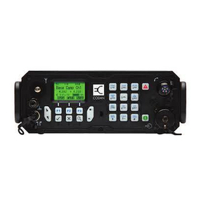
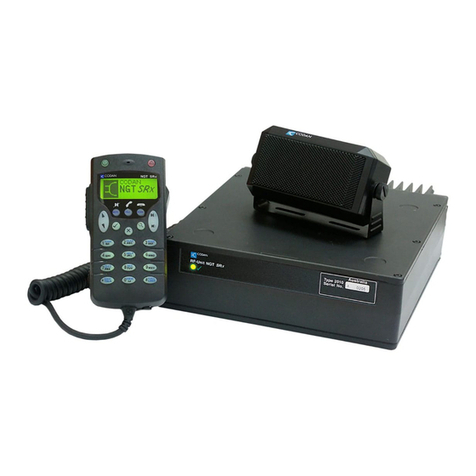
Codan X-2 User manual

X-2 HF SSB Transceiver
Technical service manual
1992, 1993 Codan Pty Ltd.
ACN 007 590 605
Order code 15-02047
Issue 2, October 1993

Head Office International Marketing Offices
Codan Pty Ltd
81 Graves Street
Newton
SOUTH AUSTRALIA 5074
Telephone
National 08 336 0311
International +61 8 336 0311
Facsimile 08 337 6090
Australia, Pacific and South East Asia
Codan Pty Ltd
Suite 24, 818 Pittwater Road
Dee Why
New South Wales
AUSTRALIA 2099
Telephone
National 02 971 2233
International +61 2 971 2233
Facsimile 02 982 1117
Telex 22631
Africa, Europe and The Middle East
Codan (U.K.) Ltd
6 Grove Park
Mill Lane
Alton, Hampshire GU34 2QG
UNITED KINGDOM
Telephone
National 0420 80121
International +44 420 80121
Facsimile 0420 541098
Telex 858355
North and South America
Codan Pty Ltd
Suite 101
8011 Leslie Road
Richmond BC V6X 7E4
CANADA
Telephone
National 604 270 8332
International +1 604 270 8332
Facsimile 604 270 4401

Publication No: 15-02047
Table of Contents
1Introduction........................................................................................................1-1
1.1 Purpose...........................................................................................................1-1
1.2 How this manual is organised..........................................................................1-1
1.3 Conventions....................................................................................................1-2
1.4 Related Documents.........................................................................................1-2
1.5 Overview ........................................................................................................1-2
1.6 Specifications..................................................................................................1-3
1.6.1 General Specifications.................................................................1-3
1.6.2 Receiver Specifications...............................................................1-5
1.6.3 Transmitter Specifications...........................................................1-6
2Brief Description............................................................................................2-1
2.1 General...........................................................................................................2-1
2.2 Control and Switching.....................................................................................2-2
2.3 Synthesiser......................................................................................................2-2
2.4 Receive Path...................................................................................................2-3
2.5 Transmit Path..................................................................................................2-4
3Operating Instructions...............................................................................3-1
4Technical Description................................................................................4-1
4.1 Control and Supply Voltages...........................................................................4-2
4.1.1 Power.........................................................................................4-2
4.1.2 Supply Voltages .........................................................................4-2
4.1.3 Receive/Transmit Switching........................................................4-3
4.2 Receiver..........................................................................................................4-4
4.2.1 Input Filters................................................................................4-4
4.2.2 First Mixer..................................................................................4-4
4.2.3 45 MHz Roofing Filter................................................................4-4
4.2.4 Second Mixer.............................................................................4-4
4.2.5 Noise Limiter..............................................................................4-5
4.2.6 455 kHz Filter and IF Amplifier..................................................4-5
4.2.7 Automatic Gain Control..............................................................4-6
4.2.8 Mute...........................................................................................4-7
4.2.9 Volume Control and Audio Amplifier .........................................4-8

ii Table of Contents X-2 Technical Service Manual
Publication No: 15-02047
4.3 Transmitter Exciter .........................................................................................4-8
4.3.1 Microphone Compressor.............................................................4-8
4.3.2 Modulator ..................................................................................4-9
4.3.3 455 kHz Filter and First Mixer....................................................4-9
4.3.4 45 MHz Roofing Filter................................................................4-9
4.3.5 Second Mixer and Exciter Output Filter......................................4-9
4.4 Local Oscillators...........................................................................................4-10
4.4.1 Introduction..............................................................................4-10
4.4.2 VCO1 and PLL ........................................................................4-10
4.4.3 VCO2 and PLL ........................................................................4-11
4.4.4 455 kHz Local Oscillator..........................................................4-12
4.4.5 Clarifier....................................................................................4-12
4.5 Micro and Peripherals ...................................................................................4-13
4.5.1 Microcontroller.........................................................................4-13
4.5.2 I2C Bus ....................................................................................4-13
4.5.3 PA Control Bus........................................................................4-13
4.5.4 Front Panel Controls.................................................................4-14
4.5.5 Tune.........................................................................................4-15
4.5.6 Tone Generation.......................................................................4-15
4.5.7 A/D Inputs................................................................................4-15
4.5.8 Microcontroller Reset...............................................................4-16
4.6 PA and Filters ...............................................................................................4-16
4.6.1 Gain Control Stage...................................................................4-17
4.6.2 Predriver Stages .......................................................................4-17
4.6.3 Driver Stage.............................................................................4-17
4.6.4 Output Stage and Bias Regulator..............................................4-18
4.6.5 Output Filters and Antenna 1 and 2 Select ................................4-18
4.6.6 ALC Control ............................................................................4-18
5Maintenance.......................................................................................................5-1
5.1 Introduction....................................................................................................5-1
5.2 General...........................................................................................................5-1
5.2.1 CMOS Devices...........................................................................5-1
5.2.2 Circuit Boards ............................................................................5-2
5.2.3 Transmitter Precautions..............................................................5-3
5.2.4 Probe Precautions.......................................................................5-4
5.3 Fault Diagnosis ...............................................................................................5-4
5.3.1 General.......................................................................................5-4
5.3.2 Voltage measurements................................................................5-5
5.3.3 No Reception .............................................................................5-6
X-2 Technical Service Manual iii
Publication No: 15-02047
5.3.4 Transmitter Failure .....................................................................5-7
5.3.5 Unlocked Synthesiser..................................................................5-7
5.3.6 PA Failure ..................................................................................5-8
5.4 Dismantling and Assembling............................................................................5-8
5.4.1. General.......................................................................................5-8
5.4.2 Top and Bottom Covers .............................................................5-9
5.4.3 Rx/Exciter & Control PCB .........................................................5-9
5.4.4 Front Panel PCB.........................................................................5-9
5.4.5 PA and Filter Assembly.............................................................5-10
5.4.6 Replacement of PA Transistors.................................................5-11
6Channel Additions.........................................................................................6-1
7Adjustments.......................................................................................................7-1
7.1 Introduction....................................................................................................7-1
7.2 Test Equipment Required................................................................................7-1
7.3 Voltage Regulators .........................................................................................7-1
7.4 Crystal Oven...................................................................................................7-2
7.5 Test Mode ......................................................................................................7-2
7.6 VCO Checks and Adjustments ........................................................................7-4
7.6.1 VCO1 Check..............................................................................7-4
7.6.2 VCO2 Check..............................................................................7-4
7.6.3 VCO2 Adjust..............................................................................7-5
7.7 45 MHz Filter Alignment.................................................................................7-5
7.7.1 Alignment - Method 1.................................................................7-6
7.7.2 Alignment - Method 2.................................................................7-7
7.8 455 kHz IF and N/L Alignment.......................................................................7-7
7.9 Frequency Adjustment.....................................................................................7-8
7.9.1 Frequency Adjust USB...............................................................7-8
7.9.2 Frequency Adjust LSB................................................................7-9
7.10 Mute Adjustment.............................................................................................7-9
7.11 PA Adjustments.............................................................................................7-10
7.11.1 Driver Bias...............................................................................7-10
7.11.2 PA Bias....................................................................................7-10
7.11.3 Output Power...........................................................................7-11
7.11.4 Intermodulation........................................................................7-12
7.12 Receiver Performance Checks........................................................................7-13
7.12.1 Sensitivity and S+N/N ratio ......................................................7-13
7.12.2 AGC Check..............................................................................7-13
7.12.3 Audio Output ...........................................................................7-13

iv Table of Contents X-2 Technical Service Manual
Publication No: 15-02047
7.12.4 Selectivity (USB operation)......................................................7-13
7.12.5 Clarifier Operation....................................................................7-14
7.12.6 Noise Limiter Operation ...........................................................7-14
7.13 Transmitter Performance Checks ...................................................................7-14
7.13.1 Frequency Check......................................................................7-14
7.13.2 ALC.........................................................................................7-15
7.13.3 Power Output and Intermodulation...........................................7-15
7.13.4 Emergency Call ........................................................................7-15
8Appendices.........................................................................................................8-1
Appendix A: Connectors ..........................................................................................8-1
A.1 Microphone................................................................................8-1
A.2 External Loudspeaker.................................................................8-1
A.3 Antenna Control.........................................................................8-2
A.4 Programming Cable....................................................................8-2
A.5 Cloning Cable.............................................................................8-2
Appendix B: Parts Lists............................................................................................8-3
B.1 General Information....................................................................8-3
B.2 Ordering Information..................................................................8-4
B.3 Component Substitution .............................................................8-4
B.4 Parts Lists...................................................................................8-4
Appendix C: Engineering Drawings........................................................................8-23
Appendix D: Glossary of Terms..............................................................................8-25
D.1 Abbreviations ...........................................................................8-25
D.2 Abbreviations of Units..............................................................8-26
D.3 Abbreviations of Unit Multiples ................................................8-27

X-2 Technical Service Manual v
Publication No: 15-02047
List of figures
Figure Description Page No
2.1 X-2 PCB Block Diagram 2-1
7.1 Ripple Response 7-6
List of tables
Table Description Page No
2.1 Drawing Reference 2-1
3.1 Audible Warning Tones 3-2
4.1 Drawing Reference 4-1
4.2 Rx/Exciter PCB Supply Voltages 4-2
4.3 PA PCB Supply Voltages 4-2
5.1 Peak to Peak Voltages 5-8
7.1 USB/LSB Test Frequencies and Functions 7-3
7.2 Power Output PEP vs Measuring Instrument 7-11
A.1 Microphone Connector Pin Function 8-1
A.2 External Loudspeaker Connector Pin Function 8-1
A.3 Antenna Control Connector Pin Function 8-2
A.4 Programming Cable Connector Pin Function 8-2
A.5 Cloning Cable Connector Pin Function 8-2
B.1 Resistor and Capacitor Abbreviations 8-3
B.2 Parts List Index 8-4
C.1 List of Drawings 8-24
D.1 Abbreviations 8-26
D.2 Abbreviations of Units 8-27
D.3 Abbreviations of Unit Multiples 8-28

vi Table of Contents X-2 Technical Service Manual
Publication No: 15-02047

X-2 Technical Service Manual 1-1
Publication No: 15-02047
1Introduction
1.1 Purpose
The purpose of this manual is to provide a technical description, details and
drawings about the X-2 transceiver for the technician to understand the:
•function
•technical operation
•fault diagnosis
•dismantling and assembly
•setup and adjustment procedures
1.2 How this manual is organised
The X-2 Technical Service Manual is organised as follows:
Chapter 1 An overview of the features of the X-2 transceiver
including specifications.
Chapter 2 A brief description of the X-2 transceiver with a general
description of the major circuit functions for the control,
reception and transmission of signals.
Chapter 3 Operating instructions for the X-2 transceiver.
Chapter 4 A more detailed technical description of the operation
and circuit function of the X-2 transceiver. Read this
with the associated technical drawings found in the
appendices.
Chapter 5 Maintenance, general cautions and warnings, fault
diagnosis procedures associated with the maintenance of
the X-2 transceiver.
Chapter 6 Programming procedures for channel additions.
Chapter 7 Adjustments, checks and alignments to the X-2
Transceiver detailing required test equipment.
Chapter 8 Comprises four appendices. Connector tables, parts lists,
engineering drawings and glossaries.

Introduction 1-2X-2 Technical Service Manual
Publication No: 15-02047
1.3 Conventions
The X-2 transceiver is type approved in Australia as the 9105 transceiver. All
type approval documentation refers to it as the 9105. Throughout this
manual the transceiver is referred to as the X-2.
1.4 Related Documents
If there is a need to program the X-2, make reference to the XP
programming guide. This guide is available as a separate document, Codan
Part No:15-04035.
1.5 Overview
The X-2 is a 10 channel, high frequency single sideband (HF SSB)
transceiver suitable for use in fixed station or mobile applications.
The X-2 can be factory set or dealer programmed using the XP programming
system to select:
•operating frequencies
•mode of operation
•emergency calling
•one of two antenna output sockets.
This programming feature eliminates the need for crystals and discreet
channelling/customising components. Because operation on lower sideband
(LSB), upper sideband (USB) or Emergency Call (Royal Flying Doctor
Service RFDS - only in Australia) is software programmable, there is no
need for factory fitted hardware options.
Different audio tones indicate operating conditions or system faults such as:
•excessive VSWR
•tune complete or fail
•low or high supply voltage
•channel not programmed.
Where two channel networks are used, two separate antenna output sockets
on the rear panel allow the use of:
•individually tuned half-wave dipole base station antennas
•mobile whips.
This eliminates the need for antenna selectors or coaxial switches.
Users can clone the programmed information contained in the X-2 to another
transceiver by using the microphone socket. XP software is not required for
cloning.

X-2 Technical Service Manual Introduction 1-3
Publication No: 15-02047
1.6 Specifications
This section of the manual provides specifications for the X-2 transceiver in
the following categories:
•General Specifications
•Receiver Specifications
•Transmitter Specifications
The specification figures listed are the minimum standard for the X-2
transceiver and production models will equal or exceed these figures. Where
relevant, acceptance limits are shown in brackets.
Unless otherwise specified, all measurements have been made using
13.6 V DC, with 50 Ωsource and load resistances at an ambient temperature
of 25°C.
1.6.1 General Specifications
Frequency Range 2 to 18 MHz.
Channel Capacity 10 channels. Any combination of single or dual
frequency simplex.
Frequency Generation Frequency synthesiser with 10 Hz resolution:
controlled by plug-in EEPROM.
Operating Modes Single sideband (J3E).
Programmable USB, LSB or front panel
switched.
Frequency Stability USB: ±2(3)ppm
LSB: ±(2(3)ppm +10 Hz) }-10°C to +60°C
Long term ageing 1ppm per year.
Crystal reference oven warm up time 1 minute.
Programming Frequencies and options are programmed via the
microphone socket and 3-wire RS232 interface
using XP programming software and an IBM
compatible PC.
Cloning Channel frequencies and options can be copied
from one transceiver to another via the
microphone socket.
Controls Power ON/OFF and Volume.
Channel select.
Clarifier.
Mode USB/LSB.
Mute ON/OFF/Tune.
Emergency Call: RFDS 880/1320 Hz. (Australia
only)

Introduction 1-4X-2 Technical Service Manual
Publication No: 15-02047
Indicators Power On/Transmit.
Connectors:
Front
Rear Microphone/Handset.
RF - UHF connectors: Qty 2 (programmable).
Antenna Control.
Extension Loudspeaker.
RF Input/Output
impedance
50 Ωnominal.
Supply Voltage 12 V DC nominal, negative earth.
Normal operating range 10.5 to 15 V.
Maximum operating range 9 to 16 V approx.
Reverse polarity protection.
Supply Current Receive : no signal 360 mA.
Transmit: refer to Transmit Specifications.
Environment Ambient Temp.
-10°C to +30°C
+30°C to +60°C
Relative Humidity
95%
From 95% at +30°C to
30% at +60°C
Derate upper ambient temperature by 1°C per
330 m above sea level.
Cooling Convection.
Size and Weight Transceiver only:
230 mm W x 75 mm H x 290 mm D 2.5 kg
With mounting cradle:
250 mm W x 90 mm H x 290 mm D 3.0 kg
Depth measurements include rear
connectors/cables.

X-2 Technical Service Manual Introduction 1-5
Publication No: 15-02047
1.6.2 Receiver Specifications
Type Dual conversion, superheterodyne.
IF Frequencies 45 MHz and 455 kHz.
Sensitivity 0.3(0.4) µV PD -117(-115) dBm for 10 dB
SINAD with > 50 mW audio output.
Input Protection Will withstand 50 V RF from 50 Ω.
Selectivity Greater than 70(65) dB at -1 kHz and +4 kHz
reference SCF USB.
Pass Band -6(-8) dB 300 to 2700 Hz
Ripple 2(4) dB pp 500 to 2500 Hz
Desensitisation 10 dB SINAD reduced to 7 dB SINAD.
-1 and +4 kHz (ref SCF) 65(60) dB
±10 kHz 85(80) dB
±50 kHz 100(95) dB
Image Rejection Better than 90(80) dB.
Spurious Responses Better than 90(70) dB.
Self Generated Signals > 0.3 µV PD:
3652, 5478, 7304, 9130, 10956, 14608 kHz.
Cross Modulation A signal 85(80) dB above a signal producing
10 dB SINAD, modulated 30% and removed at
least 20 kHz from the wanted signal will
produce an increase in receiver noise of less than
3 dB.
Blocking As for desensitisation.
Intermodulation To produce a third order intermodulation
product equivalent to a wanted signal producing
10 dB SINAD, two unwanted signals greater
than 30 kHz removed from the wanted signal
must have a level greater than 82(80) dB above
the wanted signal. Third order intercept +7(4)
dBm, not affected by AGC.
AGC Less than 6 dB variation in output for input
variation between 1.5(2.5) µV and 100 mV PD.
Fast attack, slow release.
AF Power and
Distortion 2.5 W into 8 Ω5% THD
5.0 W into 4 Ω5% THD
8.0 W into 2 Ω5% THD.
Clarifier ±50 Hz up to 5 MHz
±10 ppm above 5 MHz
Clarifier is automatically reset to mid-frequency
with channel change.

Introduction 1-6X-2 Technical Service Manual
Publication No: 15-02047
1.6.3 Transmitter Specifications
Type All solid state.
Power Output 100 W PEP ±0.5 dB may be internally set to
any output between 125 and 25 W PEP.
CW or single tone approx. 60% of PEP.
(Average ALC control).
Duty Cycle 100% normal speech.
Supply Current 2-tone/CW 8 to 12 A
Average speech 6 A
Average speech for battery life calculations.
Protection Safe under all load conditions by limiting
reflected power to 10 W PEP and limiting PA
transistor collector voltage swing.
Thermal protection against excessive heatsink
temperature.
AF Response Overall response of microphone and transmitter
rises approximately 6 dB/octave 300-2700 Hz.
Electrical input -6(8) dB, 300-2700 Hz.
Ripple 2(4) dB pp, 500-2500 Hz.
Spurious and
Harmonic Emissions 55(48) dB below PEP.
Carrier Suppression 60(50) dB below PEP.
Unwanted Sideband 50(45) dB below PEP (400 Hz).
70(65) dB below PEP (1 kHz).
Intermodulation
(2 tone test) 100 W 30(26) dB below each tone.
36(32) dB below PEP.
125 W 27(26) dB below each tone.
33(32) dB below PEP.
ALC A 10 dB increase in signal input above
compression threshold produces less than 0.5 dB
increase in power output.
Maximum ALC range greater than 30 dB.
ALC attack time approximately 1 ms.
Residual Noise 65(55) dB below PEP of selected channel.
Microphone Dynamic type with push-to-talk switch fitted in
the case.
n

X-2 Technical Service Manual 2-1
Publication No: 15-02047
2Brief Description
This section of the manual provides a brief description of the major
components and circuit functions of the X-2 transceiver as follows:
•Control and switching functions
•Synthesizer operation
•Receive path
•Transmit path
For an in-depth review of these functions refer to Chapter 4 "Technical
Description".
2.1 General
Read this description of the X-2 transceiver with the circuit drawing shown
in Table 2.1.
Title Circuit Diagram
X-2 Block Diagram 03-00876
Table 2.1: Drawing reference
The X-2 transceiver is a double conversion superheterodyne receiver. It uses
45 MHz and 455 kHz IF frequencies for the double conversion process. The
45 MHz roofing filter and the 455 kHz sideband filter are common to the
transmit and receive audio paths.
The transceiver can be programmed with channels for either single or dual
frequency simplex operation, and uses the double conversionError!
Bookmark not defined. process when transmitting or receiving.
The X-2's circuits and functions are located on three major PCBs as shown in
Figure 2.1.
•Front panel PCB and panel controls
•Rx/Exciter & Control Circuit PCB consisting of:
- RF and Dual synthesizer circuits
- 455 kHz IF and audio circuits
- Microprocessor and peripheral circuits
•PA and Filter PCB.
Front
Panel PA &
Filters
Receiver\Exciter
and Control
Figure 2.1: X-2 PCB Block Diagram

Brief Description 2-2X-2 Technical Service Manual
Publication No: 15-02047
The main elements of the X-2 can be divided into the control and switching
functions, the synthesizers used to produce the oscillator frequencies and the
signal paths taken in receive and transmit modes.
Circuit elements and functions common to both the transmit and receive
paths are the:
•45 MHz roofing filter
•455 kHz sideband filter
•local oscillators VCO1 and VCO2
2.2 Control and Switching
The switching and control voltages determine the path taken by the transmit
or receive signals through the transceiver.
Most of the transceiver functions are controlled by microcontroller IC403.
Channel frequencies and options are programmed via the microcontroller to
the Electrical Erasable Programmable Read Only Memory (EEPROM),
IC404. All other transceiver functions are pre-programmed in the
microcontroller's internal Read Only Memory (ROM).
The power on/off and volume controls are hardware functions and not
controlled by the microcontroller.The on/off switch is part of the volume
control and directly energises a power-on relay. A series diode provides
reverse polarity protection.
The volume control in the audio signal path connects the preamplifier (after
the demodulator) and the audio amplifier to drive the loudspeaker.
2.3 Synthesizer
The X-2 transceiver uses single loop synthesizers. The main synthesizer
(VCO1) generates an oscillator frequency of 47 MHz to 63 MHz i.e. 2 MHz
to 18 MHz plus 45 MHz, in 2 kHz steps.
The vernier synthesizer (VCO2) generates oscillator frequencies of
44.5435 MHz to 44.5455 MHz in 10 Hz steps.
The microcontroller IC controls the synthesizers by loading serial data into
both synthesizers. The data varies according to the required channel
frequency programmed into the memory.
When the upper sideband is selected, the X-2 uses one main reference
oscillator of 7304 kHz to produce 456.5 kHz (7304 kHz divided by 16). If
lower sideband is needed, a second crystal of 1814 kHz is used to provide
453.5 kHz (1814 kHz divided by 4).

X-2 Technical Service Manual Brief Description 2-3
Publication No: 15-02047
2.4 Receive Path
PA and Filter PCB
The received signal from the antenna passes through a PA low-pass filter to
the transmit/receive relay and broadcast filter on the PA PCB to the receiver
input on the main PCB.
Rx/Exciter & Control PCB
From the receive input, the signal is fed via a second 20 MHz low-pass filter
to the input of the first balanced mixer. Here it mixes with the local
oscillator VCO1 and converts to 45 MHz.
A 15 kHz roofing filter filters this 45 MHz signal before being applied to the
second balanced mixer. The signal mixes with a second local oscillator
VCO2 producing an IF signal centred on 455 kHz.
The output of the second mixer divides into two paths:
•the main path passes through a noise gate to a 2.5 kHz sideband filter
where only the wanted sideband passes to the high gain AGC controlled
IF amplifier.
•the second path passes the signal through an amplifier which detects
noise and controls the noise gate to remove impulse noise such as car
ignition from the 455 kHz signal.
The amplified 455 kHz signal is demodulated to produce an audio signal and
amplified. The amplified audio signal operates an AGC circuit. This
controls the IF amplifier gain to prevent overloading when receiving strong
signals. It is also used to maintain a constant audio output with changing
input signals.
After amplification the signal passes through a mute that removes the
receiver noise from the speaker when enabled. When speech is detected, the
gate in the audio line closes to allow the signal to be heard. The signal feeds
the volume control on the Front Panel PCB.
Front Panel PCB
The signal from the volume control is applied to a power amplifier IC2 to
drive the transceiver's loudspeaker.

Brief Description 2-4X-2 Technical Service Manual
Publication No: 15-02047
2.5 Transmit Path
Rx/Exciter PCB
The microphone amplifier/compressor IC303/306, amplifies and levels the
audio signal from the microphone and drives a balanced modulator IC301.
When mixed with the local oscillator, the double sideband output of the
modulator feeds a 2.5 kHz sideband filter centred on 455 kHz, passing only
the wanted sideband to the first mixer IC9. Here it mixes with the local
oscillator VCO2 to produce an IF signal of 45 MHz.
The 15 kHz wide roofing filter centred at 45 MHz filters the transmit signal
to remove unwanted mixed signals before it feeds the second mixer.
At the second mixer, the signal mixes with the oscillator VCO1 producing
the required channel frequency (2 MHz to 18 MHz) and passes through a
20 MHz low pass filter to the Power Amplifier & Filter PCB (PA PCB).
PA and Filter PCB
The PA assembly amplifies the signal, passes it on to the transmit/receive
relay, and then to the selected band filter. At the filter output it continues to
the VSWR detector. The detector monitors the forward and reflected power
and controls the power output of the transmitter. If a high VSWR is
detected, the power output reduces to protect the power amplifier.
A coaxial cable connects the signal to the appropriate antenna for
transmission.
n

X2 Technical Service Manual 3-1
Publication No: 15-02047
3Operating Instructions
This section of the maual describes how to operate the X-2 Tansceiver in
both normal and RFDS Emergency Call (Australia only) modes. Table 3.1
provides an explanation of the meaning of audible tones. To operate the X-2:
1. Switch the transceiver on by turning the Volume control clockwise
until the indicator lamp lights.
2. Select the required Channel and USB or LSB mode.
3. If using a broadband or dipole antenna go to step 5.
4. After selecting the required channel:
(i) Where a multi-frequency tapped whip is used, select the correct
tap position for the frequency in use.
(ii) Where an automatic antenna tuner is used, select Tune for
approximately one second and ensure the "tune complete",
double high beep is heard.
(iii) Where a manual antenna tuner is being used, set the tuner
controls to the logging scale positions. Before transmitting
operate the Tune switch and adjust the Tune control on the
front panel for maximum meter reading.
5. With the Mute switch in the Off position, set the Volume control to a
comfortable listening level. The mute function removes background
noise when no signals are present and should be switched Off to
prevent occasional loss of syllables when communicating in the
presence of weak signals.
6. Adjust the Clarifier to obtain a better speech quality if necessary.
7. Listen before transmitting to ensure that the selected Channel is free
of traffic.
8. Hold the Microphone side-on, close to the mouth. Press the
Transmit button and speak clearly.
9. When transmitting, the Indicator light will flicker. Tune will cause the
Indicator to light continuously.
10. Audible tones are provided to inform the operator of equipment status
or provide an operating error warning as shown in Table 3.1.

Operating Instructions 3-2X-2 Technical Service Manual
Publication No: 15-02047
BEEPS CONTINUOUS
Low Tone High Tone Low Tone High Tone
Single Transmit
inhibited Channel
unavailable High supply
voltage
Double Tune Fail
(check
antenna)
Double Tune
complete
Slow repetitive Low supply
voltage Repetitive Channel not
programmed
Fast repetitive PTT time out
Table 3.1: Audible Warning Tones
11. If making an RFDS Emergency Call (Australia only) carry out the
steps as outlined in 1 to 5 and proceed as follows:
(i) Ensure a local RFDS channel has been selected - on other
channels the call will not be transmitted.
(ii) Operate Emgcy Call switch for at least 15 seconds then wait for
a reply before transmitting. Unattended RFDS base stations will
transmit a tone within 90 seconds if the call has been received.
ICAUTION
1. Do not obstruct the free flow of air through the transceiver rear fins.
2. If using two antennas, connect them to the correct antenna sockets for
the frequency being used.
n
Table of contents
Other Codan Transceiver manuals

Codan
Codan 9480 Service manual

Codan
Codan 8525 Owner's manual

Codan
Codan HF2000 User manual

Codan
Codan Envoy User manual

Codan
Codan NGT AR User manual

Codan
Codan 8525B Series Operating manual

Codan
Codan 8525 Owner's manual

Codan
Codan 5705 User manual

Codan
Codan 6900 Series User manual

Codan
Codan 9313 Service manual

Codan
Codan HF SSB User manual

Codan
Codan 2110 series User manual

Codan
Codan Envoy User manual

Codan
Codan HF SSB User manual

Codan
Codan 5700 series User manual

Codan
Codan 8528 Series User manual

Codan
Codan 9390 User manual

Codan
Codan 2110 series Assembly instructions

Codan
Codan 9360 Operating manual

Codan
Codan 2110 series User manual