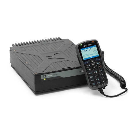
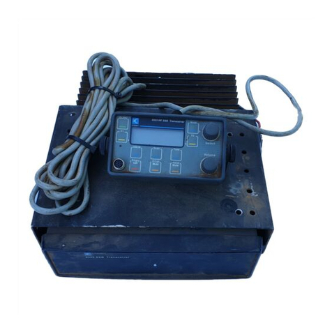
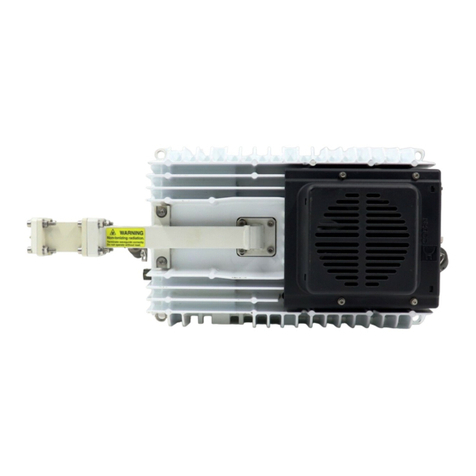
Codan 5700 series User manual

SATELLITE COMMUNICATIONS
REFERENCE MANUAL
C-Band Transceiver
5700 series

No part of this manual may be reproduced, transcribed, translated into any language
or transmitted in any form whatsoever without the prior written consent of Codan
Limited.
© Copyright 1996 Codan Limited
Codan part number 15-40141 Issue 3, March 2001
Windows®is a registered trademark of Microsoft Corporation
The Certification Body of the Russian Federation State Committee of
Communications and Information Technology confirms that the C-Band Transceiver
5700 series conforms to the technical specifications of Russian Interconnected
Communication System.
No OC/1-CC-249

C-Band Transceiver 5700 series Reference Manual i
CODAN
Table of contents
1 About this manual
Standards and icons . . . . . . . . . . . . . . . . . . . . . . . . . . . . . . . . . . . . . . . . . . . . . . . . . . . . . . . . . . . . . 1-2
Definitions . . . . . . . . . . . . . . . . . . . . . . . . . . . . . . . . . . . . . . . . . . . . . . . . . . . . . . . . . . . . . . . . . . . . 1-3
Acronyms and abbreviations . . . . . . . . . . . . . . . . . . . . . . . . . . . . . . . . . . . . . . . . . . . . . . . . . . .1-3
Glossary . . . . . . . . . . . . . . . . . . . . . . . . . . . . . . . . . . . . . . . . . . . . . . . . . . . . . . . . . . . . . . . . . . .1-5
Units . . . . . . . . . . . . . . . . . . . . . . . . . . . . . . . . . . . . . . . . . . . . . . . . . . . . . . . . . . . . . . . . . . . . . . 1-6
Unit multipliers . . . . . . . . . . . . . . . . . . . . . . . . . . . . . . . . . . . . . . . . . . . . . . . . . . . . . . . . . . . . . . 1-6
About this issue . . . . . . . . . . . . . . . . . . . . . . . . . . . . . . . . . . . . . . . . . . . . . . . . . . . . . . . . . . . . . . . .1-7
Associated documents . . . . . . . . . . . . . . . . . . . . . . . . . . . . . . . . . . . . . . . . . . . . . . . . . . . . . . . . . 1-7
2 C-Band transceiver compliance
Electromagnetic Compatibility and safety notices . . . . . . . . . . . . . . . . . . . . . . . . . . . . . . . . . . . . .2-2
Complying with the European Electromagnetic Compatibility Directive . . . . . . . . . . . . . . . . . 2-2
Complying with the European Low Voltage Directive . . . . . . . . . . . . . . . . . . . . . . . . . . . . . . . 2-3
3 Overview
Introduction to the C-Band Transceiver 5700 series . . . . . . . . . . . . . . . . . . . . . . . . . . . . . . . . . . . . 3-2
Transceiver control and monitoring . . . . . . . . . . . . . . . . . . . . . . . . . . . . . . . . . . . . . . . . . . . . . . . . 3-3
Control panel of the converter . . . . . . . . . . . . . . . . . . . . . . . . . . . . . . . . . . . . . . . . . . . . . . . . . . . . .3-4
Converter options . . . . . . . . . . . . . . . . . . . . . . . . . . . . . . . . . . . . . . . . . . . . . . . . . . . . . . . . . . . . . . 3-7
Frequency band options . . . . . . . . . . . . . . . . . . . . . . . . . . . . . . . . . . . . . . . . . . . . . . . . . . . . . . . 3-7
Bandwidth options . . . . . . . . . . . . . . . . . . . . . . . . . . . . . . . . . . . . . . . . . . . . . . . . . . . . . . . . . . . 3-7
Synthesiser options . . . . . . . . . . . . . . . . . . . . . . . . . . . . . . . . . . . . . . . . . . . . . . . . . . . . . . . . . . .3-8
Solid state power amplifier options . . . . . . . . . . . . . . . . . . . . . . . . . . . . . . . . . . . . . . . . . . . . . . . . . 3-9
Frequency band options . . . . . . . . . . . . . . . . . . . . . . . . . . . . . . . . . . . . . . . . . . . . . . . . . . . . . . . 3-9
Output options . . . . . . . . . . . . . . . . . . . . . . . . . . . . . . . . . . . . . . . . . . . . . . . . . . . . . . . . . . . . . . .3-9
Monitor port option . . . . . . . . . . . . . . . . . . . . . . . . . . . . . . . . . . . . . . . . . . . . . . . . . . . . . . . . . . .3-9
Transceiver configurations . . . . . . . . . . . . . . . . . . . . . . . . . . . . . . . . . . . . . . . . . . . . . . . . . . . . . .3-10
Outdoor modules . . . . . . . . . . . . . . . . . . . . . . . . . . . . . . . . . . . . . . . . . . . . . . . . . . . . . . . . . . . . . .3-13
Converter module . . . . . . . . . . . . . . . . . . . . . . . . . . . . . . . . . . . . . . . . . . . . . . . . . . . . . . . . . . .3-13
Solid state power amplifier . . . . . . . . . . . . . . . . . . . . . . . . . . . . . . . . . . . . . . . . . . . . . . . . . . . . 3-14
Low noise amplifier . . . . . . . . . . . . . . . . . . . . . . . . . . . . . . . . . . . . . . . . . . . . . . . . . . . . . . . . .3-14
Transmit reject filter . . . . . . . . . . . . . . . . . . . . . . . . . . . . . . . . . . . . . . . . . . . . . . . . . . . . . . . . .3-14
Power supply unit . . . . . . . . . . . . . . . . . . . . . . . . . . . . . . . . . . . . . . . . . . . . . . . . . . . . . . . . . . . 3-14
Accessories . . . . . . . . . . . . . . . . . . . . . . . . . . . . . . . . . . . . . . . . . . . . . . . . . . . . . . . . . . . . . . . . . . 3-15

Table of contents
ii C-Band Transceiver 5700 series Reference Manual
4 Specifications
Transmit section . . . . . . . . . . . . . . . . . . . . . . . . . . . . . . . . . . . . . . . . . . . . . . . . . . . . . . . . . . . . . . . 4-2
Receive section (excluding LNA) . . . . . . . . . . . . . . . . . . . . . . . . . . . . . . . . . . . . . . . . . . . . . . . . . 4-5
Low noise amplifier . . . . . . . . . . . . . . . . . . . . . . . . . . . . . . . . . . . . . . . . . . . . . . . . . . . . . . . . . . . . 4-7
Transmit reject filter . . . . . . . . . . . . . . . . . . . . . . . . . . . . . . . . . . . . . . . . . . . . . . . . . . . . . . . . . . . . 4-8
General . . . . . . . . . . . . . . . . . . . . . . . . . . . . . . . . . . . . . . . . . . . . . . . . . . . . . . . . . . . . . . . . . . . . . . 4-9
Environmental . . . . . . . . . . . . . . . . . . . . . . . . . . . . . . . . . . . . . . . . . . . . . . . . . . . . . . . . . . . . . . . 4-13
Physical . . . . . . . . . . . . . . . . . . . . . . . . . . . . . . . . . . . . . . . . . . . . . . . . . . . . . . . . . . . . . . . . . . . . . 4-14
5 How the transceiver works
Converter module . . . . . . . . . . . . . . . . . . . . . . . . . . . . . . . . . . . . . . . . . . . . . . . . . . . . . . . . . . . . . . 5-2
Up converter . . . . . . . . . . . . . . . . . . . . . . . . . . . . . . . . . . . . . . . . . . . . . . . . . . . . . . . . . . . . . . . 5-2
Down converter . . . . . . . . . . . . . . . . . . . . . . . . . . . . . . . . . . . . . . . . . . . . . . . . . . . . . . . . . . . . . 5-2
Synthesisers . . . . . . . . . . . . . . . . . . . . . . . . . . . . . . . . . . . . . . . . . . . . . . . . . . . . . . . . . . . . . . . . 5-3
Control and fault detection . . . . . . . . . . . . . . . . . . . . . . . . . . . . . . . . . . . . . . . . . . . . . . . . . . . . 5-3
Solid state power amplifier . . . . . . . . . . . . . . . . . . . . . . . . . . . . . . . . . . . . . . . . . . . . . . . . . . . . . . . 5-4
Low noise amplifier . . . . . . . . . . . . . . . . . . . . . . . . . . . . . . . . . . . . . . . . . . . . . . . . . . . . . . . . . . . . 5-5
Transmit reject filter . . . . . . . . . . . . . . . . . . . . . . . . . . . . . . . . . . . . . . . . . . . . . . . . . . . . . . . . . . . . 5-6
Power supply unit . . . . . . . . . . . . . . . . . . . . . . . . . . . . . . . . . . . . . . . . . . . . . . . . . . . . . . . . . . . . . . 5-7
6 Installation
Unpacking the equipment . . . . . . . . . . . . . . . . . . . . . . . . . . . . . . . . . . . . . . . . . . . . . . . . . . . . . . . . 6-2
Installing the outdoor equipment . . . . . . . . . . . . . . . . . . . . . . . . . . . . . . . . . . . . . . . . . . . . . . . . . . 6-4
Converter module . . . . . . . . . . . . . . . . . . . . . . . . . . . . . . . . . . . . . . . . . . . . . . . . . . . . . . . . . . . 6-4
Solid state power amplifier . . . . . . . . . . . . . . . . . . . . . . . . . . . . . . . . . . . . . . . . . . . . . . . . . . . . 6-5
Low noise amplifier and transmit reject filter . . . . . . . . . . . . . . . . . . . . . . . . . . . . . . . . . . . . . . 6-6
Power supply unit . . . . . . . . . . . . . . . . . . . . . . . . . . . . . . . . . . . . . . . . . . . . . . . . . . . . . . . . . . . 6-7
Grounding recommendations . . . . . . . . . . . . . . . . . . . . . . . . . . . . . . . . . . . . . . . . . . . . . . . . . . . . . 6-9
Welding precautions . . . . . . . . . . . . . . . . . . . . . . . . . . . . . . . . . . . . . . . . . . . . . . . . . . . . . . . . . . . 6-10
Serial interface . . . . . . . . . . . . . . . . . . . . . . . . . . . . . . . . . . . . . . . . . . . . . . . . . . . . . . . . . . . . . . . 6-11
RS232 interface . . . . . . . . . . . . . . . . . . . . . . . . . . . . . . . . . . . . . . . . . . . . . . . . . . . . . . . . . . . . 6-12
RS422 interface . . . . . . . . . . . . . . . . . . . . . . . . . . . . . . . . . . . . . . . . . . . . . . . . . . . . . . . . . . . . 6-12
Monitor and control interface . . . . . . . . . . . . . . . . . . . . . . . . . . . . . . . . . . . . . . . . . . . . . . . . . . . . 6-14
Low noise amplifier interface . . . . . . . . . . . . . . . . . . . . . . . . . . . . . . . . . . . . . . . . . . . . . . . . . . . . 6-17
Cables . . . . . . . . . . . . . . . . . . . . . . . . . . . . . . . . . . . . . . . . . . . . . . . . . . . . . . . . . . . . . . . . . . . . . . 6-18
Cable fabrication . . . . . . . . . . . . . . . . . . . . . . . . . . . . . . . . . . . . . . . . . . . . . . . . . . . . . . . . . . . 6-18
Cable installation . . . . . . . . . . . . . . . . . . . . . . . . . . . . . . . . . . . . . . . . . . . . . . . . . . . . . . . . . . . 6-19

Table of contents
C-Band Transceiver 5700 series Reference Manual iii
7 Setting up the transceiver
Setting the converter option switches . . . . . . . . . . . . . . . . . . . . . . . . . . . . . . . . . . . . . . . . . . . . . . . 7-2
Selecting mains or battery operation . . . . . . . . . . . . . . . . . . . . . . . . . . . . . . . . . . . . . . . . . . . . .7-3
Selecting the voltage at the RF connector . . . . . . . . . . . . . . . . . . . . . . . . . . . . . . . . . . . . . . . . . 7-4
Setting serial interface parameters . . . . . . . . . . . . . . . . . . . . . . . . . . . . . . . . . . . . . . . . . . . . . . . 7-5
Switching on the transceiver . . . . . . . . . . . . . . . . . . . . . . . . . . . . . . . . . . . . . . . . . . . . . . . . . . . . . 7-10
DC supply configuration . . . . . . . . . . . . . . . . . . . . . . . . . . . . . . . . . . . . . . . . . . . . . . . . . . . . . . 7-10
AC supply configuration with a power supply unit . . . . . . . . . . . . . . . . . . . . . . . . . . . . . . . . .7-11
Serial interface control during setup . . . . . . . . . . . . . . . . . . . . . . . . . . . . . . . . . . . . . . . . . . . . . . . 7-13
Temporary interface connection . . . . . . . . . . . . . . . . . . . . . . . . . . . . . . . . . . . . . . . . . . . . . . . . 7-13
HyperTerminal© . . . . . . . . . . . . . . . . . . . . . . . . . . . . . . . . . . . . . . . . . . . . . . . . . . . . . . . . . . . . 7-14
Checking the connection between the terminal and transceiver . . . . . . . . . . . . . . . . . . . . . . . . 7-17
Setting converter parameters . . . . . . . . . . . . . . . . . . . . . . . . . . . . . . . . . . . . . . . . . . . . . . . . . . . . .7-18
Frequency . . . . . . . . . . . . . . . . . . . . . . . . . . . . . . . . . . . . . . . . . . . . . . . . . . . . . . . . . . . . . . . . .7-18
SSPA control mode . . . . . . . . . . . . . . . . . . . . . . . . . . . . . . . . . . . . . . . . . . . . . . . . . . . . . . . . . . 7-19
Fault enables . . . . . . . . . . . . . . . . . . . . . . . . . . . . . . . . . . . . . . . . . . . . . . . . . . . . . . . . . . . . . . .7-19
Converter temperature compensation type . . . . . . . . . . . . . . . . . . . . . . . . . . . . . . . . . . . . . . . . 7-20
SSPA temperature compensation type . . . . . . . . . . . . . . . . . . . . . . . . . . . . . . . . . . . . . . . . . . .7-20
Cable compensation . . . . . . . . . . . . . . . . . . . . . . . . . . . . . . . . . . . . . . . . . . . . . . . . . . . . . . . . . 7-21
Intermediate frequency . . . . . . . . . . . . . . . . . . . . . . . . . . . . . . . . . . . . . . . . . . . . . . . . . . . . . . . 7-24
IF impedance . . . . . . . . . . . . . . . . . . . . . . . . . . . . . . . . . . . . . . . . . . . . . . . . . . . . . . . . . . . . . . . 7-24
Reference oscillator override . . . . . . . . . . . . . . . . . . . . . . . . . . . . . . . . . . . . . . . . . . . . . . . . . . 7-24
Aligning the antenna . . . . . . . . . . . . . . . . . . . . . . . . . . . . . . . . . . . . . . . . . . . . . . . . . . . . . . . . . . . 7-25
Setting the transmit attenuation . . . . . . . . . . . . . . . . . . . . . . . . . . . . . . . . . . . . . . . . . . . . . . . . . . .7-26
Setting the receive attenuation . . . . . . . . . . . . . . . . . . . . . . . . . . . . . . . . . . . . . . . . . . . . . . . . . . . .7-27
8 Operating the transceiver
Switching on the transceiver . . . . . . . . . . . . . . . . . . . . . . . . . . . . . . . . . . . . . . . . . . . . . . . . . . . . . . 8-2
DC supply configuration . . . . . . . . . . . . . . . . . . . . . . . . . . . . . . . . . . . . . . . . . . . . . . . . . . . . . . . 8-2
AC supply configuration with a power supply unit . . . . . . . . . . . . . . . . . . . . . . . . . . . . . . . . . .8-3
Power control . . . . . . . . . . . . . . . . . . . . . . . . . . . . . . . . . . . . . . . . . . . . . . . . . . . . . . . . . . . . . . . . . . 8-5
Standby mode . . . . . . . . . . . . . . . . . . . . . . . . . . . . . . . . . . . . . . . . . . . . . . . . . . . . . . . . . . . . . . . 8-5
Operating mode . . . . . . . . . . . . . . . . . . . . . . . . . . . . . . . . . . . . . . . . . . . . . . . . . . . . . . . . . . . . . . 8-6
Warm-up operation . . . . . . . . . . . . . . . . . . . . . . . . . . . . . . . . . . . . . . . . . . . . . . . . . . . . . . . . . . . 8-6
LED indicators . . . . . . . . . . . . . . . . . . . . . . . . . . . . . . . . . . . . . . . . . . . . . . . . . . . . . . . . . . . . . . . . . 8-7
Low noise amplifier operation . . . . . . . . . . . . . . . . . . . . . . . . . . . . . . . . . . . . . . . . . . . . . . . . . . . . . 8-8
Activating/inhibiting the solid state power amplifier . . . . . . . . . . . . . . . . . . . . . . . . . . . . . . . . . . . 8-9
Fan operation . . . . . . . . . . . . . . . . . . . . . . . . . . . . . . . . . . . . . . . . . . . . . . . . . . . . . . . . . . . . . . . . . 8-11
Serial interface monitor and control . . . . . . . . . . . . . . . . . . . . . . . . . . . . . . . . . . . . . . . . . . . . . . . 8-12

Table of contents
iv C-Band Transceiver 5700 series Reference Manual
Protocol formats . . . . . . . . . . . . . . . . . . . . . . . . . . . . . . . . . . . . . . . . . . . . . . . . . . . . . . . . . . . . . . 8-13
ASCII protocol . . . . . . . . . . . . . . . . . . . . . . . . . . . . . . . . . . . . . . . . . . . . . . . . . . . . . . . . . . . . . 8-13
Packet protocol . . . . . . . . . . . . . . . . . . . . . . . . . . . . . . . . . . . . . . . . . . . . . . . . . . . . . . . . . . . . 8-14
Operating commands . . . . . . . . . . . . . . . . . . . . . . . . . . . . . . . . . . . . . . . . . . . . . . . . . . . . . . . . . . 8-19
Help commands . . . . . . . . . . . . . . . . . . . . . . . . . . . . . . . . . . . . . . . . . . . . . . . . . . . . . . . . . . . . 8-19
View commands . . . . . . . . . . . . . . . . . . . . . . . . . . . . . . . . . . . . . . . . . . . . . . . . . . . . . . . . . . . 8-23
Control commands . . . . . . . . . . . . . . . . . . . . . . . . . . . . . . . . . . . . . . . . . . . . . . . . . . . . . . . . . . 8-27
Set parameter commands . . . . . . . . . . . . . . . . . . . . . . . . . . . . . . . . . . . . . . . . . . . . . . . . . . . . . 8-29
Fault enable commands . . . . . . . . . . . . . . . . . . . . . . . . . . . . . . . . . . . . . . . . . . . . . . . . . . . . . . 8-35
Logging commands . . . . . . . . . . . . . . . . . . . . . . . . . . . . . . . . . . . . . . . . . . . . . . . . . . . . . . . . . 8-36
Output parameter commands . . . . . . . . . . . . . . . . . . . . . . . . . . . . . . . . . . . . . . . . . . . . . . . . . . 8-38
9 Maintenance and fault finding
Precautions . . . . . . . . . . . . . . . . . . . . . . . . . . . . . . . . . . . . . . . . . . . . . . . . . . . . . . . . . . . . . . . . . . . 9-2
DC supply . . . . . . . . . . . . . . . . . . . . . . . . . . . . . . . . . . . . . . . . . . . . . . . . . . . . . . . . . . . . . . . . . 9-2
Connections to power supplies . . . . . . . . . . . . . . . . . . . . . . . . . . . . . . . . . . . . . . . . . . . . . . . . . 9-2
Non user-serviceable modules . . . . . . . . . . . . . . . . . . . . . . . . . . . . . . . . . . . . . . . . . . . . . . . . . . 9-2
Maintaining the solid state power amplifier fan . . . . . . . . . . . . . . . . . . . . . . . . . . . . . . . . . . . . . . . 9-3
Checking the reference oscillator frequency . . . . . . . . . . . . . . . . . . . . . . . . . . . . . . . . . . . . . . . . . 9-4
Remote measurement . . . . . . . . . . . . . . . . . . . . . . . . . . . . . . . . . . . . . . . . . . . . . . . . . . . . . . . . . 9-4
Local measurement . . . . . . . . . . . . . . . . . . . . . . . . . . . . . . . . . . . . . . . . . . . . . . . . . . . . . . . . . . 9-4
Adjusting the reference oscillator frequency . . . . . . . . . . . . . . . . . . . . . . . . . . . . . . . . . . . . . . . 9-5
Replacing fuses . . . . . . . . . . . . . . . . . . . . . . . . . . . . . . . . . . . . . . . . . . . . . . . . . . . . . . . . . . . . . . . . 9-7
Converter fuse . . . . . . . . . . . . . . . . . . . . . . . . . . . . . . . . . . . . . . . . . . . . . . . . . . . . . . . . . . . . . . 9-7
Power supply unit fuse . . . . . . . . . . . . . . . . . . . . . . . . . . . . . . . . . . . . . . . . . . . . . . . . . . . . . . . . 9-8
Fault finding . . . . . . . . . . . . . . . . . . . . . . . . . . . . . . . . . . . . . . . . . . . . . . . . . . . . . . . . . . . . . . . . . . 9-9
If technical assistance is required... . . . . . . . . . . . . . . . . . . . . . . . . . . . . . . . . . . . . . . . . . . . . . . 9-9
Using the fault finding flow charts . . . . . . . . . . . . . . . . . . . . . . . . . . . . . . . . . . . . . . . . . . . . . 9-10
Test procedures . . . . . . . . . . . . . . . . . . . . . . . . . . . . . . . . . . . . . . . . . . . . . . . . . . . . . . . . . . . . . . . 9-24
10 Drawings

Table of contents
C-Band Transceiver 5700 series Reference Manual v
Appendix A—Summary of commands
Help commands . . . . . . . . . . . . . . . . . . . . . . . . . . . . . . . . . . . . . . . . . . . . . . . . . . . . . . . . . . . . . . . A-2
View commands . . . . . . . . . . . . . . . . . . . . . . . . . . . . . . . . . . . . . . . . . . . . . . . . . . . . . . . . . . . . . . A-3
Control commands . . . . . . . . . . . . . . . . . . . . . . . . . . . . . . . . . . . . . . . . . . . . . . . . . . . . . . . . . . . . . A-4
Set parameter commands . . . . . . . . . . . . . . . . . . . . . . . . . . . . . . . . . . . . . . . . . . . . . . . . . . . . . . . . A-5
Fault enable commands . . . . . . . . . . . . . . . . . . . . . . . . . . . . . . . . . . . . . . . . . . . . . . . . . . . . . . . . . A-7
Logging commands . . . . . . . . . . . . . . . . . . . . . . . . . . . . . . . . . . . . . . . . . . . . . . . . . . . . . . . . . . . . A-8
Output parameter commands . . . . . . . . . . . . . . . . . . . . . . . . . . . . . . . . . . . . . . . . . . . . . . . . . . . . . A-9
Index

Table of contents
vi C-Band Transceiver 5700 series Reference Manual
This page has been left blank intentionally.

C-Band Transceiver 5700 series Reference Manual vii
CODAN
List of figures
Figure 3-1: Control panel of the converter . . . . . . . . . . . . . . . . . . . . . . . . . . . . . . . . . . . . . . . . .3-4
Figure 3-2: DC supply configuration. . . . . . . . . . . . . . . . . . . . . . . . . . . . . . . . . . . . . . . . . . . . .3-11
Figure 3-3: AC supply configuration. . . . . . . . . . . . . . . . . . . . . . . . . . . . . . . . . . . . . . . . . . . . .3-12
Figure 6-1: Typical transceiver installation. . . . . . . . . . . . . . . . . . . . . . . . . . . . . . . . . . . . . . . . .6-3
Figure 6-2: LNA +15V switch position. . . . . . . . . . . . . . . . . . . . . . . . . . . . . . . . . . . . . . . . . . . . 6-7
Figure 6-3: Monitor/Control connector interface of the converter . . . . . . . . . . . . . . . . . . . . . .6-16
Figure 6-4: LNA DC/ALARM connector interface of the converter . . . . . . . . . . . . . . . . . . . . 6-17
Figure 7-1: Mains/Battery switch position . . . . . . . . . . . . . . . . . . . . . . . . . . . . . . . . . . . . . . . . . 7-3
Figure 7-2: LNA +15V switch position. . . . . . . . . . . . . . . . . . . . . . . . . . . . . . . . . . . . . . . . . . . . 7-4
Figure 7-3: Recommended serial interface option switch settings . . . . . . . . . . . . . . . . . . . . . . . 7-5
Figure 9-1: Reference oscillator adjustment . . . . . . . . . . . . . . . . . . . . . . . . . . . . . . . . . . . . . . . .9-5
Figure 9-2: Location of the fuse on the converter . . . . . . . . . . . . . . . . . . . . . . . . . . . . . . . . . . . .9-7
Figure 9-3: Main fault diagnosis chart. . . . . . . . . . . . . . . . . . . . . . . . . . . . . . . . . . . . . . . . . . . .9-12
Figure 9-4: DC power supply system fault diagnosis chart. . . . . . . . . . . . . . . . . . . . . . . . . . . . 9-13
Figure 9-5: AC power supply system fault diagnosis chart. . . . . . . . . . . . . . . . . . . . . . . . . . . . 9-14
Figure 9-6: SSPA fault diagnosis chart . . . . . . . . . . . . . . . . . . . . . . . . . . . . . . . . . . . . . . . . . . . 9-15
Figure 9-7a: Fan fault diagnosis chart . . . . . . . . . . . . . . . . . . . . . . . . . . . . . . . . . . . . . . . . . . . . 9-16
Figure 9-7b: Fan fault diagnosis chart continued . . . . . . . . . . . . . . . . . . . . . . . . . . . . . . . . . . . . 9-17
Figure 9-8a: Temperature fault diagnosis chart . . . . . . . . . . . . . . . . . . . . . . . . . . . . . . . . . . . . .9-18
Figure 9-8b: Temperature fault diagnosis chart continued . . . . . . . . . . . . . . . . . . . . . . . . . . . . . 9-19
Figure 9-9a: LNA fault diagnosis chart A . . . . . . . . . . . . . . . . . . . . . . . . . . . . . . . . . . . . . . . . . 9-20
Figure 9-9b: LNA fault diagnosis chart A continued . . . . . . . . . . . . . . . . . . . . . . . . . . . . . . . . .9-21
Figure 9-10a: LNA fault diagnosis chart B . . . . . . . . . . . . . . . . . . . . . . . . . . . . . . . . . . . . . . . . .9-22
Figure 9-10b: LNA fault diagnosis chart B continued . . . . . . . . . . . . . . . . . . . . . . . . . . . . . . . . .9-23

List of figures
viii C-Band Transceiver 5700 series Reference Manual
This page has been left blank intentionally.

C-Band Transceiver 5700 series Reference Manual ix
CODAN
List of tables
Table 2-1: Ground symbols . . . . . . . . . . . . . . . . . . . . . . . . . . . . . . . . . . . . . . . . . . . . . . . . . . . .2-4
Table 3-1: Frequency band options for the converter . . . . . . . . . . . . . . . . . . . . . . . . . . . . . . . .3-7
Table 3-2: Frequency band options for the SSPA . . . . . . . . . . . . . . . . . . . . . . . . . . . . . . . . . . . 3-9
Table 6-1: Interconnection of standard cables . . . . . . . . . . . . . . . . . . . . . . . . . . . . . . . . . . . . . 6-21
Table 7-1: Option switches . . . . . . . . . . . . . . . . . . . . . . . . . . . . . . . . . . . . . . . . . . . . . . . . . . . . 7-2
Table 7-2: Position of DIP option switches for serial interface operating mode . . . . . . . . . . . 7-6
Table 7-3: Position of DIP option switches for general serial interface parameters . . . . . . . . . 7-7
Table 7-4: Position of DIP option switches for serial interface RS422 . . . . . . . . . . . . . . . . . . 7-8
Table 7-5: Position of DIP option switches for serial interface packet address . . . . . . . . . . . . 7-9
Table 7-6: Available frequency ranges . . . . . . . . . . . . . . . . . . . . . . . . . . . . . . . . . . . . . . . . . .7-18
Table 7-7: Fault enable commands . . . . . . . . . . . . . . . . . . . . . . . . . . . . . . . . . . . . . . . . . . . . . 7-19
Table 7-8: Standard SSPA type . . . . . . . . . . . . . . . . . . . . . . . . . . . . . . . . . . . . . . . . . . . . . . . . 7-20
Table 7-9: Cable compensation settings (70 MHz IF) . . . . . . . . . . . . . . . . . . . . . . . . . . . . . . 7-22
Table 7-10: Cable compensation settings (140 MHz IF) . . . . . . . . . . . . . . . . . . . . . . . . . . . . . 7-23
Table 8-1: LED indications . . . . . . . . . . . . . . . . . . . . . . . . . . . . . . . . . . . . . . . . . . . . . . . . . . . .8-7
Table 8-2: Error responses . . . . . . . . . . . . . . . . . . . . . . . . . . . . . . . . . . . . . . . . . . . . . . . . . . . .8-18
Table 8-3: Transmit frequency ranges . . . . . . . . . . . . . . . . . . . . . . . . . . . . . . . . . . . . . . . . . . . 8-32
Table 8-4: Receive frequency ranges . . . . . . . . . . . . . . . . . . . . . . . . . . . . . . . . . . . . . . . . . . . 8-32
Table 9-1: Power supply fuses . . . . . . . . . . . . . . . . . . . . . . . . . . . . . . . . . . . . . . . . . . . . . . . . . 9-8
Table 9-2: Customer service contact numbers . . . . . . . . . . . . . . . . . . . . . . . . . . . . . . . . . . . . . 9-9
Table 9-3: Test A . . . . . . . . . . . . . . . . . . . . . . . . . . . . . . . . . . . . . . . . . . . . . . . . . . . . . . . . . . . 9-24
Table 9-4: Test B . . . . . . . . . . . . . . . . . . . . . . . . . . . . . . . . . . . . . . . . . . . . . . . . . . . . . . . . . . . 9-24
Table 9-5: Test C . . . . . . . . . . . . . . . . . . . . . . . . . . . . . . . . . . . . . . . . . . . . . . . . . . . . . . . . . . . 9-24
Table 9-6: Test D . . . . . . . . . . . . . . . . . . . . . . . . . . . . . . . . . . . . . . . . . . . . . . . . . . . . . . . . . . . 9-25
Table 9-7: Test E . . . . . . . . . . . . . . . . . . . . . . . . . . . . . . . . . . . . . . . . . . . . . . . . . . . . . . . . . . .9-25
Table 9-8: Test F . . . . . . . . . . . . . . . . . . . . . . . . . . . . . . . . . . . . . . . . . . . . . . . . . . . . . . . . . . .9-25
Table 9-9: Test G . . . . . . . . . . . . . . . . . . . . . . . . . . . . . . . . . . . . . . . . . . . . . . . . . . . . . . . . . . . 9-26
Table 9-10: Test H . . . . . . . . . . . . . . . . . . . . . . . . . . . . . . . . . . . . . . . . . . . . . . . . . . . . . . . . . . . 9-26
Table 9-11: Test J . . . . . . . . . . . . . . . . . . . . . . . . . . . . . . . . . . . . . . . . . . . . . . . . . . . . . . . . . . . 9-26
Table 9-12: Test K . . . . . . . . . . . . . . . . . . . . . . . . . . . . . . . . . . . . . . . . . . . . . . . . . . . . . . . . . . . 9-27
Table A-1: Help commands . . . . . . . . . . . . . . . . . . . . . . . . . . . . . . . . . . . . . . . . . . . . . . . . . . . A-2
Table A-2: View commands . . . . . . . . . . . . . . . . . . . . . . . . . . . . . . . . . . . . . . . . . . . . . . . . . . . A-3
Table A-3: Control commands . . . . . . . . . . . . . . . . . . . . . . . . . . . . . . . . . . . . . . . . . . . . . . . . . A-4
Table A-4: Set parameter commands . . . . . . . . . . . . . . . . . . . . . . . . . . . . . . . . . . . . . . . . . . . . A-5
Table A-5: Fault enable commands . . . . . . . . . . . . . . . . . . . . . . . . . . . . . . . . . . . . . . . . . . . . . A-7

List of tables
xC-Band Transceiver 5700 series Reference Manual
Table A-6: Logging commands . . . . . . . . . . . . . . . . . . . . . . . . . . . . . . . . . . . . . . . . . . . . . . . . . A-8
Table A-7: Output parameter commands . . . . . . . . . . . . . . . . . . . . . . . . . . . . . . . . . . . . . . . . . A-9

C-Band Transceiver 5700 series Reference Manual 1-1
CODAN
1 About this manual
This reference manual is for installation technicians and operators of the C-Band
Transceiver 5700 series.
This manual has ten chapters and one appendix:
Chapter 1 About this manual—lists all terms, abbreviations and units used in this
guide
Chapter 2 C-Band transceiver compliance—describes how to ensure compliance of
the C-Band transceiver is maintained
Chapter 3 Overview—general description of the transceiver
Chapter 4 Specifications—specifications for all the transceiver modules
Chapter 5 How the transceiver works—brief technical description of the transceiver
Chapter 6 Installation—how to unpack and install the transceiver
Chapter 7 Setting up the transceiver—how to set up the transceiver ready for
operation
Chapter 8 Operating the transceiver—operating procedures and serial interface
commands
Chapter 9 Maintenance and fault finding
Chapter 10 Drawings
Appendix A Summary of commands—summary of the commands described in
Chapter 8, Operating the transceiver
An index can be found at the end of the manual.

About this manual
1-2 C-Band Transceiver 5700 series Reference Manual
Standards and icons
The following standards and icons are used in this manual:
This typeface Means
BOLD a button, switch, light emitting diode or connector, or displayed text
Bold a command that you enter or keyboard key that you press
Courier a segment of text that is taken directly from a computer screen
Italics a cross-reference or text requiring emphasis
UPPER CASE a switch position
This icon Means
a warning—your actions may cause harm to yourself or the equipment
a caution—proceed with caution as your actions may lead to loss of
data, privacy or signal quality
a note—the text provided next to this icon may be of interest to you
qa step to follow

About this manual
C-Band Transceiver 5700 series Reference Manual 1-3
Definitions
Acronyms and abbreviations
This term Means...
AC alternating current
AGC automatic gain control
ASCII American standard code for information interchange
AWG American wire gauge
BW bandwidth
CTS clear to send
DC direct current
DCE data communication equipment
DIP dual inline package
EMC electromagnetic compatibility
FET field effect transistor
GaAs Gallium Arsenide
GCP gain compression point
GND ground
G/T gain/temperature
H hexadecimal
H/W hardware
HEMT high electron mobility transistor
HPA high power amplifier
IF intermediate frequency
LED light emitting diode
LNA low noise amplifier
LO local oscillator
LSB least significant bit
MS military specification
MSB most significant bit

About this manual
1-4 C-Band Transceiver 5700 series Reference Manual
NC normally closed
NO normally open
OMT ortho-mode transducer
OPBO output back off
PC personal computer
PLL phase locked loop
PSU power supply unit
RD receive data
RF radio frequency
RTS request to send
Rx receive
SHF super high frequency
SSB single sideband
SSPA solid state power amplifier
TD transmit data
TRF transmit reject filter
TWTA travelling wave tube amplifier
Tx transmit
VSWR voltage standing wave ratio
This term Means...

About this manual
C-Band Transceiver 5700 series Reference Manual 1-5
Glossary
This term Means...
C-band Band of frequencies nominally covering the frequencies generally in
the range 4 GHz to 6 GHz.
Carrier RF signal used to carry information.
Demodulator Device used to extract digital information from a modulated RF
carrier.
Earth station Transmission and reception site for communication by satellite.
Modem Device used to convert digital information to a modulated RF carrier
and to extract digital information from a modulated RF carrier.
Packet protocol Serial communication method using a structured addressable packet of
ASCII characters.
Transceiver Equipment comprising the converter, solid state power amplifier and
low noise amplifier, connecting cables and mounting brackets.
Transponder The equipment on a satellite that receives signals, translates their
frequency, and re-transmits these signals.

About this manual
1-6 C-Band Transceiver 5700 series Reference Manual
Units
Unit multipliers
Measurement Unit Abbreviation
Attenuation decibel dB
Current ampere A
Data rate bits per second bps
Depth millimetre D
Frequency hertz Hz
Height millimetre H
Impedance ohm Ω
Length metre m
Noise temperature Kelvin K
Pressure pascal Pa
Power decibels relative to a carrier dBc
Power decibels relative to 1 mW dBm
Power watt W
Temperature degrees Celsius °C
Voltage volt V
Weight gram g
Width millimetre W
Unit Name Multiplier
m milli 10–3
ddeci10
–1
kkilo10
3
Mmega10
6
Ggiga10
9

About this manual
C-Band Transceiver 5700 series Reference Manual 1-7
About this issue
This is the third issue of the C-Band Transceiver 5700 series Reference Manual.
Associated documents
This manual is one of a series of publications related to the C-Band Transceiver 5700
series. Other associated publications are:
•Hand-Held Controller 5560 User Guide (Codan part number 15-40157)
•Remote Controller 5570 User Guide (Codan part number 15-40158)
•C-Band Transceiver 5700 series Redundancy Switching Equipment Reference
Manual (Codan part number 15-40186-EN)
•C-Band High Power Transceiver 5700 series Reference Manual (Codan part number
15-40176)
•C-Band Solid State Power Amplifier 5760/5712H Reference Manual (Codan part
number 15-40167-EN)

About this manual
1-8 C-Band Transceiver 5700 series Reference Manual
This page has been left blank intentionally.
Table of contents
Other Codan Transceiver manuals

Codan
Codan 9313 Service manual

Codan
Codan HF SSB User manual

Codan
Codan Envoy User manual

Codan
Codan 2110 series User manual

Codan
Codan Envoy 2220 User manual

Codan
Codan X-2 User manual

Codan
Codan 2110 series Assembly instructions

Codan
Codan HF SSB User manual

Codan
Codan Envoy User manual

Codan
Codan 8528 Series User manual

Codan
Codan NGT 2010 RF Operating manual

Codan
Codan 8525 Owner's manual

Codan
Codan NGT AR User manual

Codan
Codan SRx User manual

Codan
Codan Envoy User manual

Codan
Codan 8525B Series Operating manual

Codan
Codan 2110 series User manual

Codan
Codan 8525 Owner's manual

Codan
Codan 2110 series User manual

Codan
Codan Cascade User manual