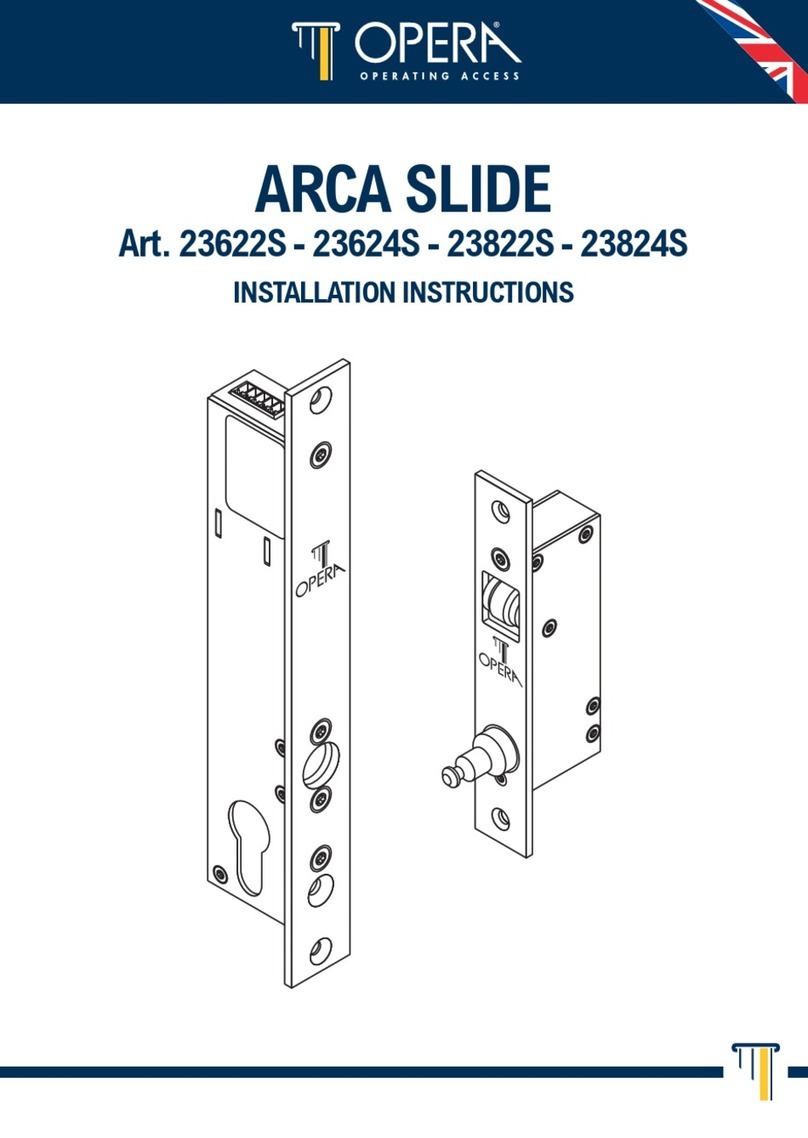
N.B. The plunger beside the latchbolt deadlocks it to protect against manipulation or ‘shimming’. The
strike plate must be accurately installed so that the plunger CANNOT enter the aperture when the door is
closed, even when it is slammed shut.
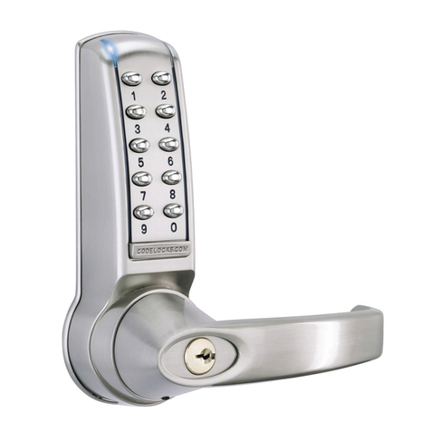
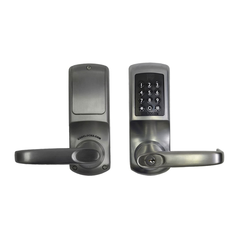
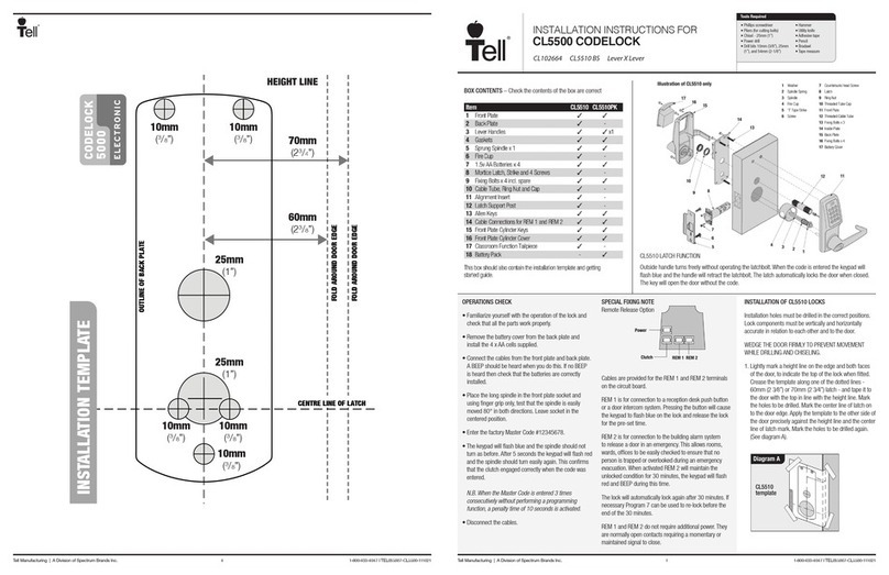
INSTALLATION OF CL5510PK
1. The position of the Codelocks CL5510 front unit on the door is determined by the position of the panic
device.
2. Mark the position of the spindle hole for the panic device on both sides of the door.
3. Place the gasket against the door with the 20mm (⁄”) hole centred over the mark for spindle hole.
Using the gasket as a template mark the 3 x 8mm (⁄”) holes for the through fixing bolts. Repeat on the
other side of the door.
4. Drill the 2 x 20mm (⁄”) holes and the 3 x 8mm (⁄”) holes, drilling from both sides to avoid splintering
out the face of the door. Attach the seal and insert the spindle in the back of the keypad. Offer the lock up
to the door and feed the power cable through the door and connect the battery pack on the inside.
5. Countersink the bottom fixing hole as necessary so that the fixing bolt lies flush with the door face,
underneath the panic device. Now fit the two top fixing bolts. Using the wood screw provided, fit the
battery pack on the inside of the door.
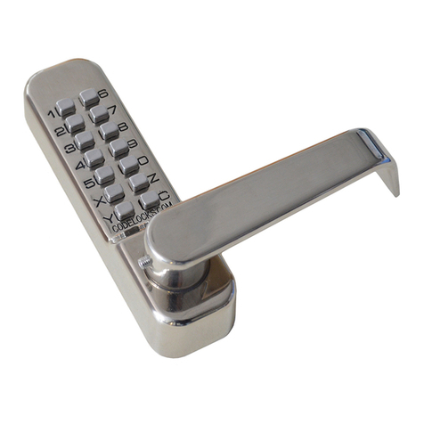
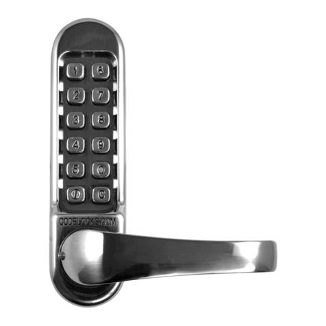
6. Fit the lever handle to the CL5510 front unit and tighten the socket head screw in the handle. Enter the
code of the CL5510 front unit and check that the lever will turn fully.
7. Install the panic device and make sure that the Codelocks front unit will fully retract the latch or bolts.
Please note: the spindle may need to be cut to suit the door thickness and engagement with both
the Codelock and panic device.
II-CL5510-CLINC-V1:0716
© 2018 Codelocks Ltd. All rights reserved.
Keywords: Lock Locks Codelock Codelocks Locker Program Programming Instruction Instruct Help
Support Troubleshoot Troubleshooting Sequence Sequences Install Installation Parameters Settings
Setting CL 5500 CL5500
