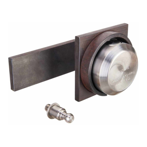
WABCO TSR-2FIXX User manual

MONTAGEANLEITUNG
© 2018 WABCO All rights reserved – 815 980 358 3 Doc-Code 111 Index Edition 07.2018
TÜRVERRIEGELUNG TSR-2FIXX 183 210 000 4
Lieferumfang
1x Montageplatte für die linke
Tür von innen
1x Gehäusekopf 1x große Grundplatte für die
rechte Tür
1x Dummy mit Schraube
1x kleine Grundplatte für die
linke Tür
8x Sechskantmutter
8x Unterlegschreibe
8x Gewindestange M12x120 1x Sicherungsstift mit M20
Muttern
1x Anbau Schablone 3x Schlüssel (kd) 1x Schlüsselkarte
i
i
Bewahren Sie die Schlüsselkarte auf. Sie benötigen die Schlüsselkarte für Nachbestellungen weiterer Schlüssel.
Montage
WARNUNG
Unfallgefahr
Bei der Montage besteht Unfallgefahr durch sich bewegende Fahrzeuge und Fahrzeugteile.
–Sichern Sie das Fahrzeug mit Unterlegkeilen und befestigen Sie bewegliche Fahrzeugteile.
VORSICHT
Quetschgefahr für Finger/Hände
Bei der Montage besteht Quetschgefahr für Finger/Hände.
–Achten Sie darauf, dass Ihre Finger/Hände nicht gequetscht werden.
VORSICHT
Verletzungsgefahr für Füße
Eine herunterfallende Verriegelung kann durch ihr Gewicht zu Verletzungen führen.
–Tragen Sie Sicherheitsschuhe bei der Montage.
i
i
Sichern Sie alle Schrauben und Muttern zusätzlich mit LOCTITE (hochfest).
i
i
Wenn die Grundplatte über das
Türgummi herausragt, schneiden Sie das
Türgummi ein.
183 410 001 0 183 410 006 0
183 410 006 2

MONTAGEANLEITUNG
© 2018 WABCO All rights reserved – 815 980 358 3 Doc-Code 111 Index Edition 07.2018
1. Vorbereitung für die Montage an der linken Tür
– Schneiden Sie die Schablone an der dick gezeichneten Linie gerade auseinander.
– Bringen Sie auf der linken Tür das entsprechende Schablonenteil so weit rechts wie möglich von außen an.
i
i
Achten Sie
darauf, dass auf der Innenseite der Tür keine störenden Objekte sind.
– Schrauben Sie den Dummy auf die kleine Grundplatte.
– Sichern Sie die Schraube zusätzlich mit LOCTITE (hochfest).
– Schrauben Sie die vier Gewindestangen in die Gewindelöcher der kleinen Grundplatte. Sie benötigen nur die äußeren
Gewindelöcher (links und rechts oben, sowie links und rechts unten).
– Sichern Sie die Gewindestangen zusätzlich mit LOCTITE (hochfest).
2. Montage an der linken Tür
Benötigte Teile: Montageplatte; 4 Unterlegscheiben; 4 Sechskantmuttern; kleine Grundplatte mit angeschraubtem Dummy und 4
Gewindestangen. Auf dem angebrachten Schablonenteil sehen Sie insgesamt 6 Bohrlöcher. Sie benötigen nur die äußeren (links
und rechts oben, sowie links und rechts unten).
– Bohren Sie diese vier Bohrlöcher mit einem 5 mm HSS-Bohrer vor.
– Vergrößern Sie die Bohrlöcher mit einem 12,5 mm HSS-Bohrer.
– Entgraten Sie anschließend alle scharfen Kanten.
– Nehmen Sie die Schablone wieder ab.
– Stecken Sie die Gewindestangen (der kleinen Grundplatte) durch die gebohrten Löcher (der Dummy muss auf der linken
Seite sein).
– Setzen Sie die ovalen Öffnungen der Montageplatte von der Innenseite der Tür über die Gewindestangen, so dass die Zunge
über die Tür ragt.
– Legen Sie je eine Unterlegscheibe und eine Mutter auf die Gewindestangen.
– Ziehen Sie die Muttern fest an.
i
i
Achten Sie darauf, die Montageplatte rechtwinklig auszurichten.
– Sichern Sie die Muttern zusätzlich mit LOCTITE (hochfest).
3. Vorbereitung für die Montage an der rechten Tür
i
i
Für die folgenden Montageschritte benötigen Sie eine zweite Person.
– Bringen Sie die Montageplatte in den Container bzw. Laderaum.
– Lassen Sie die Türen von außen richtig schließen.
ÖTüren müssen vollständig geschlosen sein.
– Markieren Sie das M20 Gewinde-Loch der Montageplatte auf der Innentür.
– Öffnen Sie die Türen wieder.
– Bohren Sie in der Mitte der markierten Stelle mit einem 5 mm HSS-Bohrer ein Loch gerade durch die Tür.
– Schließen Sie die Türen von außen.
– Kleben Sie über das gerade gebohrte Loch den rechten Teil der Schablone.
i
i
Die aufgezeichneten Bohrlöcher zeigen
nach rechts, und das aufgezeichnete große Bohrloch muss mittig zentriert über dem gebohrten Loch liegen.
– Erweitern Sie das Bohrloch für den Sicherungsstift (M20):
Bei Containertüren: Erweitern Sie das Loch auf 30 mm mit einem großen Schälbohrer.
Bei LKW-, Auieger- oder Anhänger-Türen: Erweitern Sie das Loch auf 40 mm mit einem großen Schälbohrer.
– Entgraten Sie anschließend alle scharfen Kanten.
i
i
Die unterschiedliche Größe berücksichtigt einen Spielraum für den
Sicherungsstift. Da Container nicht sehr starken Verkantungen bzw. Erschütterungen ausgesetzt werden, wird hier ein
geringerer Spielraum benötigt.
– Markieren Sie mit einem Körner von außen 4 von den 6 kleinen M12 Bohrlöchern (2 oben und 2 unten).
i
i
Achten Sie
darauf, dass auf der Innenseite der Tür keine störenden Objekte sind.
4. Montage an der rechten Tür
Montage der großen Grundplatte:
– Bohren Sie die markierten M12 Bohrlöcher mit einem 5 mm HSS-Bohrer vor.
– Vergrößern Sie die Bohrlöcher mit einem 12,5 mm HSS-Bohrer.

MONTAGEANLEITUNG
© 2018 WABCO All rights reserved – 815 980 358 3 Doc-Code 111 Index Edition 07.2018
– Entgraten Sie anschließend alle scharfen Kanten.
– Schrauben Sie vier Gewindestangen in die entsprechenden Gewindelöcher (wie bei der Schablone benutzt) der großen
Grundplatte.
– Sichern Sie die Gewindestangen zusätzlich mit LOCTITE (hochfest).
– Nehmen Sie die Schablone wieder ab.
– Stecken Sie die Gewindestangen (der großen Grundplatte) durch die gebohrten Löcher (wobei die Aussparung der
Grundplatte nach unten zeigen muss).
– Legen Sie je eine Unterlegscheibe und eine Mutter auf die Gewindestangen.
– Ziehen Sie die Muttern fest an.
i
i
Achten Sie darauf, die Montageplatte rechtwinklig auszurichten.
– Sichern Sie die Muttern zusätzlich mit LOCTITE (hochfest).
Montage des Sicherungsstifts:
– Drehen Sie den Sicherungsstift (von außen nach innen) in das Gewindeloch der Montageplatte.
– Drehen Sie den Sicherungsstift soweit in die Montageplatte hinein, so dass er nur noch ca. 30 mm aus der Bohrung der
Grundplatte herausschaut, wenn die Türen geschlossen sind.
– Sichern Sie den Sicherungsstift noch nicht mit der Mutter.
– Setzen Sie den Gehäusekopf auf den Sicherungsstift.
– Versuchen Sie mit Hilfe der mitgelieferten Schlüssel den Gehäusekopf zu verriegeln (abzuschließen).
i
i
Wenn Sie den Gehäusekopf nicht verriegeln können, ist der Sicherungsstift zu weit in die Montageplatte eingedreht und
muss wieder etwas herausgedreht werden.
i
i
Der Gehäusekopf sollte einen Abstand (Spiel) von 1 bis 2 mm zur großen Grundplatte haben (Türen müssen vollständig
geschlossen sein!). Ist der Abstand größer, muss der Sicherungsstift noch weiter in die Montageplatte gedreht werden. Der
Abstand darf auf keinen Fall größer als 2 mm sein, da sonst der Gehäusekopf mit einem Spezialwerkzeug aufgehebelt werden
könnte. Der Gehäusekopf darf auf keinen Fall stramm an der großen Grundplatte anliegen, da er sich sonst unter Umständen
(Wärme/Kälte/Staub/etc.) nicht mehr öffnen lässt.
– Nehmen Sie den Gehäusekopf vorsichtig wieder ab (damit der Sicherungsstift sich nicht wieder verdreht).
– Öffnen Sie die Tür.
– Drehen Sie die M20 Mutter von hinten auf den Sicherungsstift.
– Ziehen Sie die M20 Mutter fest an, ohne den Sicherungsstift zu verdrehen.
– Sichern Sie die M20 Mutter zusätzlich mit LOCTITE (hochfest).
– Nachdem Sie sich überzeugt haben, dass alles passt, und sich das Schloss ordnungsgemäß verriegeln lässt, kürzen Sie den
Sicherungsstift auf der Innenseite der Tür und entgraten diesen, um Verletzungsgefahren zu vermeiden.
Wartung und Pege
HINWEIS
Beschädigung des Verriegelungsmechanismus
Teon verklebt den Verriegelungsmechanismus.
–Verwenden Sie niemals Teon.
Mechanische Teile: keine Wartung / Pege erforderlich
Zylinder reinigen und pegen: Zum Reinigen verwenden Sie Bremsenreiniger. Danach etwas Leichtöl in das Schlüsselloch
träufeln und mit dem Schlüssel ein paar Mal hin und her drehen.
Geeignete Ölsorten: Nähmaschinen-Öl, Waffen-Öl, dünnüssiges, synthetisches Motoröl.

INSTALLATION INSTRUCTION
© 2018 WABCO All rights reserved – 815 980 358 3 Doc-Code 111 Index Edition 07.2018
DOOR LOCK TSR-2FIXX 183 210 000 4
Scope of supply
1x mounting plate for left door
from the inside
1x housing head 1x large base plate for the
right door
1x dummy with screw
1x small base plate for the left
door
8x hexagon nut
8x washer
8x threaded rod M12x120 1x lock pin with M20 nuts
1x mounting template 3x key (kd) 1x key card
i
i
Keep the key card in a safe place. You need the key card to order additional keys.
Installation
WARNING
Danger of accidents
During assembly there is a risk of accidents due to moving vehicles and vehicle parts.
–Secure the vehicle with chocks and fasten moving vehicle parts.
CAUTION
Risk of crushing ngers/hands
During assembly there is a risk of crushing ngers/hands.
–Make sure that your ngers are not crushed.
CAUTION
Risk of injury for feet
A lock that falls from height can cause injuries due to its weight.
–Wear safety shoes during assembly.
i
i
Additionally secure all screws and nuts with LOCTITE (high strength).
i
i
If the base plate protrudes over the
rubber door seals, cut the door seal.
183 410 001 0 183 410 006 0 183 410 006 2

INSTALLATION INSTRUCTION
© 2018 WABCO All rights reserved – 815 980 358 3 Doc-Code 111 Index Edition 07.2018
1. Preparation for assembly on the left door
– Separate the template by cutting along the thick straight drawn line.
– From the outside, attach the corresponding template section onto the left door as far as possible to the right. Make sure there
are no interfering objects on the door’s inside.
– Screw the dummy onto the small base plate.
– Additionally secure the screw with LOCTITE (high strength).
– Screw the four threaded rods into the threaded holes of the small base plate. You only need the outer threaded holes (left and
right at the top, and left and right at the bottom).
– Additionally secure the threaded rods with LOCTITE (high strength).
2. Assembly on the left door
Required parts: Mounting plate; 4 washers; 4 hexagon nuts; small base plate with dummy screwed on and 4 threaded rods. You
can see a total of 6 bore holes on the attached template section. You only need the outer ones (left and right at the top, and left
and right at the bottom).
– Use a 5 mm HSS drill to pre-drill these four holes.
– Use a 12.5 mm HSS drill to enlarge these holes.
– Then deburr all sharp edges.
– Remove the template again.
– Put the threaded rods (of the small base plate) through the drilled holes (the dummy must on the left side).
– Place the oval openings of the mounting plate over the threaded rods from the inside so that the latch protrudes over the door.
– Place one washer and one nut respectively onto the threaded rods.
– Firmly tighten the nuts.
i
i
Make sure the mounting plate is aligned at a right angle.
– Additionally secure the nuts with LOCTITE (high strength).
3. Preparation for assembly on the right door
i
i
You will need a second person for the following assembly steps.
– Bring the mounting plate into the container or cargo hold.
– Let the doors be properly closed from the outside.
ÖThe doors must be fully closed.
– Mark the M20 threaded hole of the mounting plate on the inside door.
– Open the door again.
– Use a 5 mm HSS drill to drill a straight hole through the door at the centre of the marked point.
– Close the door from the outside.
– Glue the right section of the template over the hole you just drilled.
i
i
The marked bore holes point to the right and the
marked large hole must be lie centred over the middle of the drilled hole.
– Enlarge the bore hole for the lock pin (M20):
With container doors: Use a large quick-helix drill to enlarge the hole to 30 mm.
For truck, semitrailer or trailer doors: Use a large quick-helix drill to enlarge the hole to 40 mm.
– Then deburr all sharp edges.
i
i
The different size takes into account a clearance for the lock pin. Since containers not subjected to intense tilting or impacts,
less clearance is required in this case.
– Use a centre punch to mark 4 of the 6 small M12 bore holes (2 at the top and 2 at the bottom) from the outside.
i
i
Make
sure there are no interfering objects on the door’s inside.

INSTALLATION INSTRUCTION
© 2018 WABCO All rights reserved – 815 980 358 3 Doc-Code 111 Index Edition 07.2018
4. Assembly on the right door
Assembly on the large base plate:
– Use a 5 mm HSS drill to pre-drill marked M12 holes.
– Use a 12.5 mm HSS drill to enlarge these holes.
– Then deburr all sharp edges.
– Screw the four threaded rods into the corresponding threaded holes (as used with the template) of the large base plate.
– Additionally secure the threaded rods with LOCTITE (high strength).
– Remove the template again.
– Put the threaded rods (of the large base plate) through the drilled holes (here the base plate recess must point downwards).
– Place one washer and one nut respectively onto the threaded rods.
– Firmly tighten the nuts.
i
i
Make sure the mounting plate is aligned at a right angle.
– Additionally secure the nuts with LOCTITE (high strength).
Fitting the lock pin:
– Screw the lock pin (from the outside to the inside) into the threaded hole of the mounting plate.
– Screw the lock pin into the mounting plate so that it only protrudes out of the hole of the base plate by around 30 mm when
the doors are closed.
i
i
Do not yet secure the lock pin with the nut.
– Place the housing head onto the lock pin.
– Use the supplied key to try and lock the housing head.
i
i
If you cannot lock the housing head, the lock pin has been screwed too far into the mounting plate und must be screwed
out again a little.
i
i
The housing head should have a distance (clearance) of 1 to 2 mm to the large base plate (doors must be fully closed!). If
the distance is greater, the lock pin must be screwed further into the mounting plate. The distance must never be greater than 2
mm, because otherwise the housing head could be pried open with a special tool. The housing head must never t tight against
the large base plate, because otherwise it may longer be possible to open it under certain circumstances (heat/cold/dust etc.).
– Remove the housing head again with care (to make sure that the lock pin does not turn out of position again).
– Open the door.
– Screw the M20 nut onto the lock pin from the back.
– Firmly tighten the M20 nut without rotating the lock pin out of position.
– Additionally secure the M20 nut with LOCTITE (high strength).
– After you have veried that everything ts and the lock can be properly locked, shorten the lock pin on the door’s inside and
deburr it to avoid any risk of injuries.
Maintenance and care
NOTE
Damage of locking mechanism
Teon clogs the locking mechanism.
–Never use Teon.
Mechanical parts: no maintenance / care required
Cleaning and care of the cylinder: Use brake cleaner for cleaning. Then drip a little light oil into the keyhole and rotate back and
forth a few times with the key.
Suitable oil types: Sewing machine oil, gun oil, low-viscosity synthetic engine oil.
This manual suits for next models
1
Table of contents
Languages:
Other WABCO Door Lock manuals