3
6X-1048B
2740 CAMERA
INSTALLATION AND OPERATION
1.0 GENERAL DESCRIPTION
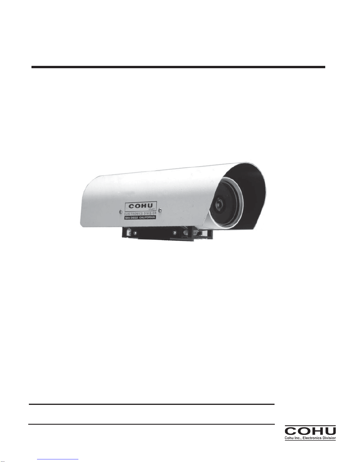
This introduction briefly describes overall
characteristics of the Model 2740 monochrome
Camera (figure 1) related to its installation and
operation.
1.1 Electrical Characteristics
The 2740 camera provides a highly sensitive
interline transfer CCD Camera in a pressurized
environmental housing. All electrical connections
are via a single 39 pin rear panel connector. Table
1 lists electrical, mechanical, and environmental
specifications for the 2740 Camera.
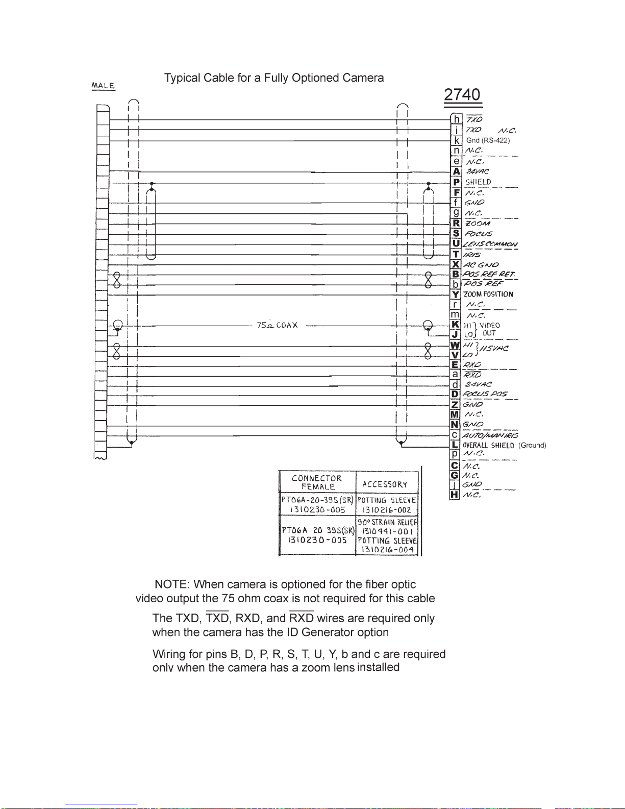
Video output may be provided by an optional
fiber optic connector added on the rear panel.
When this option is selected, the 75 ohm output
on the 39 pin connector should not be terminated.
Any temporary connections to this 75 ohm output
for maintenance purposes should be done with a
short 75 ohm coax cable to avoid any “stub” effect
that may cause ghosting in the video.
The Camera operates with either NTSC or
PAL format, depending on the model. Both of
these formats are available in a high-sensitivity
version.
This Camera operates at an internal clock rate
of 28.6363 MHz (NTSC) or 28.375 MHz (PAL).
If the phase adjust line lock option is installed,
the vertical interval of the camera is referenced to
the 60 Hz power input for NTSC (or the 50 Hz
power input for PAL). A six position switch on
the rear panel then makes it possible to shift
this reference in 60 degree increments so that
the camera can be phased with other cam-
eras in the system that may not have the
same power line phase reference. This phase
difference can occur either because the other
cameras are on a different phase of the power
source or perhaps because they are con-
nected to a power source operating from a
different transformer.
The Camera is available with either 115 V
ac or 24 V ac input power — depending on the
model. An internal 20 watt heater cycles on an
off at low environmental temperatures to maintain
temperature inside the housing at operating
levels.
When an optional zoom lens is installed,
dedicated pins on the connector provide for
control of zoom, focus, and iris. Pins are also
assigned for location of the lens zoom position.
When an optional ID generator is mounted
inside the camera housing, it can be programmed
to provide messages in the video. It also provides
barrel pressure and temperature when these
displays are turned on.
Programming and control of the ID generator
is via RS-422 on the rear panel multipin connec-
tor. Cohu’s Win MPC graphical user interface
(GUI) software can be used to program these
messages. (WinMPC is available at no cost from
the cohu-cameras web site or by mail on CD.) —
or the system control software can be used if it
has been implemented with the proper protocol
messages.
If either shuttering or a manual gain setting is
desired, these setting must be performed before
the camera housing is sealed and pressurized.
Changing either of these optional settings requires
complete disassembly of the camera housing. It
must then be re-sealed, purged with dry nitrogen,
and pressurized with the dry nitrogen before
returning to service. For more information about
the internal camera module refer to Cohu Techni-
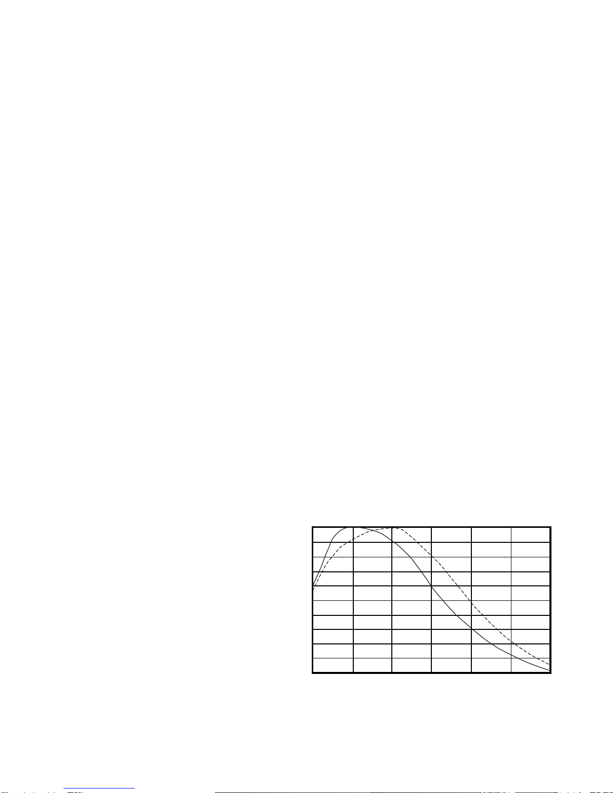
Figure 2. Sensor Wavelength
Response Characteristics
500
400 600 700 1000
900
800
0
0.1
0.2
0.3
0.4
0.5
0.6
0.7
0.8
0.9
1.0
Wavelength (nm)
Relative Response
Standard Sensitivity
Enhanced Near IR
Sensitivity
Note: Both curves are normalized to 1.0 and thus the graph does not show comparative output levels