COHU iDOME 3920 Series User manual

6X-1026 1
INSTALLATION AND OPERATION
3920iDOME
Cohu Electronics 3912 Calle Fortunada San Diego, CA 92123-1827
Phone: 858-277-6700
FAX:
Email: [email protected]
WEB: www.cohu-cameras.com
858-277-0221
Sept 27, 2002
Rev 1. 11-20-02
.
3920 SERIES
iDOME CAMERA/POSITIONER SYSTEM
Installation and Operation Manual
COHU, INC. ELECTRONICS DIVISION
Figure 1. iDome
1
1
2
NPT
8.340 10.419
O11.054
Unless otherwise noted, all dimensions in inches
NPT is National Pipe Thread
O6.990
O3.000
3.319
COHU
Cohu Inc., Electronics Division

6X-1026
2
INSTALLATION AND OPERATION 3920iDOME
TABLE
OF CONTENTS
LIST OF
TABLES
LIST OF
FIGURES
FIGURE TITLE PAGE
1 iDome 1
2 Model Number Interpretation Diagram 4
3 Basic Model Configurations 6
4 Model 8540B Test Stand 7
5 Type CTC-29 Cable, Test/ Setup Wiring Diagram 8
6 Typical RS-232 to RS-422 Converter 8
7 Quick Disconnect Assemby 9
8 Wall Mount Arm 9
9 Arm Dimensions 10
10 Typical Pole Mount 11
11 iDome Quick Disconnect Mounting 12
12 Strap Wrench 12
13 Pole Mount Dimensions 13
14 Mast Arm Mount 13
15 Intreconnection Diagram, iDome to Local Control Panel 14
16 Interconnection Diagram, iDome to Equipment Cabinet 15
17 Cable CA-295A (RS-422 ) Wiring Diagram 16
18 Cable CA-295B (RS-422) Wiring Diagram 16
19 Cable CA-295C (RS-422) Wiring Diagram 17
20 Cable CA-296A (RS-232) Wiring Diagram 17
21 Cable CA-296B (RS-232) Wiring Diagram 18
22 Cable CA-296C (RS-232) Wiring Diagram 19
23 iDome Pin Layout and Functions 19
24 Typical WinMPC Screen and Laptop 20
25 Typical WinMPC Main Screen 20
26 Typical WinMPC Communications Setup Screen 21
27 iDome Maintenance Features 24
TABLE TITLE PAGE
1 Specifications 3
2 Equipment vs. Model Number 5
3 Required Cable Characteristics 13
4 iDome Connector Functions 19
5 Communications Settings 19
SECTION TITLE PAGE
1.0 GENERAL DESCRIPTION 4
1.1 Electrical Characteristics 4
1.2 Mechanical Characteristics 5
2.0 INSTALLATION 5
2.1 Unpackin
g
and Receivin
g
Inspection 6
2.2 Static Dischar
g
e Protection 6
2.3 Installation Fundamentals 7
2.4 Equipment Supplied 11
2.5 Equipment Required But Not Supplied 12
2.6 Power Requirements 12
2.7 Pendant Mount Installation 13
2.8 Wall Mount Installation 13
2.9 Pole Mount Installation 15
2.10 Alternate Mountin
g
Methods 21
2.11 Cablin
g
Requirements 22
2.12 GUI Interface 22
2.13 Preparation for Shipment and Stora
g
e24
3.0 OPERATION 24
3.1 Local Panel Control 24
3.2 Local Laptop PC Control 25
4.0 MAINTENANCE 25
4.1 Troubleshootin
g
25
4.2 Preventive Maintenance 26

6X-1026 3
INSTALLATION AND OPERATION
3920iDOME
This equipment has been
tested and found to comply
with limits for class A digital
devices, pursuant to part 15 of
the FCC rules.
SPECIFICATION CHARACTERISTIC
Imager 1/4 inch color interline transfer CCD, progressive scan
Resolotion 470 horizontal tv lines
Lens Integral 23X optical, 3.6 to 82.8 mm with 10X digital, auto/manual focus
Sync Phase adjust line lock
Day/Night Switchover Day (color) / night (mono), manual or auto
Sensitivity
3 lux at 1/60 s (color day)
0.2 lux at 1/4 s (color day)
0.3 lux at 1/60 s (mono night)
0.02 lux1/4 s (mono night)
Power Input
120 V ac nominal: 89 - 135 V ac, 60 Hz per NEMA 2.1.2 standard TS2 for traffic
control systems
230 V ac nominal (207 - 253), 50 Hz
24 V ac nominal (21.6 - 26.4), 60 Hz
Power Interruption Confirms to NEMA 2.1.6 standard TS2
Power Transients/Interruptions Confirms to NEMA 2.1.4 TS2
Communications Opto-isolated serial port RS-232 and RS-422 with digital position feedback;
RS-485 available
Protocol Non-propritary Cohu standard, others optional (see figure 2, protocols)
Firmware Stored in flash memory; upgrade via serial port
Pan/Tilt 360° continuous pan, 0-90° down. Auto flip at 90°
Preset Speed >250°/second preset, at 0.1° accuracy
Presets 64
Title Generation 8 lines
Tours 8, each of 32 presets with dwell timer per preset per tour
Sectors 16 in the horizontal plane
Privacy Zones 8 programmable zones can be set for video blanking
Alarm Inputs 2 available
Environmental -34 to 74 °C Conforms to NEMA 2.1.5.1 standard TS2 for traffic control systems
Humidity 100 percent, relative
Pressurization Pressurized with dry nitrogen; IP Rating IP67, NEMA 4X
Weight 12 lb (5.5 kg) approximate
Table 1. Specifications

6X-1026
4
INSTALLATION AND OPERATION 3920iDOME
1.0GENERAL DESCRIPTION
The iDome series is an integrated camera/positioner
unit that integrates a high performance digital signal
processing camera, pan-and-tilt, and control re-
ceiver into one integrated package (figure 1).
Throughout this manual the entire assembly will
typically be referred to as the “iDome.”
Specifications are contained in table 1 and a model
number interpretation diagram is provided in figure 2.
This diagram can be used to interpret an existing
model number. An iDome can be operated via either
RS-232 or RS-422 communications depending on
which pins of the connector are used. Thus there is
no model number designation to reflect a choice for
the communications mode.
WARNING
Two versions of the iDome operate from voltages
that can be dangerous: model 3925 (115 V ac)
and model 3923 (230 V ac). Use all appropriate
care when installing and maintaining either of
these versions of the iDome.
1.1ELECTRICAL CHARACTERISTICS
The camera uses digital signal processing. It has an
internal source ID generator. Integration control plus
a built-in video storage card provides full color
continuous video even at very low light levels.
The iDome speeds are variable with maximums of
250° per second for pan and tilt. Pan range is a
continuous 360 degrees while the tilt range is 0 to
90 degrees from the horizontal with auto-flip at the
90° point. There are 64 preset positions with a
preset accuracy of 0.1 degree. When responding to
standard pan-preset or manual control, the iDome
can move with a pan speed of 250° per second.
This iDome will operate in temperature ranges from
-34° to +74° C and with winds of up to 90 mph. The
enclosure protects against salt, grime, dirt, and
moisture.
The integrated receiver/driver, contained within the
IDome, communicates using Cohu protocol mes-
sages and will also control the digital DSP camera
functions. All iDome functions are operable via either
Figure 2.Model Number Interpretation Diagram
392× — × × 0 × — ××××
POWER
SERIES
VIDEO
PROTOCOL FUTURE
USE
DOME MOUNT
3 230 Vac
4 24 Vac
5 115 Vac
3 NTSC Phase Adjust Line Lock
7 PAL Phase Adjust Line Lock
1 Cohu
2 American Dynamics
3 Pelco D
4 Ultrak
5 Vicon
6 Javelin
7 Kalatel
8 Philips
9 NTCIP (not currently available)
1 Clear
2 Smoked PEND
POLE
WALL
DSP color/mono 1/4 inch
progressive scan dome
camera, 3.6 to 82.8 mm
zoom lens
MODEL NUMBER INTERPRETATION DIAGRAM

6X-1026 5
INSTALLATION AND OPERATION
3920iDOME
RS-232 or RS-422 serial communications.
The iDome is fully compatible with existing Cohu
controllers. In case of power failure, all 64 preset
positions are stored in nonvolatile memory.
Each iDome “address” within a surveillance
system can be selected electronically from the
Monitoring Center. There are no mechanical dip
switches to set at the camera, and each unit
responds to the central command only if ad-
dressed. This provides greater integration flexibility
for the designer and more dynamic camera
control for the operator
1.1.1Control Software
WinMPC
WinMPC Graphical User Interface (GUI) software
is available for setting the address and performing
field tests when connected to a single camera. (It
cannot be used to control more than one camera
at a time.) The WinMPC software can be obtained
at no cost from either the Cohu-Cameras.com
web site or by mail on floppy disk
CAMS
The CAMS software is intended for controlling
multi-iDome systems when the Cohu MPC Master
Control Panel is the central control “intelligence”
for the system. All control and response com-
mands among the various equipment in the
system pass through the Master Control Panel.
NetCAMS
The NetCAMS software is intended for controlling
multi-iDome systems when a Windows based PC
is the central control “intelligence” for the system.
All control and response commands among the
various equipment in the system pass through the
Net Cams Server.
1.2MECHANICAL CHARACTERISTICS
Although the iDome is a single mechanical assem-
bly for installation purposes, it actually consists of
two primary subassemblies inside the dome: (1) the
camera and (2) the positioner.
All camera circuits are contained within a sealed and
pressurized environmental dome housing having
either a clear or smoked window for viewing through
by the camera lens. This dome is fully covered by a
sun shield spaced slightly away from the housing
itself. This minimizes heat buildup due to sunlight.
Vent holes at the top of the dome must be kept clear
to maintain air flow.
The iDome is a sealed and pressurized (dry nitro-
gen) unit intended for indoor or outdoor use under
rain, snow, and other typical harsh weather condi-
tions.
Communications circuits contained within the
iDome are also protected from outdoor weather
conditions. A single multiconductor cable passes
through the mounting pendant to provide for all
signal and operating power connections. Pin func-
tions and layout are shown in figure 23.
2.0INSTALLATION
Always preplan the installation to be sure that all
required cabling and address assignments are
completed. It may also be important to know the
orientation of the iDome when it is mounted at its
location. The Schrader valve should be accessible
for for adding dry nitrogen if necessary.
The model number label indicated a me-
chanical home reference for all iDomes.
Electrical home for panning is 90° clock-
wise from this position as viewed from
above.
Table 2 lists the three basic mounting
arrangements.
MOUNT
CONFIG. iDOME ARM POLE
BRACKET
Pendant •
Wall ••
Pole •••
NOTE: Dot
( • )
designates items supplied for each mounting
configuration.
Table 2. Equipment vs. Model Number

6X-1026
6
INSTALLATION AND OPERATION 3920iDOME
2.1UNPACKING AND RECEIVING INSPECTION
This iDome was thoroughly tested and carefully
packed in the factory. Upon acceptance by the
carrier, they assume responsibility for its safe arrival.
Should you receive this item in a damaged condition,
apparent or concealed, a claim for damage must be
made to the carrier. To return an iDome or related
product to the factory for service, please contact the
Customer Service Department for a Return Authori-
zation Number.“ If a visual inspection shows dam-
age upon receipt of this shipment, it must be noted
on the freight bill or express receipt and the notation
signed by the carrier's agent. Failure to do this can
result in the carrier refusing to honor the claim.“
When the damage is not apparent until the unit is
unpacked, a claim for concealed damage must be
made. Make a mail or phone request to the carrier
for inspection immediately upon discovery of the
concealed damage. Keep all cartons and packing
materials. Since shipping damage is the carrier's
responsibility, the carrier will furnish you with an
inspection report and the necessary forms for filing
the concealed-damage claim
2.2STATIC DISCHARGE PROTECTION
Procedures in this manual do not require entry into
the housing of the iDome. However in the event that
an open unit were available, the following precau-
tions should be followed:
CAUTION
This iDome contains sensitive devices that can
be damaged by static discharge. Use appropri-
ate static control methods when working inside
the iDome.
Components used in modern electronic equipment,
especially solid state devices, are susceptible to
damage from static discharge. The relative suscep-
tibility to damage for semiconductors varies from
low with TTL to high with CMOS. Most other semi-
conductors fall between TTL and CMOS in suscepti-
bility to static discharge. As a minimum, therefore,
observe the following practices when working inside
this or any other electronic equipment:
1. Use conductive sheet stock on the work bench sur-
face.
2. Connect the sheet stock to ground through an 1
megohm or greater value resistor.
3. Use a wrist strap connected to ground through an 1
megohm or greater value resistor when working at
the bench.
4. Maintain relative humidity of the room above 30 per-
cent. This may require a room humidifier. Working
on circuits with relative humidity below 30 percent
requires extraordinary procedures not listed here.
5. Use antistatic bags to store and transport an ex-
poses chassis, circuit boards, and components.
Usenewantistatic bags.Old,used bagsloosetheir
static protection properties.
This list serves as a reminder of the minimum
acceptable practices. Be sure that all static dis-
charge devices at the work bench are properly
installed and maintained.“ Standard grounding mats
and wrist straps purchased for use at work benches
are supplied with leads having current limiting
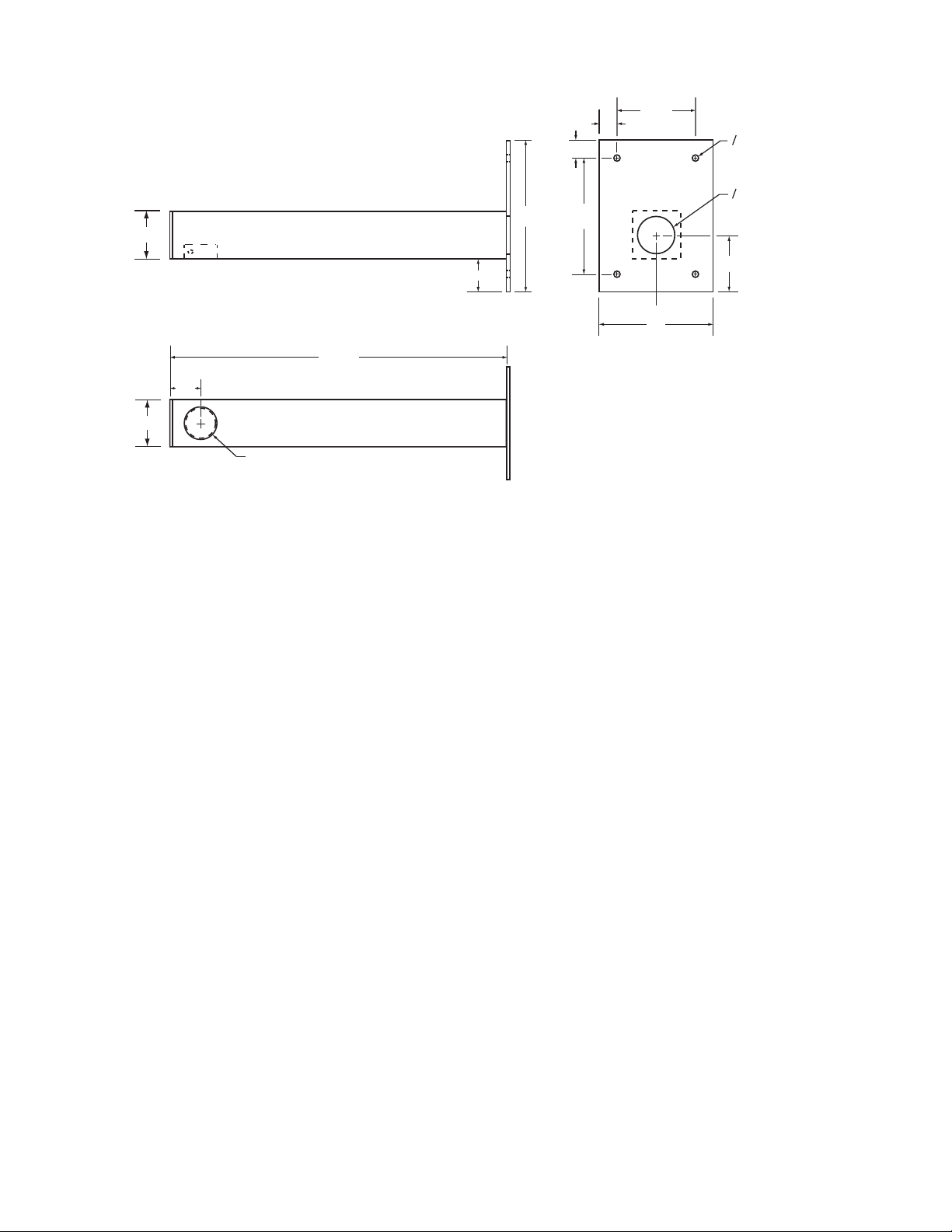
PENDANT MOUNT
WALL MOUNT
POLE MOUNT
Figure 3. Basic Mounting
Configurations

6X-1026 7
INSTALLATION AND OPERATION
3920iDOME
resistors for safety. Never substitute with a ground-
ing lead not having the resistor.
2.3 INSTALLATION FUNDAMENTALS
2.3.1 Basic Mounting Configurations
An iDome can typically be mounted in any one of
three mechanical configurations (figure 3):
1.Pendant Mount
The basic configuration. The iDome hangs directly
from a supplied 1.5-inch female NPT (national pipe
thread) support. This support must provide for the
connector of a multiconductor cable to pass down
through the 1.5-inch pipe nipple for mating with the
iDome.
2.Wall Mount
This mounting arrangement requires an arm that
bolts to the wall. The iDome hangs from the end of
this arm.
3.Pole Mount
This mounting arrangement is similar to the Wall
Mount -- except that the mounting arm attaches to a
bracket fastened to a pole instead of directly bolting
to a wall.
Table 2 summarizes the major items supplied for
each of these three installation methods. Each of
these installations will be expanded upon in a later
sections.
2.3.2 Installation Checklist
Before starting the installation of an iDome the
following check lists should be read for an overview
of the process.
2.3.2.1 Test Bench Checkout - To check out an
iDome and set its address at a test bench before
taking it into the field for installation, use the following
as a guideline:
1. Mount the iDome to a test stand (figure 4). This
Figure 4. Model 8540B Test Stand (23-inch height).
( Model 8540A -not shown- provides 38-inch height)

6X-1026
8
INSTALLATION AND OPERATION 3920iDOME
Figure 5. Type CTC-29 Cable , Test/Setup, Wiring Diagram
232
D9
FEMALE
B & B
Model 422PP9TB
B&B Electronics
707 Dayton Road
PO Box 1040
Ottawa IL 61350
www.bb-elec.com
+12V
GND
RD(B)
RD(A)
TD(A)
TD(B)
422
CONVERTER
(Also Available from Cohu as P/N 3010100-001)
Rx-
Rx+
Tx+
Tx-
TO iDome
MAY BE REQUIRED
SEE TEXT
Figure 6. Typical RS-232 to RS-422 Converter
This converter changes the RS-232 output of a PC to RS-422 for
communications with an iDome during field setup and testing.
A local PC with Win MPC software typically is used in this appli-
cation.
If this converer is plugged into the RS-232 output from an F/0
converter, 12 V dc operating power will likely have to be applied
to the 12 V dc terminal lugs. These F/O to RS-232 converters
typically do not have sufficient current on the handshake lines to
power the 232/422 converter. This application of the 232/422
converter would typically occur as part of a fixed installation in-
side an equipment cabinet located near an iDome. The 232/422
converter would be part of a type CA-295C cable.

6X-1026 9
INSTALLATION AND OPERATION
3920iDOME
stand is also available with another set of three legs
that increases it from a 20-inch height to 38 inches.
2. Connect the test cable (figure 5) to the
connector at the top of the dome
3. Connect the other end of the cable to
the laptop. (Either a test cable with
integral RS-232 to RS-422 converter or
separate converter must be used. See
figures 5 and 6.)
CAUTION
Step 4 assumes that the iDome operates
from 115 V ac power. If a 230 V ac iDome
is to be operated from this cable, a 115/
230 adapter will have to be used. This
cable cannot be used with an iDome op-
erating from 24 V ac. Different connec-
tor pins are used.
4. Connect the power plug of this cable to
115 V ac — or for a 230 V ac iDome, use an
adapter on this plug to connect to 230 V ac.
(This cable cannot be used with 24 V ac
iDomes.)
5. Connect a tv monitor to the cable. This
monitor must be terminated with 75 ohms.
Monitors typically have a rear panel switch
to select either 75 ohms or no termination
(Only the end of the coax cable can be
terminated with 75 ohms. Any other equip-
ment connected on the cable in a loop-
through arrangement must present a high
impedance to the line.)
1.5-inch NPT Nipple
Lock Bolt (1)
Dome
Safety Strap
Figure 7. Quick Disconnect Assembly
Figure 8. Wall Mount Arm
ARM
WALL
Route system
cable through
hole in wall
into Arm
Use weather-tight gasket
between Arm and wall
1.5 NPT
for dome
quick disconnect
adapter

6X-1026
10
INSTALLATION AND OPERATION 3920iDOME
6. Install Win MPC software on the laptop. (See
section 2.12 for details about using Win MPC.)
7. Establish the required communications param-
eters
8. Set (or verify) the iDome address (When installed
in the system, each item of equipment must have a
unique address). Place this address on the iDome
with a removable piece of masking tape.
9. Verify proper operation of all the various functions
controllable through the Win MPC menus.
10. Release the iDome for field installation after it
has been determined all functions are working.
2.3.2.2. Field Installation Procedure - Use
the following outline to become familiar with the
steps requried to install an iDome at its field location:
1. Route the cable to the mounting location of the
iDome.
2. Route the cable through any mounting arms or
brackets.
3. Remove the safety strap from the iDome quick
disconnect fastener
4. Thread the nipple portion of the quick disconnect
into the mounting bracket or arm.
5. Route the cable down through this nipple and
attach it to the iDome connector
6. Attach the dome half of the quick disconnect to
the half mounted to the arm or other bracket. (If a
particular orientation is required be sure to mount it
correctly positioned.)
7. Attach the safety strap back to the other half of the
quick disconnect.
8. Connect the laptop to the iDome at the junction
box or equipment cabinet.
9. Verity (or set) the address and check all opera-
tions.
10. Release the iDome for service.
O2.0
O0.375
(TYP 4 PLACES)
4.50
0.75
0.75
6.50
8.0
1.75
6.0
1.5 NPT
1.75
2.0
17.75
3.0
UNLESS OTHERWISE NOTED ALL DIMENSIONS IN INCHES
2.0
Figure 9. Arm Dimensions

6X-1026 11
INSTALLATION AND OPERATION
3920iDOME
2.4EQUIPMENT SUPPLIED
Depending on the mounting configuration, several
variations of equipment can be supplied. See table 2
for a list of the basic differences between models.
PEDD (Pendant Mount). See figure 7.
Pendant mounting is the most basic of the three
mounting arrangements. The top half of a quick-
disconnect assembly is threaded into a site supplied
1.5-inch NPT mount.
WALL (Wall Mount). See figure 8.
With a wall mount the iDome hangs from the end of
an arm which is attached to a wall. Figure 9 gives
dimensions of the arm and adapter plate. This wall
must not only have four mounting bolts but also a
hole centered between these bolts through which
the cable must pass. A weather-tight gasket should
be used between the arm and wall.
POLE (Pole Mount). See figure 10.
Mounting to a pole is similar to mounting to a wall.
For mounting to a pole, the four mounting bolts are
provided by a bracket. This bracket is attached to
the pole by stainless steel straps. This strapping
requires a special tensioning tool.
Cable routing when using a pole mount depends
ARM
DOME
POLE MOUNT
Figure 10. Typical Pole Mount

6X-1026
12
INSTALLATION AND OPERATION 3920iDOME
upon the situation encoun-
tered. It can either be directed
down behind the pole bracket
or, if arrangements have
been made for this, into the
pole. Junction boxes, drip
loops, and weather proof
integrity of the connectors
must be considered before
starting the installation.
2.5EQUIPMENT
REQUIRED BUT NOT
SUPPLIED
5/16 stainless steel mounting
hardware
Cable, multiconductor or
individualcables
Male BNC cable connector
Win MPC test and setup GUI
Data control such as CAMS
orNetCAMS GUI
2.6POWER
REQUIREMENTS
There are three versions of the
iDome related to power:
115 Vac (Model 3925-xxxx-x)
230Vac (Model3923-xxxx-x)
24Vac (Model3924-xxxx-x)
The model number lable is attached to the bottom of
an iDome. (Electrical home for camera pan is 90°
clockwise from this lable viewed from above.)
At 120 V ac 60 Hz the iDome heaters draw 72 watts
during cold weather when the thermostat has them
turned on. Otherwise power consumption is 27
watts with the stepper motors idle or 50 watts when
they are active. Thus the maximum power draw at
any one time is 122 watts at 120 V ac.
All electrical connections to and from the iDome are
made through a single cable entering at the top.
Power for 115 and 230 V ac versions of the iDome
use the same connector pins (“U” hot/high and “T”
Safety Strap
Mounting Lug Slot
(4)
Lock Bold Detent (4)
(1 used)
Lock Bolt Threaded Hole (2)
(1 Used)
Mounting Lug (4)
Dome can be mounted to fixed collar at any of
four positions - in 90° increments
Dome
Dome
Collar
Fixed
Collar
Position the Dome between 90° increments by
rotating the Fixed Collar ±45° with a strap wrench
NOTE:
Figure 11. iDome Quick Disconnect Mounting
Figure 12. Strap Wrench

6X-1026 13
INSTALLATION AND OPERATION
3920iDOME
CONDUCTOR
FUNCTION CHARACTERISTICS
VIDEO
RG-59/U (75 ohm), 100 % copper conductor,
95% minimum braided shield
DATA
2 pair, twisted with overall shield, 26 AWG
minimum (Belden 8723 or equivalent)
POWER
3-CONDUCTOR, 22 AWG (Belden 19401 or
equivalent)
NOTE: For distances exceeding 250 feet, please contact an
Application Engineer at Cohu Electronics
.
Table 3. Required Cable Characteristics
low/neutral).
But for 24 V ac versions of the iDome, pins “B”
(hot/high) and “T” (low) are used.
Ac ground in all cases is pin “G.”
2.7PENDENT MOUNT INSTALLATION
An iDome in the pendent configuration is its
most basic form. No mounting arms or adapt-
ers are provided. The 1.5 inch NPT pipe thread
on top the dome is attached to an appropriate
mount supplied by the installer. Provisions must
be made for the cable to pass through this
mount down through the quick disconnect
mount (figure 11) and onto the connector on top
the iDome.
2.8WALL MOUNT INSTALLATION
With a wall-mount installation, a support arm
bolts to a wall and the iDome then hangs from
the end of that arm.
1. Remove the safety strap from the top half of
the quick disconnect (the half with the threaded
nippleattached).
2. Thread the quick disconnect nipple into the
mounting arm and tighten with a strap wrench
(figure 12).
Figure 13. Pole Mount Dimensions
Figure 14. Mast Arm Mount

6X-1026
14
INSTALLATION AND OPERATION 3920iDOME
Figure 15. Interconnection Diagram, iDome to a Typical Local Control Panel
POWER
VIDEO
HOSTCAMERA
OUTRS422 IN +12 VDC
12 VDC
POWER
SUPPLY
DOME
115VAC
SOURCE
CABLE
ER8508A3
CENTRAL
CONTROL
STATION
NOTE:THE VIDEO LINE
MUST BE TERMINATED
WITH 75 OHMS FOR
PROPER OPERATION
NOTE: This panel is optional. It is used only
when on-site control of an iDome is desired
for setup and maintenance operations
(FRONT OF TYPICAL LOCAL CONTROL PANEL)
Change 1

6X-1026 15
INSTALLATION AND OPERATION
3920iDOME
Figure 16. Interconnection Diagram, iDome to Equipment Cabinet
3. Verify that the system cable is accessible for
connection to the iDome connector at the end of the
arm. This cable typically must pass through the wall
and into the arm.
4. Route the system cable out of the wall and into
the back of the wall mount arm. Continue the cable
through the arm and out the hole at the iDome
mounting location.
5. Install a weather tight gasket between the arm
and the surface of the wall.
6. Bolt the Arm to the wall.
7. Attach the cable plug to the iDome connector.
9. Orient the iDome properly and attach it to the
other half of the quick disconnect mounted to the
arm.
10. Reattach the safety strap.
11. Proceed to section 2.12.4, the checkout proce-
dure.
2.9POLE MOUNT INSTALLATION
A pole mount installation is similar to the wall mount
installation except that the arm fastens to a bracket
(figure 13) attached to the pole instead of directly to
a wall. Attaching the pole mount to a pole requires
the use of a tensioning tool to properly tighten and
secure the stainless steel straps.
TYPICAL INSTALLATION
FO CABLE
POWER
CORD
75 OHM
TWISTED PAIR
SERIAL DATA
WIRES
NOTE:THE VIDEO LINE
MUST BE TERMINATED
WITH 75 OHMS FOR
PROPER OPERATION
COAX
115
VAC
CABLE
CA295B
(LUGS ADDED)
FO
115 VAC
RS422
iDome
CONDUIT
CONDUIT
75 OHM
VIDEO IN
RS422
DATA
TERMINAL
STRIP
FIBER OPTIC
TRANSCEIVER
EQUIPMENT CABINET

6X-1026
16
INSTALLATION AND OPERATION 3920iDOME
Figure 17. Cable CA295A (RS-422) Wiring Diagram
Figure 18. Cable CA295B (RS-422) Wiring Diagram

6X-1026 17
INSTALLATION AND OPERATION
3920iDOME
Figure 19. Cable CA295C (RS-422) Wiring Diagram
Figure 20. Cable CA296A (RS-232) Wiring Diagram

6X-1026
18
INSTALLATION AND OPERATION 3920iDOME
Figure 22. Cable CA296C (RS-232) Wiring Diagram
Fitgure 21. Cable CA296B (RS-232) Wiring Diagram

6X-1026 19
INSTALLATION AND OPERATION
3920iDOME
PIN FUNCTION
A Video Shield (75 ohm )
B 24 V ac high
Cnotused
D RS-232 Response Out (Tx)
E RS-232 Command In (Rx)
F RS-232 RTS
G 24 or 115 or 230 V ac Ground
H RS-232 CTS
Jnotused
Knotused
L Video Out (75 ohm)
M RS-422 Command In + (Rx+)
N RS-422 Command In - (Rx-)
P RS-422 Ground
R RS-422 Response Out - (Tx-)
S RS-422 Response Out + (Tx+)
T 24 or 115 or 230 V ac neutral (low)
U 115 or 230 V ac line (hot/high)
An iDome is wired for either 24, 115, or 230 V ac.
The model number designates which power
configuration is present.
Mating view of connector
on the dome housing. Pin
layout same as wiring view
of mating cable connector.
A
NB
M
KL
JTUP
C
D
R
S
H
GFE
Figure 23. iDome Pin Layout Functions
COMMUNICATIONS
FUNCTION SETTING
Port COM 1 (Typical. Verify)
Baud Rate 9600
Pan/Tilt
Var Speed P/T
Max Pan Speed = 15
Max Tilt Speed = 15
Comm Mode PC to MPC Receiver
Camera Day/Night
Receiver iDome/iView
Table 5. Communications SettingsTable 4. iDome Connector Functions
S
R
B
C
D
M
N
K
E
F
H
G
U
L
A
T
J
Spare
Spare
Response Out + (Tx+)
Response Out - (Tx-)
Command In - (Rx-)
Command In (Rx)
Command In + (Rx+)
Spare
232
RTS
CTS
115 or 230 V ac Ground
hot/line
neutral
Spare
Video out
Video Shield
115 or 230 V ac
422
422
75 ohm
coax
Response Out (Tx)
P
422 Ground
115/230 VAC VERSION
232
S
R
B
C
D
M
N
K
E
F
H
G
U
L
A
T
J
Spare
Spare
Response Out + (Tx+)
Response Out - (Tx-)
Command In - (Rx-)
Command In (Rx)
Command In + (Rx+)
Spare
232
RTS
CTS
115 or 230 V ac Ground
Spare
Video out
Video Shield
24 V ac low
422
422
75 ohm
coax
Response Out (Tx)
P
422 Ground
24 V ac low
232
24 VAC VERSION

6X-1026
20
INSTALLATION AND OPERATION 3920iDOME
WIN
MPC
Figure 24. Typical Win MPC Screen and laptop
Figure 25. Typical Win MPC Main Screen
This manual suits for next models
2
Table of contents
Other COHU Security Camera manuals

COHU
COHU 3940 Analog iDome User manual

COHU
COHU Series 7520HD User manual

COHU
COHU 7100 SERIES User manual

COHU
COHU 3950 SERIES iVIEW User manual

COHU
COHU 3220 Series User manual

COHU
COHU 7420HD series User manual

COHU
COHU 7510HD SERIES User manual

COHU
COHU 2900 Series User manual

COHU
COHU 3920HD series User manual

COHU
COHU 3610 Series Product manual
Popular Security Camera manuals by other brands

ARTRAY
ARTRAY ARTCAM-445KY2 Series Instruction booklet

nest
nest NEST CAM OUTDOOR installation guide

Speco
Speco Intensifier O2iBD3 Quick installation guide

Marshall Electronics
Marshall Electronics CV620-WH installation guide

Vitek
Vitek Transcendent 4 Series quick start guide

Genie
Genie GB83TSPXIR Instruction guide