If your Statim unit has been idle for a prolonged period of
inactivity, (e.g. for > 2 weeks) Scican recommend that a series
of checks and set-up procedures are undertaken before the
unit is returned to clinical use so that its operation will not
compromise the ecacy of your instruments when rst used.
The following procedure is based on the assumption that
during the period of inactivity, the unit and its accessories
have been dismantled and stored away from the clinical area.
If that is not the case, then certain parts of this procedure
may be ignored.
STATIM®G4 Cassette Autoclaves | Product Advice Sheet
1. MAIN UNIT
1.1. Check that all the following component parts of
the system are readily available.
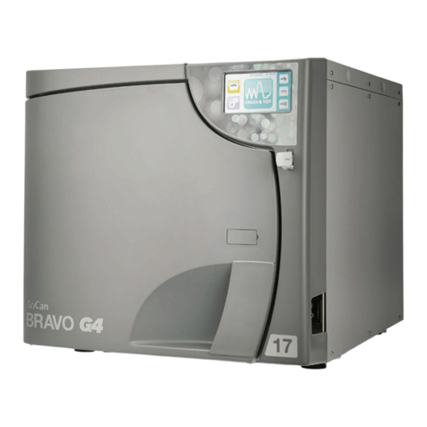
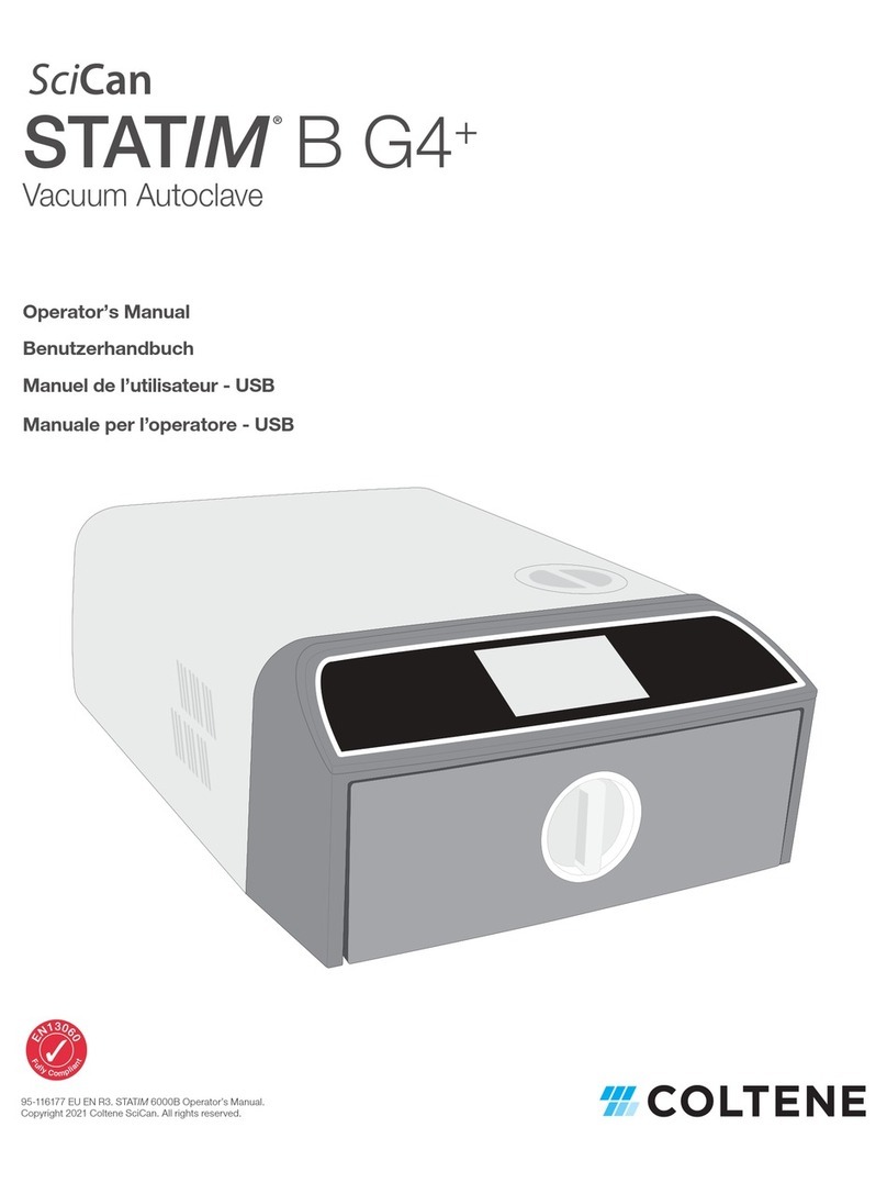
Statim main unit
Cassette(s)
Instrument rack for cassette
Drying plates for cassette (5000 only)
Power cord
Waste bottle complete with lid, connector
tting and condenser
Exhaust tube
1.2. If appropriate, relocate the main unit in the clinical
area where it will be used.
1.3. Check the level of the unit and adjust if necessary.
The level bubble on Statim
Classic unit is visible on the
front, right hand side of the
fascia.
NOTE: that the correct level
is with the bubble in the ‘4
O-clock’ position, NOT in the
centre.
The level bubble on Statim
G4 unit is an electronic level
that is displayed on the touch
screen when the correct menu
selection is made. The menu
order is:
NOTE
That the correct level is with the bubble in the ‘4 O-clock’
position, NOT in the centre. It will be GREEN when in the correct
position and RED when out of position.
1.4. Before returning the unit to service, Scican
recommend cleaning the external surfaces of the
unit with OPTIM™Cleaning and Disinfection wipes.
These have been tested on the external surfaces of
Statim units and are compatible with the materials
used.
NOTE
We do not recommend the use of any other type of chemical on
the unit as they have not been tested. In the absence of OPTIM™
use a soft, lint free cloth moistened with soap and water to wipe
down the surfaces. Dry the surfaces thoroughly after cleaning.
1.5. If appropriate, reassemble the system components
as follows;
I. Insert the exhaust tube 2into the tting on the
back of the unit 3(ensure it is FULLY inserted) and
pull gently to conrm a tight t.
II. Insert the other end of the exhaust tube into the
waste bottle tting. Tighten the tting 4to ensure
the exhaust tube is sealed in the tting. Tip – at
this stage it may be appropriate to check that all
the parts of the tting are tightened to ensure the
condensing coil is not loose and a good seal is
made with the lid.
III. Fill the waste bottle 1to the minimum level
shown on the side of the bottle with water. (A
low-level disinfectant, prepared according to the
manufacturer’s instructions, may be added to the
waste bottle to prevent bacterial growth in the
wastewater.)
IV. Attach (screw) the waste bottle 1and lid assembly
5together and locate the waste bottle assembly
close to the unit but BELOW the unit.
Check that the exhaust tube is not bent or
kinked as this will restrict the ow of steam and
condensate out of the unit.


