INSTALLATION GUIDE FOR RA-8000
RA-8000 QI Copyright - refer to title page Page 4
ENU Status : 1-0-0
0.3 INDEX TO FIGURES AND TABLES
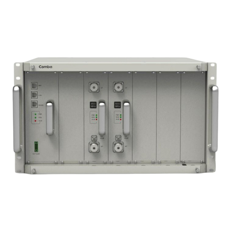
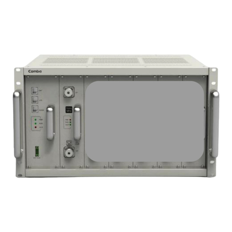
Figure 1: View of MOU Fully Equipped Shelf .......................................................................................10
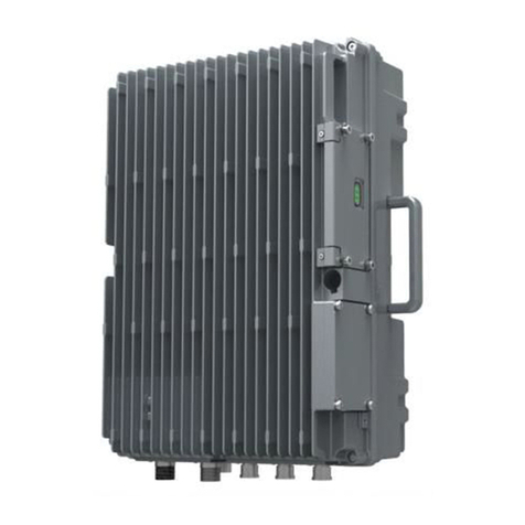
Figure 2: Front, Side and Bottom Views of RRU Enclosure.................................................................10
Figure 3: MOU System Diagram...........................................................................................................11
Figure 4: RRU System Diagram ...........................................................................................................11
Figure 5: Application of one MOU with one RRU through Single Channel FOU with Internal WDM...12
Figure 6: Application of one MOU with two RRUs through Dual Channel FOU with Internal WDM ....12
Figure 7: Fully Equipped Front View of MOU .......................................................................................13
Figure 8: RRU Equipment Layout.........................................................................................................14
Figure 9: Rack Mounting of 19” Shelf ...................................................................................................21
Figure 10: RRU Mounting Rack Dimension..........................................................................................22
Figure 11: RRU Enclosure Lifting Lug Attachment Details...................................................................23
Figure 12: RRU Mounting Rack Wall Mounting....................................................................................23
Figure 13: Pole Mounting of RRU Mounting Rack................................................................................24
Figure 14: Attaching the RRU onto the Mounting Rack........................................................................25
Figure 15: MOU Back Panel View ........................................................................................................30
Figure 16: RRU Connectors..................................................................................................................31
Figure 17: Pins Allocation for “EXT_ALM” Port ....................................................................................34
Figure 18: Pin Allocation for “BTS_ALM” Port......................................................................................35
Figure 19: RF Connection between RFU and Single Output in FOU1.................................................36
Figure 20: RF Connection between RFU and Two Outputs in FOU1 ..................................................36
Figure 21: RF Connection between RFU and Two Outputs in FOU1, One Output in FOU2...............37
Figure 22: RF Connection between RFU and Two Outputs in FOU1, Two Outputs in FOU2 .............37
Figure 23: Wireless Modem..................................................................................................................37
Figure 24: Diagram of wireline modem.................................................................................................38
Figure 25: Location of RRU LED Indicators..........................................................................................41
Figure 26: Connection Type..................................................................................................................42
Figure 27: Serial Port Configuration......................................................................................................42
Figure 28: Remote Connection.............................................................................................................42
Figure 29: OMT Main Window..............................................................................................................43
Figure 30: System Information..............................................................................................................43
Figure 31: RRU Switch .........................................................................................................................44
Figure 32: MOU ATT.............................................................................................................................44
Figure 33: MOU Alarm Threshold.........................................................................................................45
Figure 34: RRU Alarm Threshold..........................................................................................................45
Figure 35: MOU Master Alarm..............................................................................................................46
Figure 36: MOU Channel Alarm............................................................................................................46
Figure 37: RRU Master Alarm...............................................................................................................46
Figure 38: RRU External Alarm ............................................................................................................47
Figure 39: MOU Equipment ID..............................................................................................................48
Figure 40: ROU Equipment ID..............................................................................................................48
Figure 41: MOU Comm.Config .............................................................................................................49
Figure 42: “O” ring fitting details............................................................................................................52
Table 1: MOU Shelf Equipping Rule.....................................................................................................13
Table 2: RA-8000 Regular KOP............................................................................................................16
Table 3: MOU KOP...............................................................................................................................16
Table 4: RRU KOP................................................................................................................................16
Table 5: Repeater Installation Checklist...............................................................................................19
Table 6: PSU SIU Description...............................................................................................................27
Table 7: MCU SIU Description..............................................................................................................28
Table 8: Single Channel FOU SIU Description.....................................................................................29
Table 9: Dual Channel FOU SIU Description .......................................................................................29
Table 10: MOU Back Panel Connectors...............................................................................................30
Table 11: RRU connectors....................................................................................................................31
Table 12: Pin Definition of “EXT_ALM” Port .........................................................................................34
Table 13: Voltage Applied to EXT_ Alarm1~4......................................................................................34
Table 14: Pin definition of the BTS_ALM port.......................................................................................35
