Comelit KSW3208LU User manual

TECHNICAL
MANUAL
EN
SECUR HUB

2
Contents
Contents........................................................................................... 2
Control panel description ............................................................... 3
Installing the control panel............................................................. 3
Removing the backplate..........................................................................3
Installing the LAN module .......................................................................4
Installing the 2G/3G module....................................................................4
Replacing the backplates........................................................................4
Choosing the correct mounting position...............................................5
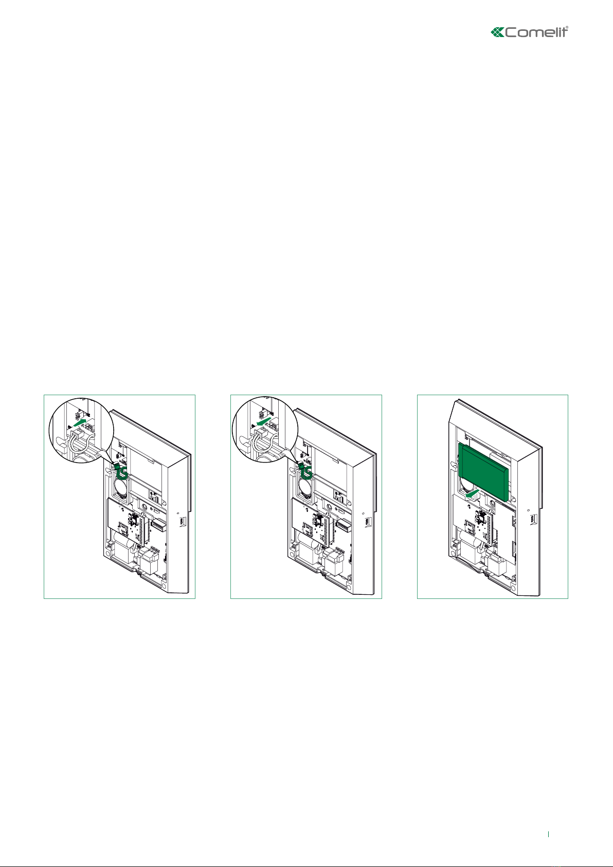
Connecting/replacing the battery...........................................................5
Installing the wall mounting backplates ................................................6
Installing the desk base...........................................................................6
The front panel................................................................................. 7
Switching on for the first time........................................................ 7
Accessing the technical menu ....................................................... 8
Installation Wizard........................................................................... 8
GSM/3G settings ......................................................................................8
Connect to Wi-Fi? ....................................................................................9
Connect to LAN? ....................................................................................10
Set date/time? ........................................................................................10
Entry/exit time? ......................................................................................11
Set zones? ..............................................................................................12
Set Sounders? ........................................................................................13
Set users? ...............................................................................................14
Set phonebook? .....................................................................................15
Connect App?.........................................................................................15
Extended menu.............................................................................. 16
Maintenance .................................................................................. 16
Time and date.........................................................................................16
Event log ................................................................................................16
Cloud syst. name....................................................................................16
Tamper mask ..........................................................................................18
Default management .............................................................................18
Assign codes ..........................................................................................18
Find RF device........................................................................................19
Forced settings.......................................................................................20
Language ................................................................................................20
Technical reset .......................................................................................20
FW Version..............................................................................................20
FW Update ..............................................................................................20
Manuf. code............................................................................................20
Disable installer?....................................................................................20
Format SD card ......................................................................................20
Timing menu .................................................................................. 21
Enter time................................................................................................21
Exit time ..................................................................................................21
Sounder time ..........................................................................................22
Alarm time...............................................................................................22
Sched. programming .............................................................................23
Profiles and codes......................................................................... 26
Access levels..........................................................................................26
Installer code..........................................................................................26
Devices........................................................................................... 27
Radio zones ............................................................................................27
Wired zones ............................................................................................33
Keypads ..................................................................................................33
Radio outputs .........................................................................................36
Wired outputs .........................................................................................38
Video devices .........................................................................................38
RF repeaters ...........................................................................................39
Remotes..................................................................................................39
Areas............................................................................................... 40
Number of areas.....................................................................................40
Areas description ...................................................................................40
Assign zones ..........................................................................................40
Areas logic ..............................................................................................40
Communicator ............................................................................... 41
Directory .................................................................................................41
Event send settings................................................................................42
Message recording ................................................................................43
Audio options .........................................................................................44
Send event opt. ......................................................................................45
Communic. channels .............................................................................47
System options .............................................................................. 48
Arming opt. .............................................................................................48
Arming programs ...................................................................................49
Monitoring time ......................................................................................50
Anti-jam...................................................................................................50
Green LED...............................................................................................50
Panic alarm .............................................................................................50
Robbery alarm ........................................................................................51
Technical reset .......................................................................................51
Macro ......................................................................................................51
Hardware sett. ........................................................................................52
False code...............................................................................................53
Alarm reset .............................................................................................53
Memory reset .........................................................................................53
Save log-in/out .......................................................................................53
Menu timeout..........................................................................................54
FW download..........................................................................................54
Walk Test opt. .........................................................................................55
Chime duration.......................................................................................55
Warning
• This Comelit product was designed for use in the creation of security systems in residential, commercial or industrial settings and in public buildings or buildings
used by the public.
• All activities connected to the installation of Comelit products must be carried out by qualified technical personnel, with careful observation of the indications
provided in the manuals / instruction sheets supplied with those products.
• Cut off the power supply before carrying out any maintenance procedures.
• Use wires with a cross-section suited to the distances involved, observing the instructions provided in the system manual.
• We advise against running the system wires through the same duct as the power cables (230V or higher).
• To ensure Comelit products are used safely: carefully observe the indications provided in the manuals / instruction sheets and make sure the system created
using Comelit products has not been tampered with / damaged.
• Comelit products do not require maintenance aside from routine cleaning, which should be carried out in accordance with the indications provided in the
manuals / instruction sheets. Any repair work must be carried out: for the products themselves, exclusively by Comelit Group S.p.A., for systems, by qualified
technical personnel.
• Comelit Group S.p.A. does not assume any responsibility for: any usage other than the intended use; non-observance of the indications and warnings contained
in this manual / instruction sheet. Comelit Group S.p.A. nonetheless reserves the right to change the information provided in this manual / instruction sheet at
any time and without prior notice.

3
Control panel description
Installing the control panel
Removing the backplate
21
2
3
14
5
8
7
6
10 11
9
1. LCD/CAP-SENSE front panel
2. Microphone
3. Micro USB connectors
4. Battery
5. Battery connector
6. Loudspeaker
7. 2G/3G module connector
8. Tamper switch
9. RJ45 Ethernet connector
10. Wired input / output terminal block
11. A/C supply terminal block

4
Installing the LAN module
Installing the 2G/3G module
21
21 3
21
Replacing the backplates

5
Choosing the correct mounting position
Connecting/replacing the battery
When choosing the correct mounting position for the control panel, take the following factors into account.
Functional factors:
• When the control panel is on and running, a wireless network is established: avoid fitting the control panel near sources of
RF noise, such as large electrical appliances or air conditioners.
• The control panel should be located in a central position in relation to your wireless peripherals.
• Avoid positioning the control panel near large metal objects or large surfaces.
• Radio frequency transmission is adversely aected by metal-based building materials; consider the option of minimising
this type of obstruction.
• Depending on the communication channels you intend to use, the control panel should be fitted so as to oer good GSM
or WiFi signal strength.
• You will need to consider the availability of electricity mains and Ethernet connections.
Safety factors:
• The control panel should be fitted so that access while it is armed activates at least one detection zone.
• Install the control panel in a place that cannot be seen from outside the monitored areas.
• Keep it out of reach of children, to avoid unforeseen and unintentional operation.
Usability factors
• The control panel should be mounted at a height between 1.2 m and 1.8 m.
• Avoid installing the control panel behind doors or other obstacles which could cause delays in working with it.
Once the battery has been replaced, the control panel should be reconnected to the backplate immediately so that it can start up
using the main power supply and not just the battery.
Observe local regulations for correct battery disposal.

6
Installing the wall mounting backplates
Installing the desk base
21 3
2A1A 3A
21 3
54 6

SYSTEM BOOTING
LANGUAGE ↓↑
ENGLISH
1
2
34
5 6 7
Launch Wizard?
No:x Ok:↵
7
The front panel
1. 16 x 2-character LCD.
2. LED indicators: green, orange, red.
3. Alphanumeric keypad.
4. Arming/disarming buttons.
5. Back/Cancel/Delete button.
6. Enter/Confirm button.
7. Navigation keypad / menu button.
• Green LED: indicates the system is armed (steady) or that it is not ready to arm (flashing).
• Orange LED: indicates a fault in the system (steady) or the presence of isolated / bypassed zones (flashing).
• Red LED: indicates an alarm / tampering in progress (steady) or an alarm in the system memory (flashing).
Switching on for the first time
The first time it is switched on, the control panel will ask you to select a language.
Use the Down/Up arrow on the navigation keypad to select the language you want and confirm by pressing Return.

16:25 15/11/2019
****.. Technical menu
Launch Wizard
2G/3G settings
< Ok:↵>
SIM Number:
38745378
8
Installation Wizard
The installation wizard is a guided step-by-step procedure which can be used to set the main functions required to start up a
basic system and get it running. Each step of the procedure is used to set a group of specific parameters.
GSM/3G settings
The first step in the installation wizard is configuring the GSM/3G module (if installed).
fEnter the menu by pressing Enter/Confirm.
fEnter the SIM number using the alphanumeric keypad and confirm when you have finished by pressing Enter/Confirm.
Accessing the technical menu
The technical menu contains all the system configuration options.
To access the technical menu:
fEnter the installer code (default 001961) using the alphanumeric keypad and press the down arrow.
If the SIM card is locked, you will be asked to enter the PIN. If the SIM card is already unlocked, the message “PIN - unlocked”
will be shown.

APN:
Connect to WiFi?
< Ok:↵>
Select network:
Searching...
Password:
123456
9
fEnter the APN (Access Point Name) of your service provider; this will be used to enable data trac for the SIM card.
fPress Enter/Confirm to confirm.
Connect to Wi-Fi?
The second step in the installation wizard allows connection to a Wi-Fi network.
fEnter the menu by pressing Enter/Confirm.
The control panel will scan the area to search for all available SSIDs.
fSelect the desired network using the navigation keypad and confirm with Enter/Confirm.
If the network is password-protected, the control panel will ask you to enter it.
fEnter the password using the alphanumeric keypad and confirm by pressing Enter/Confirm.
As an option, you can let the control panel generate its own access point (with its SSID and the corresponding password).
Scroll through all the Wi-Fi networks and select the option “HOLD ACC.POINT”. This function allows the Wi-Fi IP cameras to be
connected directly to the control panel.

Connect to LAN?
< Ok:↵>
Select: ↓↑
Use DHCP
Select: ↓↑
Manual settings
IP address:
192,168,254,111
Set date/time?
< Ok:↵>
Set time:
16:46:36
10
Connect to LAN?
The third step in the installation wizard allows connection to a LAN.
fEnter the menu by pressing Enter/Confirm.
There are two options for setting the IP address of the control panel:
• Use DHCP (the control panel will receive an IP address automatically)
• Set manually
If you select the manual option, use the alphanumeric keypad to enter the IP address and press Enter/Confirm.
Set date/time?
The fourth step in the installation wizard is used to set the system time and date.
fEnter the menu by pressing Enter/Confirm.
fUse the navigation keys and the alphanumeric keypad to set the correct time.
fPress Enter/Confirm to confirm.
If the control panel is already connected to the Internet (via Wi-Fi, Ethernet or a GPRS/3G module), the time will be updated
automatically via an NTP server.

Set date:
26:06:2018
Entry/ex. T?
< Ok:↵>
Entry time:
030 sec
Exit time:
030 sec
11
fUse the navigation keys and the alphanumeric keypad to set the correct date.
fPress Enter/Confirm to confirm.
Entry/exit time?
The fifth step in the installation wizard is used to set the entry and exit delays.
The entry time is the time available once the entry/exit zone has been opened, allowing the user to disarm the system before an
alarm is triggered.
The exit time is the time available once the entry/exit zone has been closed following system arming, to prevent the alarm from
being triggered or a fail to arm event generated.
To set a zone as Entry/Exit, refer to the next step of the procedure (“Set RF zones?”) on page 13.
fEnter the menu by pressing Enter/Confirm.
fEnter the entry time using the alphanumeric keypad and confirm by pressing Enter/Confirm.
fEnter the exit time using the alphanumeric keypad and confirm by pressing Enter/Confirm.

Set zones?
< Ok:↵>
Zone 01 ↓↑
Acquire? Zone 01 ↓↑
1:Edit 2:Del.
Zone 01
Enrolling...
Zone 01
Acquired! Zone 01
Retry?
Description:
Zone 01
Type:
Alarm
12
Set zones?
The sixth step in the installation wizard is used to register RF sensors.
1. Enter the menu by pressing Enter/Confirm.
2. Select the zone to be registered using the navigation keypad and confirm by pressing Enter/Confirm.
»If the zone has been assigned to a device, the menu “1:Edit 2:Delete” will be available.
• Alarm: This zone type causes an intruder alarm if it is
activated while the system/area is armed.
• Ent/Exit 1: The zone can be activated during exit mode
without causing a “Failure” event. Once the system/area
has been armed, zone activation will start the “Entry delay
1” time program for the selected area. This zone type can
only activate an alarm if the exit time has elapsed.
• Access: This zone type allows the user to activate the
detector without causing a “Failure” event during the
exit time, or an intruder alarm during the entry time;
nevertheless, the zone will instantly generate an intruder
alarm if activation occurs at any other time.
»If the zone is free, the control panel waits for a device acquisition signal; refer to the device technical manual for the correct
procedure.
»If the device has been registered successfully, the control panel displays the message “Acquired!”, otherwise the message
“Retry?” will appear.
3. Enter the device name using the alphanumeric keypad and confirm by pressing Enter/Confirm.
4. Assign a zone type using the navigation keypad and confirm by pressing Enter/Confirm.

Area:
A1
Partial:
P1
Select: ↓↑
Add others.. Select: ↓↑
Continue wizard
Set Sounders?
< ok:↵>
Output 01 ↓↑
Acquire? Output 01 ↓↑
1:Edit 2:Del.
Output 01
Enrolling...
Output 01
Acquired! Output 01
Retry?
13
5. Select the area to which the zone should be assigned using the navigation keypad and confirm by pressing Enter/Confirm.
6. Select the partition (P1, P2 or P1 + P2) to which the zone should be assigned using the navigation keypad and confirm by
pressing Enter/Confirm.
7. Select the next step using the navigation keypad and confirm with Enter/Confirm.
Set Sounders?
The seventh step in the installation wizard is used to register RF sounders.
1. Enter the menu by pressing Enter/Confirm.
2. Select the output to be registered using the navigation keypad and confirm by pressing Enter/Confirm.
»If the output has already been assigned to a device, the menu “1:Edit 2:Delete” will be available.
»If the zone is free, the control panel waits for a device acquisition signal; refer to the device technical manual for the correct
procedure.
»If the device has been registered successfully, the control panel displays the message “Acquired!”, otherwise the message
“Retry?” will appear.

Description:
Output 01
Set users?
< Ok:↵>
User 01 code: ↓↑
______ User 01: ↓↑
1:Reset 2:Del.
User 01 code: ↓↑
******
Confirm code:
****** Completed
Description:
User 01
Select: ↓↑
Assign remote
Remote 01
Enrolling... Remote 01
Acquired!
14
3. Enter the device name using the alphanumeric keypad and confirm by pressing Enter/Confirm.
Set users?
The eighth step in the installation wizard can be used to add users and remote controls.
fEnter the menu by pressing Enter/Confirm.
fSelect the user to add using the navigation keys and confirm by pressing Enter/Confirm.
If the user has already been registered, the menu “1:Reset 2:Delete” will be available.
fEnter the code for the user using the alphanumeric keypad and confirm by pressing Enter/Confirm.
fConfirm the code using the alphanumeric keypad and confirm by pressing Enter/Confirm.
fEnter the name of the user using the alphanumeric keypad and confirm by pressing Enter/Confirm.
A remote control can be assigned to the user you have just created.
fSelect the option using the navigation keys and confirm by pressing Enter/Confirm.
fPress any button on the remote control.

Set phonebook?
< Ok:↵>
Connect App?
< Ok:↵>
code <10 min>:
xxxxx AppID:01
AppID:01
Available
15
Set phonebook?
The ninth step in the installation wizard is used to add contacts for event notifications.
fEnter the menu by pressing Enter/Confirm.
Every contact in the list can have more than one field, such as a telephone number, an email address or an APP ID. For telephone
numbers the type of reporting to use can be selected: SMS, Voice or both. As you are going through the configuration process,
the steps to be completed for each contact will be suggested. You can scroll through the contacts using the Up/Down arrows to
edit existing entries. When you fill in the data fields - such as telephone number or email address - the contact is automatically
enabled to receive reports of specified events.
Connect App?
The tenth step in the installation wizard is used to register accounts relating to the Comelit app on the control panel.
1. Enter the menu by pressing Enter/Confirm.
2. The display shows the first position (AppID) free for the addition of an app. Confirm by pressing Enter.
»The control panel shows a temporary code which lasts for 10 minutes; this should be entered when prompted by the app
during the creation of a new system.
3. Follow the steps in the app to complete the process.
Select the type of Comelit device you
want to configure
If you have more than one device, after you have
finished configuring the first you will be able to
configure others. Advanced settings
System parameters
synchronising. Step: 4/12
Configuration completed!Configuration completed!
Skip
VIDEO DOOR ENTRY TEMPORARY CODE
CONFIGURE ANOTHER DEVICE CONFIGURE ANOTHER DEVICE
END END
CONNETTI
Temporary code
IP ADDRESS / HOSTNAMEINTRUSION DETECTION
Intrusion detection
CONNECT
HOME AUTOMATION
Choose how you want to connect to the
alarm control panel

16:25 15/11/2019
***.. Technical menu
Maintenance
Maintenance
Event memory Event log
Alarm memory
16
Extended menu
When this option is enabled, the installer can see the entire menu. If it is disabled, only the most important menu options are
shown within the technical menu structure. The configurations for parameters on a deeper level are hidden to allow more ecient
navigation of the menus.
Maintenance
Time and date
This menu option is used to import all the parameters relating to the time and date:
• Set time: the time should be set in HH:MM format
• Date Format: two types of date format are available: DD:MM:YYYY or MM:DD:YYYY
• Date: the date should be set according to the relevant format
• Time zone: choose between UTC-12 and UTC+14
• Daylight saving time: Europe/USA/Disabled. This function is used to set the control panel to automatically follow daylight
saving time changes according to European or USA standards. The option can also be disabled.
• NTP server: enable/disable options and addresses are available for up to four NTP servers.
Event log
The control panel can log up to 1024 events. New events are stored in the memory as event # 000. Event 1023 becomes 1024
and is then deleted from the memory.
• Event memory
The event log can be controlled to view the entire list of events.
• Alarm memory
The alarm memory shows alarm events for the most recent arming period. This log is deleted at the next arming.
The possible choices are:
To consult the log:
fEnter the installer code (default 001961) using the alphanumeric keypad and press the down arrow.
fMove on to the Service menu using the navigation keypad and enter the menu by pressing Enter/Confirm.
fMove on to the Event log menu using the navigation keypad and enter the menu by pressing Enter/Confirm.
Cloud syst. name
In this menu you will be asked to enter a name, which will be saved in the cloud, identifying the system. The name will be used to
address the specific installation during remote programming using the Hub Manager software.

R:Alarm:Burglary
03:36:26 02/01 5A: Rear win.
Ground floor ID:0001
ID:0001
ID:0001
5A: Rear win.
Ground floor
5A: Rear win.
Ground floor
R:Alarm:Burglary
03:36:26 02/01
R:Alarm:Burglary
03:36:26 02/01
(EVENTQUAL)(EVENT)
(TIME)(DATE)[WHERE]
(EVENT ID)(RXACK)
(WHO)
(AREA)
17
The event type (activation or reset), the event description and the time stamp of the events are shown first.
fFor more information, press the right-hand arrow on the navigation keypad; at this point all the other data will be shown.
fTo scroll through the log, use the up and down arrows on the navigation keypad. See below for a diagram illustrating
navigation within the Event log.
»Each event has applicable attributes:
EventQual (Event qualifier) R: for Reset
Empty: for activations
Event Event description
Time Time at which the event occurred
Date Date on which the event occurred
Who User or device that generated the event
Area Area in which the event occurred
Where Device on which the event was generated
EventID 4-digit number identifying the event
RxAck (Receipt
acknowledgement)
RX for events that have been acknowledged by at least one recipient
NRX for events that have not been acknowledged
When consulting the event log, the list of events can be filtered according to the main categories using buttons 0 to 7.
Button Filter name Event groups to show
0 Reset filters All events
1 Alarms Alarms
2 Tampering Tampering
3 Exclusions / Isolations Zone exclusion, inclusion, activation or isolation events
4 Battery / network faults Device battery faults, control panel battery faults,
control panel electricity mains fault
5 Other faults System anomalies
6 Arming / Disarming Total arming, partial arming, disarming, forced arming
7 System operation System operations, technical programming

Maintenance
Tamper mask
Maintenance
Default management
Maintenance
Assign codes Units: 00 of 15
↓ For missing IDs
18
Tamper mask
After enabling this option, you can remove the control panel from the backplate and then exit the technical menu without
triggering a 24H tamper alarm. It is therefore possible to use the control panel from the user menu by “masking” the tamper
signal. As soon as the control panel is closed again, the tamper check is reactivated and the next time the panel is opened the
corresponding alarm will be triggered.
Default management
This menu entry allows the installer to restore the control panel factory settings.
• Load default: if this function is selected, the system will ask you to select one of the following setting options:
◊ default Comelit: this default setting does not conform to EN50131 standards.
- Delete access codes? If you confirm, this function restores the user and installer access codes to the factory values. If
you do not confirm, the default settings will not result in all user codes being deleted.
- Delete RF devices? If you confirm, this function deletes all paired RF devices. If you do not confirm, this will prevent all
RF devices from being deleted while the default settings are loaded.
◊ Standard EN: this setting, which conforms to the EN50131 Grade 2 standard, will be available soon.
- Delete access codes? If you confirm, this function restores the user and installer access codes to the factory values. If
you do not confirm, the default settings will not result in all user codes being deleted.
- Delete RF devices? If you confirm, this function deletes all paired RF devices.
• Codes to default: this function restores the user and installer access codes to the factory values.
• Delete RF devices: this function deletes all paired RF devices. If you do not confirm, this will prevent all RF devices from
being deleted while the default settings are loaded.
• Default HW option: this menu entry allows you to select which default setting options will be restored when a hardware
default is applied.
• Reboot: this function is used to restart the control panel.
Assign codes
This menu is used to activate the RF devices that have been registered on the control panel using only the device ID code.
Access this menu to browse the list of devices which are still suspended (only ID registered).
fMove on to the Assign codes menu using the navigation keys and enter the menu by pressing Enter/Confirm.
Within this menu, the control panel is "receptive" to the registration of signals originating from devices which are included in the
"suspended” list. When a signal originating from a valid device ID reaches the control panel, the device is saved and the index of
paired devices is increased. When all suspended devices have been paired, the message “Completed” appears.

Maintenance
Find RF device Find RF device
Find RF zone
Select zone:
Zone 01 Zone 01
Found!
19
Find RF device
This menu is used to execute an individual “Find” command on registered RF devices, switching on their LEDs so that they can
be located and identified. After a device has been found, its LEDs flash for a few seconds and the message “Found!” appears.
To find a device:
fMove on to the “Find RF device” menu using the navigation keypad and enter the menu by pressing Enter/Confirm.
fGo to the type of device to find using the navigation keypad and enter the menu by pressing Enter/Confirm.
• Find RF zones
Used to select the RF zones to find.
• Find RF outputs
Used to select the RF outputs or sounders to find.
fGo to the element (zone/output/remote control/keypad) to find using the navigation keys and enter the menu by pressing
Enter/Confirm.

Maintenance
Forced settings Scroll dev.
with ↓↑
FW Update
FW Avail.?
20
Forced settings
Many RF devices are equipped with jumpers which can force some settings, preventing them from being programmed remotely.
This menu can be used to check whether the settings are forced and which ones they are. The activation of the sensors (for
example the opening of a magnetic contact) is necessary to receive the list of forced settings.
fMove on to the Forced settings menu using the navigation keys and enter the menu by pressing Enter/Confirm.
fGo to the type of device to find using the navigation keypad and enter the menu by pressing Enter/Confirm.
When the device is selected, the system waits for the device to be activated. After activation takes place correctly, the display
shows “No forced setting” if there are no forced settings on the device. If forced settings are available, they will be listed on the
display.
Language
This setting allows the user to change the control panel menu language. The possible options are as follows:
• English • Nederlands
• Italiano • Español
• Français • Deutsch
Technical reset
This menu entry allows the installer to reset specific alarms by following the settings in the “Technical Reset” menu within the
“System options” menu.
FW Update
This menu can be used to search for and download new firmware versions which may be available in the Cloud. Bear in mind that
the control panel may be set to install new versions automatically as soon as they are available in the Comelit Cloud. The way in
which the update takes place (automatic or manual) is set in the “System options > firmware download options” menu.
FW Version
This menu is used to view the installed firmware version.
If a new version is available, the message “NEW FW FOUND, UPDATE NOW?” is shown.
fPress Enter to continue
»A confirmation message appears: “THE FW WILL BE UPDATED: CONFIRM?”.
fPress Enter to continue
»Before updating the firmware, you will be asked to enter an authorisation code.
»The download percentage appears on the display and when it reaches 100% the control panel restarts, installing the new
firmware. Note that automatic firmware updating does not take place if the system is armed, or if timers (scheduled arming)
have been applied to the control panel.
Manuf. code
This menu enables the manufacturer code for working on the system.
Disable installer?
This menu allows the user to enable or disable the installer code for control panel configuration procedures. If the option
“Disabled” is selected, the user does not need to grant the installer access to the system. If the option “Enabled” is selected, the
installer needs to be enabled by the user before they are authorised to work on the system (see user manual, “Authorise installer”
command).
Format SD card
This menu is used to format the SD Card, if fitted in the control panel.
This manual suits for next models
1
Table of contents
Other Comelit Switch manuals

Comelit
Comelit IPSWP06N02A User manual

Comelit
Comelit IPSWP06N01A User manual

Comelit
Comelit 30001008 User manual

Comelit
Comelit IPSWP050A User manual

Comelit
Comelit IPSWC160A User manual

Comelit
Comelit IPSWP160A User manual

Comelit
Comelit IX9150 User manual

Comelit
Comelit IPSWR030A User manual

Comelit
Comelit IPSWN08N01A User manual

Comelit
Comelit IPSWP06N100A User manual