manuals.online logo
Brands
  1. Home
  2. •
  3. Brands
  4. •
  5. CommScope
  6. •
  7. Cables And Connectors
  8. •
  9. CommScope AMP NETCONNECT 1711357-1 User manual

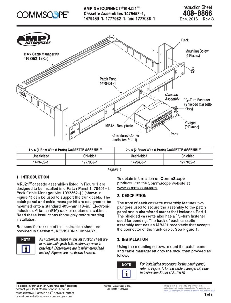
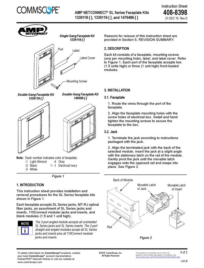
CommScope AMP NETCONNECT 1711357-1 User manual

Instruction Sheet
411-93008
9-JAN-17 Rev B
AMP NETCONNECT® : IP 44
OUTLET SHIELDED DUAL.
1 of 4
LOC IK
Figure 1 /Abbildung 1 Figure 2 /Abbildung 2 Figure 3 /Abbildung 3
2. PRODUCT DESCRIPTION / PRODUKT BESCHREIBUNG.
PN Description / Beschreibung
1711357-1 IP 44 Outlet Shielded Dual
ENGLISH
1. INTRODUCTION.
This Instruction sheet describes termination
procedures for IP 44 Outlet Shielded Dual. The
kit includes the AMP NETCONNECT® Cat.
6 DIN Telecommunications Outlet -
TWIST-6S*, Floor 2 Ports (fig.3), and the
enclosure protection type IP44 (fig. 1).
The connector accepts twisted-pair cable with
conductor range from ∅0.50mm. to 0.65mm.
(AWG 24 to 22, solid conductors). The
acceptable wire insulation range is from ∅0.8mm
to 1.6mm with cable jacket outer diameter of 5
mm to 10mm.
National and local earthing (grounding) bonding
and EMC regulations and procedures shall be
followed.
For other appropriate cable please contact
your local CommScope sales office.
For further information please see the
appropriate customer drawing.
DEUTSCH
1. EINFÜHRUNG.
Diese Installationsanleitung beschreibt den
korrekten Zusammenbau der Doppel-
Datendose IP 44 geschirmt. Das Kit beinhaltet
die AMP NETCNNECT® Cat.6 DIN
Doppeldose TWIST-6S FLOOR und das IP 44
Schutzgehäuse.
Die Datendose ist für Twisted-Pair Kabel mit
einem Leiterquerschnitt von 0,5mm bis 0,65
geeignet (AWG 24 bis 22). Der Aderquerschnitt
über Isolation muss zwischen 0,8 und 1,6 mm
liegen. Der Kabeldurchmesser darf zwischen 5
und 10 mm liegen.
Nationale Regeln zur Erdung und dem Schutz
vor EMV sollten befolgt werden.
Für geeignete Kabel kontaktieren Sie bitte Ihr
lokales CommScope Büro.
NOTE:
All dimensions are in millimeters. Figures are not drawn to scale.
Keep wire pairs twisted to within 6.0 mm (requirement for Cat. 6
applications).
BEMERKUNG:
Alle Abmessungen sind in Millimeter. Abbildungen sind nicht
maßstabsgetreu. Die Verdrillung der Aderpaare nicht mehr als
6,0 mm öffnen (Anforderung an Kat.6 Applikationen).
© 2017 CommScope, Inc.
All Rights Reserved
This product is covered by one or more U.S.
patents or their foreign equivalents. For patents, see
www.commscope.com/ProductPatent/ProductPatent.aspx
To obtain information on CommScope® products, visit our website at
http://www.commscope.com/SupportCenter/TechnicalSupport.aspx
411-93008
Rev B
2 of 4
INGF-033
3. CABLE PREPARATION. Steps per each type of cable.
Cable type: F/UTP; Figure 4 Cable type: F/FTP (Compact); Figure 5
(E): 1. Strip cable jacket back minimum 100 mm.
2. Cut foil partially leaving 10 mm length and fold it back over
cable jacket.
3. Wrap drain wire (if exists) around metal foil (minimum
360º).
4. Remove transparent protection wrap.
- - - - - - - - -
(D):1. Entfernen Sie den Kabelmantel auf mindestens 100 mm Länge.
2. Entfernen Sie teileweise die Folie bis auf 10 mm und falten Sie die
verbleibende Folie über den Kabelmantel
3. Wickeln Sie den Beilaufdraht um die Metallfolie (mindestens 360°)
4. Entfernen Sie die transparente Aderschutzfolie
(E): 1. Strip cable jacket back minimum 100 mm.
2. Cut external foil partially leaving 10 mm length and fold it
back over the cable jacket.
3. Remove the pair foils as shown in figure 4.4. Be aware that
you get maximum performance if you let foils end as close as
possible to the IDC blocks.
--------
(D):1. Entfernen Sie den Kabelmantel auf mindestens 100 mm
Länge.
2. Falten Sie die äussere Metallfolie über den Kabelmantel und
schneiden Sie die Folie nach 10 mm Länge ab.
3. Schneiden Sie die Paarfolien entsprechend Bild 4.4 zu. Bitte
beachten Sie, dass die Folie so nahe wie möglich an die IDC Blöcke
reichen muss um maximale Performance zu erreichen.
Cable type: SF/UTP; Figure 6 Cable type: S/FTP; Figure 7
(E): 1. Strip cable jacket back minimum 100mm.
2. Fold metal braid back over jacket at 10 mm.
3. Cut metal foil to 10mm and fold it back over the braid on the
cable jacked.
4. Remove transparent protection wrap.
- - - - - - - -
(D): 1. Entfernen Sie den Kabelmantel auf mindestens 100 mm
Länge.
2. Falten Sie den Geflechtschirm über den Kabelmantel, dass
mindestens 10 mm Kabelmantel bedeckt sind.
3. Kürzen Sie die Metallfolie auf 10mm und falten diese über den
Geflechtschirm auf dem Kabelmantel. Achtung: Beilaufdraht nicht
entfernen.
Wickeln Sie den Beilaufdraht um den Geflechtschirm (mindestens
360°).
4. Entfernen Sie die Aderschutzfolie.
1. Strip cable jacket back minimum 100 mm.
2. Fold metal braid back over jacket leaving 10 mm.
3. Drain wire (if exists) should be wrapped over the braid of
the cable jacked.
4. Remove the pair foils as shown in figure 4.4. Be aware that
you get maximum performance if you let foils end as close as
possible to the IDC blocks.
---------
(D): 1. Entfernen Sie den Kabelmantel auf mindestens 100 mm
Länge.
2. Falten Sie den Geflechtschirm über den Kabelmantel, dass
mindestens 10 mm Kabelmantel bedeckt sind.
3. Beilaufdraht (wenn vorhanden) um den Geflechtschirm auf
Kabelmantel wickeln
4. Schneiden Sie die Paarfolien entsprechend Bild 4.4 zu. Bitte
beachten Sie, dass die Folie so nahe wie möglich an die IDC Blöcke
reichen muss um maximale Performance zu erreichen.
1
2
3
4
Min. 100
Drain wire
External Foil
10
Clear wrap
Foil + drain
wire
11
22
33
44
Min. 100
Drain wire
External Foil
10
Clear wrap
Foil + drain
wire
1
2
3
4
Min. 100
Drain wire
Ext. Foil
10
Clear wrap
Metal braid
Foil + metal
braid+ drain wire
11
22
33
44
Min. 100
Drain wire
Ext. Foil
10
Clear wrap
Metal braid
Foil + metal
braid+ drain wire
Min. 100 1
2
3
Drain wire
10
Metal braid
Metal braid + drain wire
Pairs in
metal
foil
Min. 100 11
22
33
Drain wire
10
Metal braid
Metal braid + drain wire
Pairs in
metal
foil
1
2
Min. 100
Pairs in
metal
foil
10
External foil
External foil
11
22
Min. 100
Pairs in
metal
foil
10
External foil
External foil
411-93008
Rev B
3 of 4
INGF-033
4. CABLE PREPARATION, ASSEMBLY INSTRUCTION, AND ENVIRONMENT APPLICATION.
/KABELVORBEREITUNG, VERARBEITUNGSANWEISUNGEN UND EINBAUSITUATIONEN.
(E): Open the IP44 enclosure and extract the
outlet.
(D): Öffnen Sie das IP 44 Schützgehäuse.
(E): Put cables through protective membrane
and guide cables into the housing.
(D): Drücken Sie die Kabel durch die
Schutzmembrane und führen die Kabel in das
Gehäuse
(E): Remove the metal cover (outlet) by
removing retaining screw.
(D): Öffnen Sie die Abdeckung der Datendose
durch Öffnen der Schraube.
(E): Recommended length for foil and braid
are shown. Right and left indicated left and
right RJ-45 port.
(D): Empfohlene Längen der Schirmfolien und
Geflechte wie abgedruckt. Rechts und Links sind
die Bezeichungen der RJ-45 Ports.
(E): Open both screws and lift the cable clamp.
(D): Lösen Sie die Schrauben und ziehen Sie die
Kabelklammer leicht nach oben. (E): Place the prepared cables on the outlet.
The positions of the cable braid and the foils
have to be as shown.
(D): Führen Sie die vorbereiteten Kabel in die
Datendose. Die korrekte Positionierung der
Folie und des Geflechtes ist abgebildet.
Metal braid
over jacket
Foils
Cable
Clamp
Metal braid
over jacket
Foils
Cable
Clamp
94 95 96
NOTE:
Be careful when cutting the cable jacket in order to avoid
damaging the PiMF
BEMERKUNG:
Beim Entfernen des Kabelmantels darauf achten, dass die PiMF-
Schirmung nicht beschädigt wird.
NOTE:
Cable type: F/FTP: (PiMF Compact). Under the cable jacket
there is a foil screen instead of a metal braid. The cable
preparation process is the same that for S/FTP (PiMF) cable but
using the foil screen instead of the metal braid. Important: When
fold back the foil screen, the non conductive surface have to be in
contact with cable jacket and the conductive surface have to be
visible.
BEMERKUNG:
Kabeltyp F/FTP und PiMF Compact. Unter dem Kabelmantel
befindet sich ein Folienschirm anstelle eines Geflechtschirmes.
Die Kabelvorbereitung ist die gleiche wie für S/FTP (PiMF)
Kabel jedoch mit Verwendung des Folienschirmes anstelle des
Geflechtes. Wichtig: Beim Umfalten der Folie darauf achten,
dass die isolierte Seite auf dem Kabelmantel und die
kontaktierense Seite nach aussen zeigt.
91 92 93
10 10
Cable Jacket 19
10 10
Cable Jacket 19
10 10
Cable Jacket 19
10 10
Cable Jacket 19
411-93008
Rev B
4 of 4
INGF-033
(E): Choose colour coding acc. TIA 568 A or
B (has to be the same as used on the other side
of the link).
(D): Wählen Sie die Farbcodierung nach TIA
568 A oder B (muss identisch mit der Gegenseite
sein!)
(E): If only one cable exit is required, use the
anti-balance holder, PN 1711081-1. Order
separately (It is not included in the kit)
(D): Sollten Sie die Dose nur mit einem Kabel
beschalten, verwenden Sie bitte das
Ausgleichselemet PN 1711081-1. Separates Teil
nicht im Kit enthalten.
(E): If two cables are required, place them
…and screw cable and screw clamps in.
(D): Legen Sie die Adern zu den IDC Blöcken
und ziehen Sie die Schrauben zur Zugentlastung
und Schirmung handfest an.
(E): Before crimping process, the foil of each
pair has to be as close as possible to the IDC
block. (as shows picture)
(D): Bevor Sie die Adern terminieren, achten Sie
darauf, dass die Paarschirme (wenn vorhanden) so
nahe wie möglich an den IDC Block geführt werden.
(E): Type 110 impact too (A): PN 569994-1,
346859-1 or 1375308-1. LSA-Plus (#) or
PN 3-1199209-6 (B).
(D): Erlaubte Werkzeuge: Typ 110 (A)
PN 569994-1, 346859-1, 1375308-1 oder
baugleich oder LSA+ (B) PN 3-1199209-6.
(E): Crimp the wires with the appropriate tool,
according to colour coding required.
(D): Terminieren Sie die Adern mit einem
geeigneten Werkzeug gemäss gewähltem
Farbcode.
(E): Keeping the foils as shown on picture.
(D): Die Aderschirmung (wenn vorhanden)
sollte wie abgebildet sein.
(E): Place and press the cover against the
housing to ensure correct fitting. Screw the
locking screw in. Ready to install.
(D): Schliessen Sie den Deckel und drücken Sie
diesen gegen das Gehäuse. Ziehen Sie die
Gehäuseschraube an. Fertig zum Einbau!
(E): Fix the bottom enclosure to the wall and
the frame adapter to the bottom enclosure.
(D): Fixieren Sie das Schutzgehäuse an der
Wand und befestigen Sie den Adapterrahmen am
Unterteil.
(E): Fix the outlet to the bottom enclosure by
tightening the 2 retaining screws (as shown).
(D): Fixieren Sie die Datendose am
Gehäuseunterteil durch Anziehen der beiden
Schrauben (siehe Abbildung).
(E): Place and screw the cover frame in (as
shown).
(D): Plazieren und fixieren Sie das IP-44
Gehäuse wie abgebildet.
(E): Place the label cover with the paper strip
identifying the outlet.
(D): Beschriften Sie die Datendose wenn
gewünscht mit beiligendem Papierstreifen.
Anti-balance holderCable Anti-balance holderCable
ICD Block
Pair’s Foil
ICD Block
Pair’s Foil 2020
AA AA BB
AA AA BB
20202020
AAAA AAAA BBBB
AAAA AAAA BBBB
97 99
9
13 9
14 9
15
9
16 9
17
98
9
18
9
10 9
11 9
12

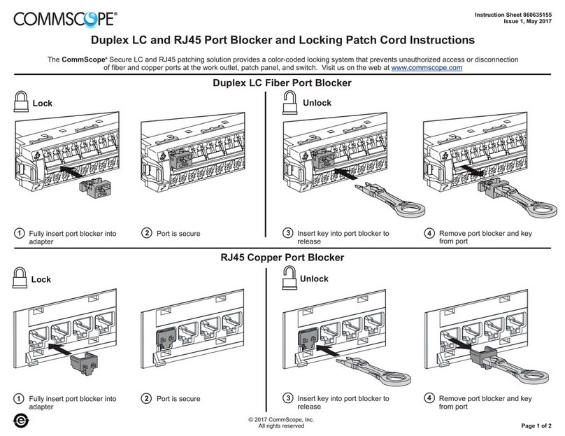
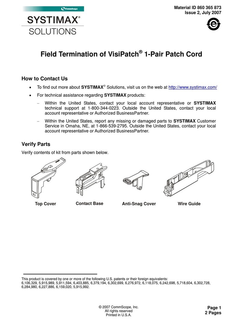
Other CommScope Cables And Connectors manuals

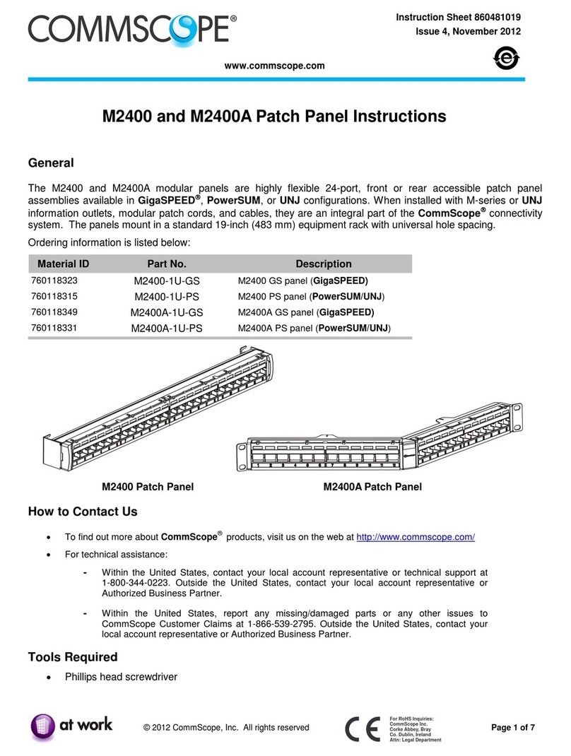
CommScope SYSTIMAX 360 iPatch 360-iP-G2-1U-LC-FX User manual

CommScope

CommScope SYSTIMAX 360 iPatch 360-iP-G2-1U-LC-FX User manual

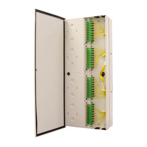
CommScope FOSC-350C User manual

CommScope

CommScope FOSC-350C User manual

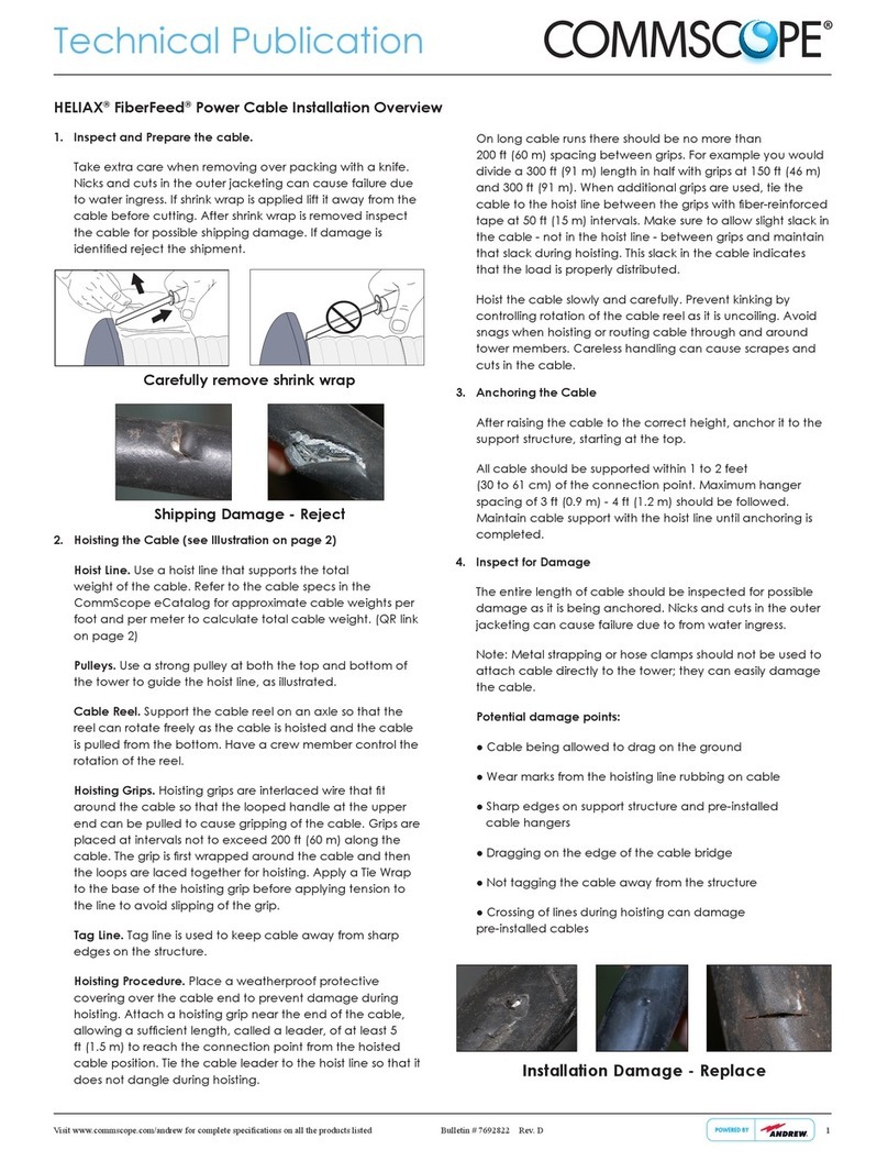
CommScope HELIAX FiberFeed HFE810 Series Instruction sheet

CommScope

CommScope HELIAX FiberFeed HFE810 Series Instruction sheet

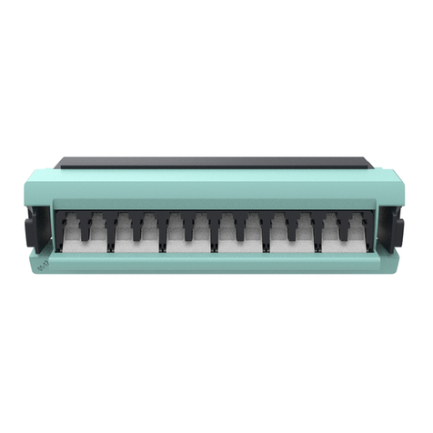
CommScope LC User manual

CommScope

CommScope LC User manual

CommScope ETHERSEAL 1479563-2 User manual

CommScope

CommScope ETHERSEAL 1479563-2 User manual

CommScope HELIAX FiberFeed FDH1206-12M50 Series Instruction sheet

CommScope

CommScope HELIAX FiberFeed FDH1206-12M50 Series Instruction sheet

CommScope LightCrimp Plus ST User manual

CommScope

CommScope LightCrimp Plus ST User manual

CommScope HELIAX FiberFeed HTC1006 Series Instruction sheet

CommScope

CommScope HELIAX FiberFeed HTC1006 Series Instruction sheet

CommScope SYSTIMAX 360 760150144 User manual

CommScope

CommScope SYSTIMAX 360 760150144 User manual

CommScope SYSTIMAX 360 iPatch PATCHMAX User manual

CommScope

CommScope SYSTIMAX 360 iPatch PATCHMAX User manual

CommScope FD21206-48SRC Series Instruction sheet

CommScope

CommScope FD21206-48SRC Series Instruction sheet

CommScope LC User manual

CommScope

CommScope LC User manual

CommScope NOVUX SEC 100 User manual

CommScope

CommScope NOVUX SEC 100 User manual

CommScope FOSC-400BG User manual

CommScope

CommScope FOSC-400BG User manual

CommScope HELIAX FiberFeed HFT1206-24S49 Series Instruction sheet

CommScope

CommScope HELIAX FiberFeed HFT1206-24S49 Series Instruction sheet

CommScope HELIAX FiberFeed HFA208 Series Instruction sheet

CommScope

CommScope HELIAX FiberFeed HFA208 Series Instruction sheet

CommScope SYSTIMAX 360 iPatch... User manual

CommScope

CommScope SYSTIMAX 360 iPatch... User manual

CommScope FOSC450 C User manual

CommScope

CommScope FOSC450 C User manual

CommScope FOSC-450D User manual

CommScope

CommScope FOSC-450D User manual

CommScope AMP NETCONNECT 1933352 Series User manual

CommScope

CommScope AMP NETCONNECT 1933352 Series User manual

CommScope AMP NETCONNECT 553454-1 User manual

CommScope

CommScope AMP NETCONNECT 553454-1 User manual

CommScope FIST-RSKG-16 User manual

CommScope

CommScope FIST-RSKG-16 User manual

CommScope NOVUX User manual

CommScope

CommScope NOVUX User manual

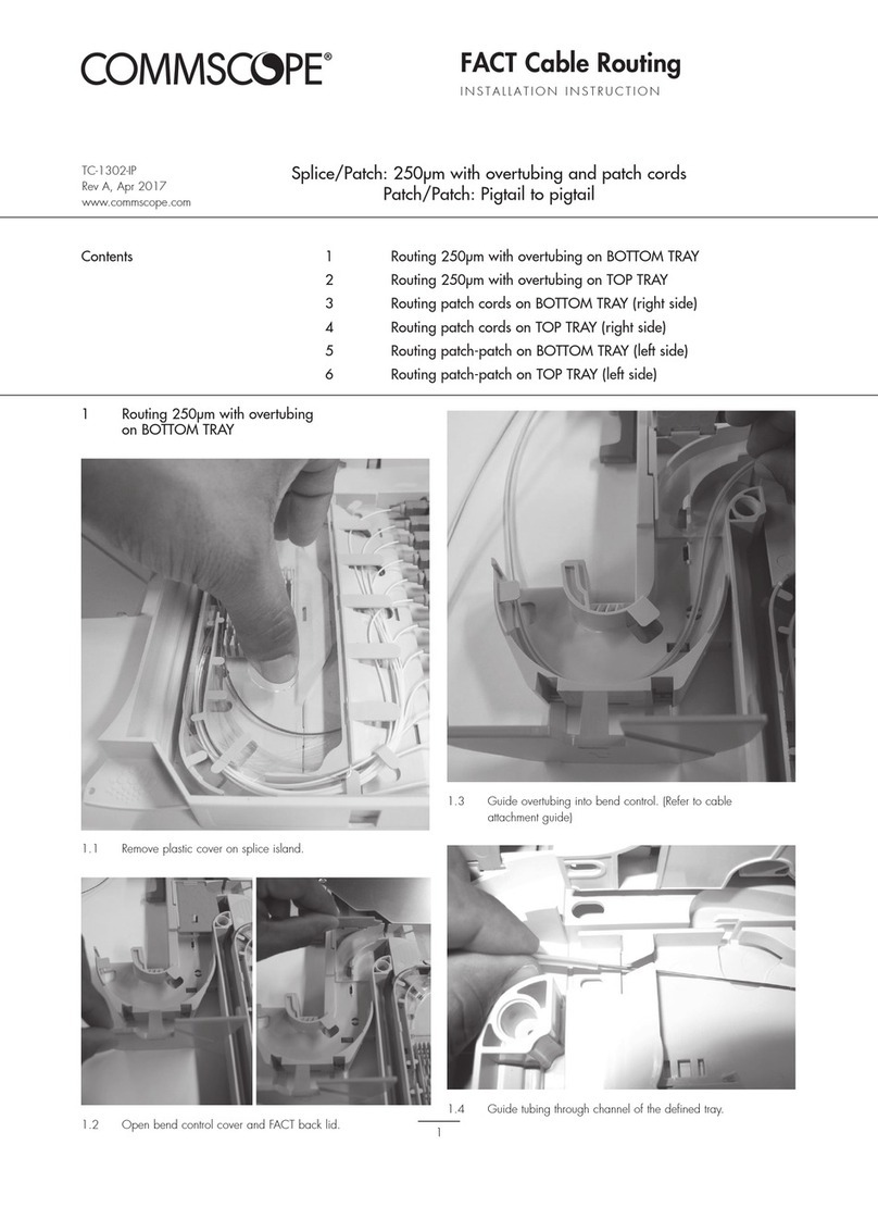
CommScope FACT User manual

CommScope

CommScope FACT User manual

Popular Cables And Connectors manuals by other brands

ELBOX nSplitter Pro 1x2 MK-II DE/QS user manual

ELBOX

ELBOX nSplitter Pro 1x2 MK-II DE/QS user manual

Targus High Speed File Share Cable user guide

Targus

Targus High Speed File Share Cable user guide

AKG PS 3 F-LOCK quick start guide

AKG

AKG PS 3 F-LOCK quick start guide

Burndy Continental Industries thermOweld CC-14 instructions

Burndy

Burndy Continental Industries thermOweld CC-14 instructions

Akyga AK-EC-02 user manual

Akyga

Akyga AK-EC-02 user manual

Advanced Bionics Naida Cl CI-5415 Instructions for use

Advanced Bionics

Advanced Bionics Naida Cl CI-5415 Instructions for use

Amiga S-Video installation manual

Amiga

Amiga S-Video installation manual

Mobile MB-1010 user guide

Mobile

Mobile MB-1010 user guide

Tripp Lite Computer Display Cable P560-020 Specifications

Tripp Lite

Tripp Lite Computer Display Cable P560-020 Specifications

Herman Miller Canvas Office Landscape FW140.08 Series Installation and Disassembly for Recycling Instructions

Herman Miller

Herman Miller Canvas Office Landscape FW140.08 Series Installation and Disassembly for Recycling Instructions

C-me U6MIDI Pro user manual

C-me

C-me U6MIDI Pro user manual

Inakustik AC-1502-P6 Operation manual

Inakustik

Inakustik AC-1502-P6 Operation manual

Tripp Lite N352-09M Specification sheet

Tripp Lite

Tripp Lite N352-09M Specification sheet

Tripp Lite N001-015-GY Specification sheet

Tripp Lite

Tripp Lite N001-015-GY Specification sheet

Digital Zone HDMI 412L user manual

Digital Zone

Digital Zone HDMI 412L user manual

Tripp Lite EZB-DVIF-2 Specification sheet

Tripp Lite

Tripp Lite EZB-DVIF-2 Specification sheet

Black Box VSP-HDMI2-1X4 user manual

Black Box

Black Box VSP-HDMI2-1X4 user manual

Tripp Lite N001-050-BL Specification sheet

Tripp Lite

Tripp Lite N001-050-BL Specification sheet

manuals.online logo
manuals.online logoBrands
  • About & Mission
  • Contact us
  • Privacy Policy
  • Terms and Conditions

Copyright 2025 Manuals.Online. All Rights Reserved.