408- 4457
Rev J
8of 16
DO NOT attempt to clean the ber after it has
been cleaved.
C. Crimping (Figures 9, 10,and 11)
1. Open the cable clamp of the cableholder, and
hold the buer (with the cleaved end of the ber
facing the connector) inside the clamp. Pull the end
of the ber even with the front of the arm of the
cableholder, andholding the buer in place, close
the clamp. See Figure 9, Detail A.
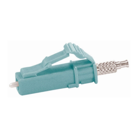
2. Carefullyinsert the berinto the plunger of the
connector assemblyuntil the the berbottoms
against the internal ber. Make sure that the
remaining mark on the buer enters the plunger.
The resultantbend in the buer shouldhold the
beragainst the internal ber. See Figure 9,
Detail B.
It is important that the berbottoms against, and
remains against, the internal ber. If the mark
doesnotenter the plunger or if the berdoesnot
seem to bottom against the internal ber, the
ber may be caught on internalguides. Rotating
the connector andbacking the berout a small
amountand re--entering may help. However, if
the mark willnotenter the plunger, the ber must
be re--stripped.
Make sure that the berdoesnotpull rearward
from the contact (with the internal ber) during
the crimping operation.
3. Squeeze the handles of the hand tooluntil the
ratchet releases. Allow the handles to open fully.
Gently close the handlesuntil you hear three clicks
from the ratchet.
4. With the connector assembly in the cable
holder, position the ferrule protective cover in the
upper cavity of the frontdieand the plunger in the
upper cavity of the reardie. It is importantto make
sure that the tip of the plunger sits in the channel
of the reardiewith the protrudingdisk of the
plungerat against the wall of the cavity. If the
plungerisnotpositioned correctly, it will be
crushedwhen the tool is actuated. See Figure 9,
Detail C.
The arrows marked on the front die indicate the
direction that the ferrule protective cover must be
pointing when the connector is positioned in that
cavity. For proper placement, andtoavoid
damage to the ber, the direction of the arrows
must be observed. Refer to Figure 9, Detail C
and Figure 10, Detail A.
5. Gently push the buer toward the connector to
make sure that the ber is stillbottomed, then
slowly squeeze the toolhandles togetheruntil the
ratchet releases. Allow the handles to open fully,
and remove the connector assembly from the dies.
6. Position the plunger of the connector assembly
in the rst (smallest) cavity of the frontdiewith the
shoulder of the plungeragainst the edge of the
groove in the dieand the ferrule protective cover
pointing in the direction of the arrow. See Figure
10,Detail A.
7. Slowly squeeze the toolhandles togetheruntil
the ratchet releases. Allow the handles to open
fully, and remove the connector assembly from the
die.
8. Slide the crimp eyeletaway from the connector
until the strength members are free, then slide the
crimp eyelet toward the connector until the strength
members and crimp eyeletbutt against the
connector. See Figure 10,Detail B.
For 2.0 -- to 2.4--mm jacketed cable, slide the black
tube forward into the smalldiameter end of the
crimp eyeletuntil it buttsagainst the rear of the
connector.
9. Position the large diameter end of the crimp
eyelet in the last (largest) cavity of the frontdie
with the ferrule protective cover pointing in the
direction of the arrow. See Figure 11, Detail A.
Slowly squeeze the toolhandles togetheruntil the
ratchet releases. Allow the handles to open fully.
10. Position the smalldiameter end of the crimp
eyelet in the middle cavity of the frontdiewith the
ferrule protective cover pointing in the direction of
the arrow. See Figure 11, Detail B.
11. Slowly squeeze the toolhandles togetheruntil
the ratchet releases. Allow the handles to open
fully, and remove the connector assembly from the
die.
12. Open the cable clamp of the cableholder, and
remove the cable from the clamp. Slide the strain
relief over the plungeruntil the strain reliefbutts
against the connector. See Figure 11, Detail C.
13.Remove the connector assembly from the
cableholder.
The assemblyprocedure for 2.0-- to 3.0--mm jacketed
cable is now complete.
"If connecting connectors, inspect the ferruleend
face for cleanliness using200¢Microscope Kit
1754767--1 (includes 2.5--mm adapter cap).
CAUTION
!
NOTE
i
CAUTION
!
