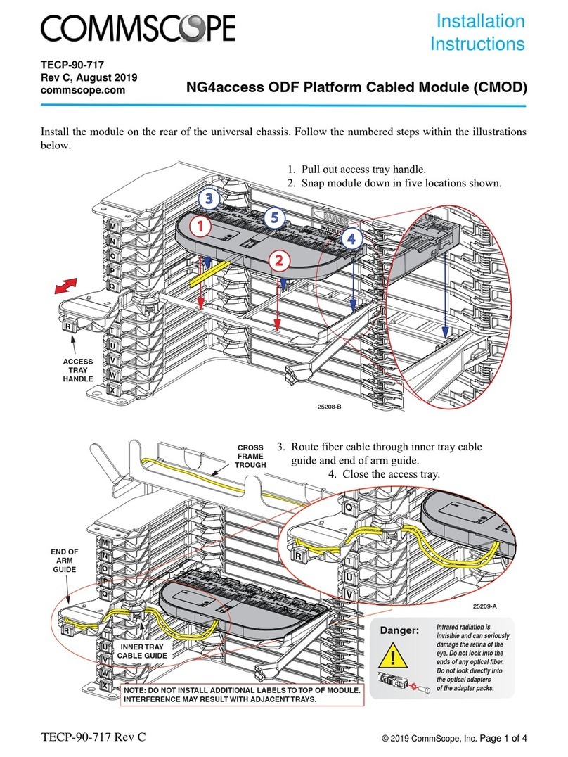
Figure 7. Example Of One Set-Up Using The ABSBT-4G Series
Smart Bias Tees In A RET System.
Antenna
Coax Jumper Cable
Male Coaxial
Connector
ATSBT-
TOP-FF-4G
Male AISG
Connector
Actuator
Female AISG
Connector
RET Control
Cable
Male
Coaxial
Connector
Coax Feeder Cable
Female
Coaxial
Connector
ATSBT-
BOTTOM-FM-4G
Male Coaxial Connector
Coax Jumper Connector
RET Control
Cable
Female AISG
Connector
To Controller
Bolt
Lockwasher
Flatwasher
Spacer
Grounding
Cable (Not
Supplied)
Grounding Cable
(Not Supplied)
Flat Washer
Split Flat
Washer
Hex HD Bolt
Grounding
Cable
Spacer
Additional Product:
• The ATGK-COMP Grounding Kit
is used to ground the Smart Bias
Tee and is sold separately.
Figure 8. ATGK-COMP Grounding Kit.
BTS
TOP UNIT INSTALLATION INSTRUCTIONS
INSTALLATION PROCEDURE
BOTTOM UNIT INSTALLATION INSTRUCTIONS
4. Connect a bottom Smart Bias Tee on the same coaxial
feeder cable as the top bias tee or AISG TMA.
5. Connect the lower coaxial connector on the Smart Bias
Tee to the BTS with a coaxial jumper cable.
6. Attach the female end of the RET control cable to the
Smart Bias Tee, and the male end to the controller.
(See caution above.)
Note that the label on the Smart Bias Tee includes a diagram to
guide proper installation.
POST INSTALLATION INSTRUCTIONS
These steps apply after top and bottom units are in place:
7. a) Carefully tighten DIN connections until they are snug,
but do not apply heavy force with pliers.
b) Weatherproof the DIN connections, carefully covering
all junctions and the outer jacket of the cable.
8. a) Remove bolt, washers, and spacer from the Smart
Bias Tee ground (supplied).
b) Connect ATGK-COMP ground cable (not supplied) to
Smart Bias Tee, as needed.
c) Reattach bolt and washers to secure the cable.
9. Attach ground cable to tower ground with M10 x 25mm
bolts, nuts, and washers (provided with ATGK-COMP kit)
or with other appropriate hardware (Figure 8).
10. Use cable tie to fix the Smart Bias Tee properly to avoid the
connector loose by vibration.
After installation of Smart Bias Tee units is complete, connect the
remaining Teletilt system components according to their respective
installation instructions (Figure 9).
After all system components are installed, connect the RET line to
the controller and verify successful operation. Refer to Table 1,
Troubleshooting When Power Is Not Provided To Tower Top, if
needed.
(continued on page 5)
b) Depending on the RET cable length, CommScope
recommends forming a loop in the cable as shown
below in step 3 of Figure 7. Next attach the male
end of the RET control cable to the Smart Bias Tee
and the female end to the actuator.
c) With the AISG connector at the bottom of the Smart
Bias Tee, the RET cable should hang down so water
drains away from the connector.
Install top and bottom ATSBT-4G Series Smart Bias Tees by
following steps 1 through 9, detailed in Figure 7.
www.commscope.com
© 2021 CommScope, Inc. All rights reserved.
Visit our website at www.commscope.com or contact your local CommScope representative or BusinessPartner for more information.
All trademarks identified by ® or ™ are registered trademarks or trademarks, respectively, of CommScope, Inc. 653102 G (5/26)
Page 4 of 5
653102
