manuals.online logo
Brands
  1. Home
  2. •
  3. Brands
  4. •
  5. Comnet
  6. •
  7. Transmitter
  8. •
  9. Comnet FVT801 User manual

Comnet FVT801 User manual

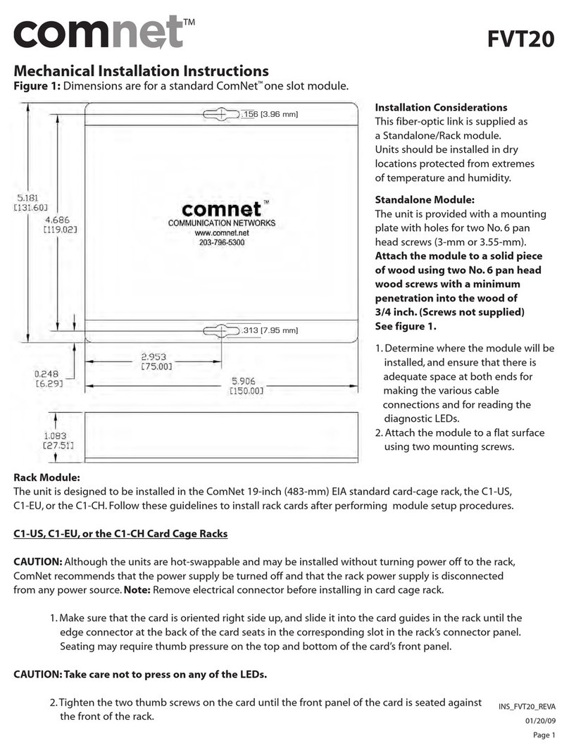
Mechanical Installation Instructions
Figure 1– Dimensions are for a standard ComNet™ one slot module.
Rack Module:
The unit is designed to be installed in the ComNet 19-inch (483-mm) EIA standard card-cage rack, the C1-US,
C1-EU, or the C1-CH. Follow these guidelines to install rack cards after performing module setup procedures.
C1-US, C1-EU, or the C1-CH Card Cage Racks
CAUTION: Although the units are hot-swappable and may be installed without turning power off to the rack, ComNet
recommends that the power supply be turned off and that the rack power supply is disconnected from any power
source. Note: Remove electrical connector before installing in card cage rack.
1. Make sure that the card is oriented right side up, and slide it into the card guides in the rack until the edge
connector at the back of the card seats in the corresponding slot in the rack’s connector panel. Seating may
require thumb pressure on the top and bottom of the card’s front panel.
CAUTION: Take care not to press on any of the LEDs.
2. Tighten the two thumb screws on the card until the front panel of the card is seated against the front of the rack.
FVT/FVR801
Installation Considerations
This fiber-optic link is supplied as a
Standalone/Rack module. Units should be
installed in dry locations protected from
extremes of temperature and humidity.
Standalone Module:
The unit is provided with a mounting
plate with holes for two No. 6 pan head
screws (3-mm or 3.55-mm).
Attach the module to a solid piece of
wood using two No. 6 pan head wood
screws with a minimum penetration
into the wood of 3/4 inch. (Screws not
supplied) See figure 1.
1. Determine where the module will
be installed, and ensure that there
is adequate space at both ends for
making the various cable connections
and for reading the diagnostic LEDs.
2. Attach the module to a flat surface
using two mounting screws.
INS_FVT/FVR801_REV–
08/19/09
Page 1
For Technical Support, Contact Your Nearest Communication Networks Office:
3 Corporate Drive • Danbury, CT 06810 • USA • Tel: 203-796-5300 • Toll Free: 1-888-678-9427 • www.comnet.net
8 Turnberry Park Road • Gildersome • Morley • Leeds, UK LS27 7LE • Tel: +44 (0)113 307 6400 • Fax: +44 (0)113 253 7462
.156 [3.96 mm]
INS_FVT/FVR801_REV–
08/19/09
Page 2
INSTALLATION INSTRUCTIONS
WARNING: Unit is to be used with a Listed Class 2 or LPS power supply rated 9-12 VDC @ 1A.
WARNING: This unit should be installed in a restricted access location; available through the use of a lock and key or other means of security.
Access should be limited to service personnel who have been instructed about the reasons for the restrictions to the location. Any and all pre-
cautions should be taken and controlled by the authority responsible for the location.
IMPORTANT SAFEGUARDS:
A) Elevated Operating Ambient - If installed in a closed or multi-unit rack assembly, the operating ambient temperature of the rack environ-
ment may be greater than room ambient. Therefore, consideration should be given to installing the equipment in an environment compatible
with the maximum ambient temperature (Tma) specified by the manufacturer.
B) Reduced Air Flow - Installation of the equipment in a rack should be such that the amount of air flow required for safe operation of the
equipment is not compromised.
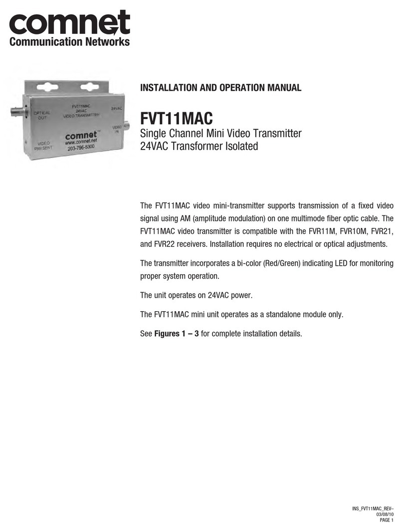
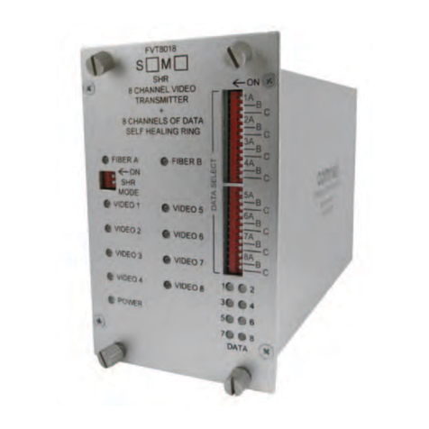
FVT801
8-CHANNEL 10-BIT DIGITAL VIDEO TRANSMITTER
For Technical Support, Contact Your Nearest Communication Networks Office:
3 Corporate Drive • Danbury, CT 06810 • USA • Tel: 203-796-5300 • Toll Free: 1-888-678-9427 • www.comnet.net
8 Turnberry Park Road • Gildersome • Morley • Leeds, UK LS27 7LE • Tel: +44 (0)113 307 6400 • Fax: +44 (0)113 253 7462
BLACK WITH WHITE STRIPE
BLACK
MULTIMODE OR
SINGLE MODE
OPTICAL FIBER
NOTE: Remove Electrical Connector for Rack Mount Units
INS_FVT/FVR801_REV–
08/19/09
Page 3
INSTALLATION INSTRUCTIONS
WARNING: Unit is to be used with a Listed Class 2 or LPS power supply rated 9-12 VDC @ 1A.
WARNING: This unit should be installed in a restricted access location; available through the use of a lock and key or other means of security.
Access should be limited to service personnel who have been instructed about the reasons for the restrictions to the location. Any and all pre-
cautions should be taken and controlled by the authority responsible for the location.
IMPORTANT SAFEGUARDS:
A) Elevated Operating Ambient - If installed in a closed or multi-unit rack assembly, the operating ambient temperature of the rack environ-
ment may be greater than room ambient. Therefore, consideration should be given to installing the equipment in an environment compatible
with the maximum ambient temperature (Tma) specified by the manufacturer.
B) Reduced Air Flow - Installation of the equipment in a rack should be such that the amount of air flow required for safe operation of the
equipment is not compromised.
FVR801
8-CHANNEL 10-BIT DIGITAL VIDEO RECEIVER
For Technical Support, Contact Your Nearest Communication Networks Office:
3 Corporate Drive • Danbury, CT 06810 • USA • Tel: 203-796-5300 • Toll Free: 1-888-678-9427 • www.comnet.net
8 Turnberry Park Road • Gildersome • Morley • Leeds, UK LS27 7LE • Tel: +44 (0)113 307 6400 • Fax: +44 (0)113 253 7462
MULTIMODE OR
SINGLE MODE
OPTICAL FIBER
BLACK WITH WHITE STRIPE
BLACK
NOTE: Remove Electrical Connector for Rack Mount Units
INS_FVT/FVR801_REV–
08/19/09
Page 4
FVT/FVR801
8-CHANNEL 10-BIT DIGITAL VIDEO
For Technical Support, Contact Your Nearest Communication Networks Office:
3 Corporate Drive • Danbury, CT 06810 • USA • Tel: 203-796-5300 • Toll Free: 1-888-678-9427 • www.comnet.net
8 Turnberry Park Road • Gildersome • Morley • Leeds, UK LS27 7LE • Tel: +44 (0)113 307 6400 • Fax: +44 (0)113 253 7462
LED INDICATORS
LINK VIDEO POWER
GREEN Communication link has An active video signal is Unit powered up
been established over present on the BNC
optical fiber connector.
RED Communication link has No video signal –
not been established.
OFF Not powered up correctly – Unit powered down

This manual suits for next models

1

Other Comnet Transmitter manuals

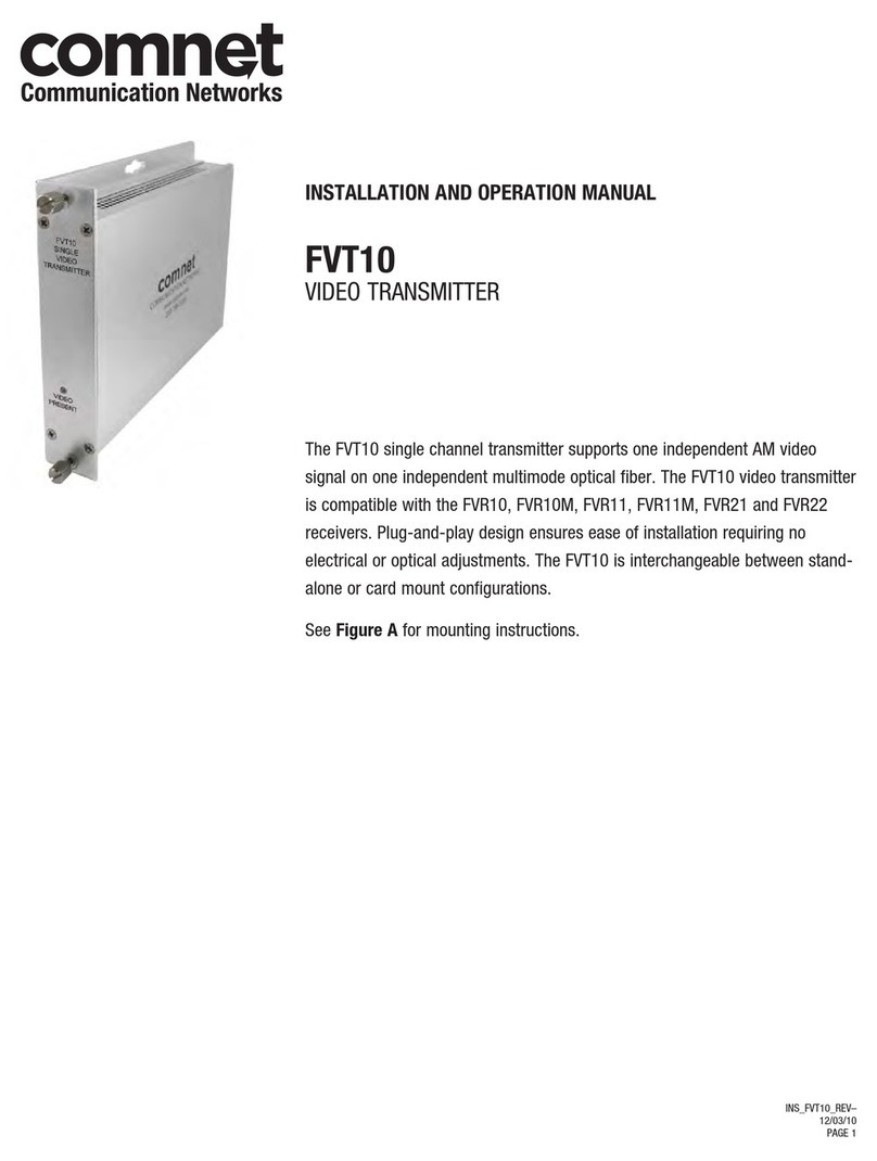
Comnet FVT10 User manual

Comnet

Comnet FVT10 User manual

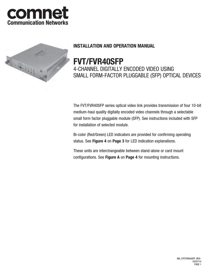
Comnet FVT40SFP Series User manual

Comnet

Comnet FVT40SFP Series User manual

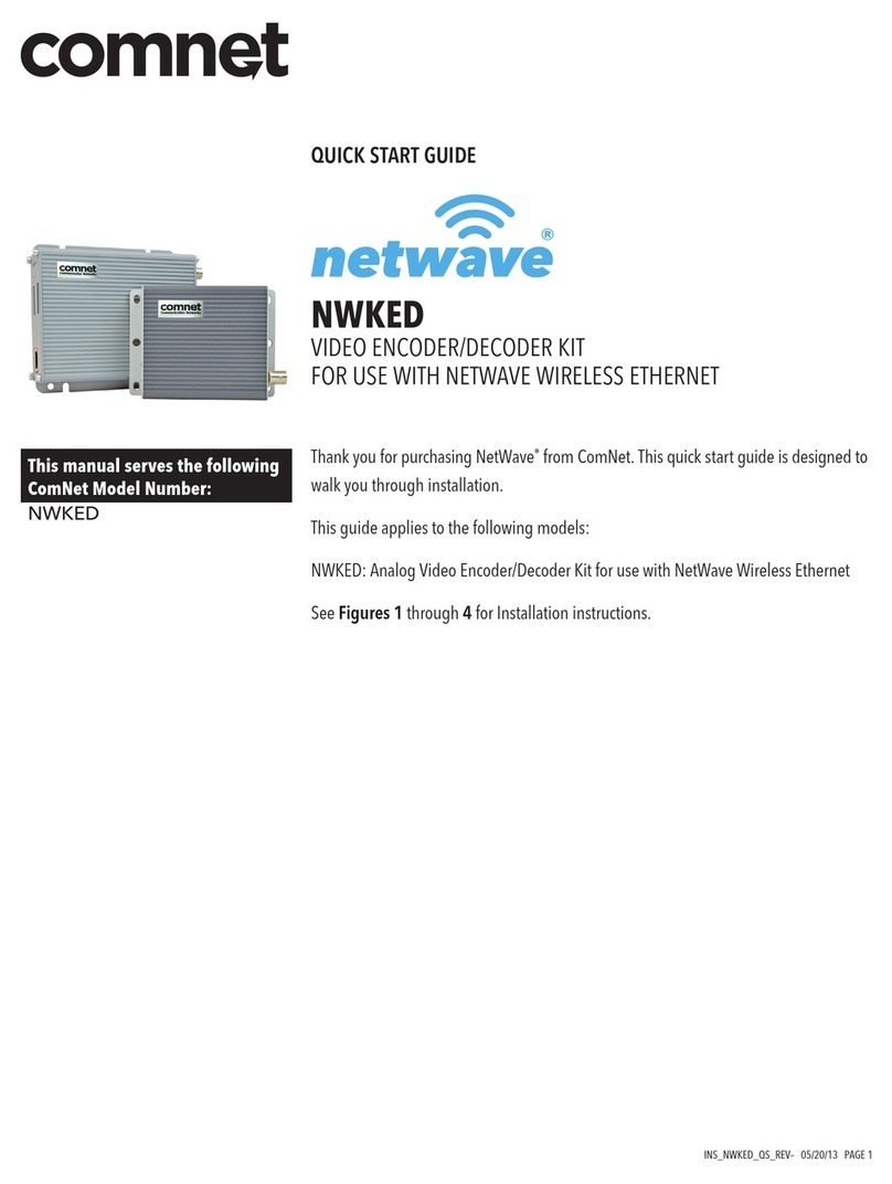
Comnet netwave NWKED User manual

Comnet

Comnet netwave NWKED User manual
Comnet FDC8ISOT1 User manual

Comnet

Comnet FDC8ISOT1 User manual

Comnet FVT1C1BM1-M User manual

Comnet

Comnet FVT1C1BM1-M User manual

Comnet FVT11MAC User manual

Comnet

Comnet FVT11MAC User manual

Comnet FVT8014 User manual

Comnet

Comnet FVT8014 User manual

Comnet FVT4014SHR User manual

Comnet

Comnet FVT4014SHR User manual

Comnet FVTR1D1A2C1M1 User manual

Comnet

Comnet FVTR1D1A2C1M1 User manual

Comnet FVT80D8SFP User manual

Comnet

Comnet FVT80D8SFP User manual

Comnet FVR1031S1 User manual

Comnet

Comnet FVR1031S1 User manual

Comnet FVT20 User manual

Comnet

Comnet FVT20 User manual
Comnet FVT10C1(M,S)1/M Series User manual

Comnet

Comnet FVT10C1(M,S)1/M Series User manual

Comnet FVR1021 Series User manual

Comnet

Comnet FVR1021 Series User manual

Comnet FVT4014 User manual

Comnet

Comnet FVT4014 User manual

Comnet FVT1031 User manual

Comnet

Comnet FVT1031 User manual
Comnet FVR1031 series Owner's manual

Comnet

Comnet FVR1031 series Owner's manual

Comnet FVT80D4SFP User manual

Comnet

Comnet FVT80D4SFP User manual

Comnet FVTR User manual

Comnet

Comnet FVTR User manual

Popular Transmitter manuals by other brands

Magnetrol Jupiter JM4 Installation and operating manual

Magnetrol

Magnetrol Jupiter JM4 Installation and operating manual

Heystar HS-ZSD14-RF01 Instruction book

Heystar

Heystar HS-ZSD14-RF01 Instruction book

Shure AXT200 instruction manual

Shure

Shure AXT200 instruction manual

Shure ULXD6 user guide

Shure

Shure ULXD6 user guide

Dwyer Instruments 631 Series Installation and operating instructions

Dwyer Instruments

Dwyer Instruments 631 Series Installation and operating instructions

Rotronic HF120 instruction manual

Rotronic

Rotronic HF120 instruction manual

nedis BTRC110BK manual

nedis

nedis BTRC110BK manual

Warner RF FMT5.0-4U Series manual

Warner RF

Warner RF FMT5.0-4U Series manual

NVM NT1001 installation manual

NVM

NVM NT1001 installation manual

Arcam RWAVE quick start guide

Arcam

Arcam RWAVE quick start guide

Emerson Rosemount 2051 Reference manual

Emerson

Emerson Rosemount 2051 Reference manual

PEHA Easyclick FU-BLS 20.450 Series Installation and operating instructions

PEHA

PEHA Easyclick FU-BLS 20.450 Series Installation and operating instructions

Siemens FS-DACT installation instructions

Siemens

Siemens FS-DACT installation instructions

Southland EMD-570 instruction manual

Southland

Southland EMD-570 instruction manual

Extron electronics ExSens instruction manual

Extron electronics

Extron electronics ExSens instruction manual

Williams Sound TGS 863 Manual and user guide

Williams Sound

Williams Sound TGS 863 Manual and user guide

Lectrosonics LMb instruction manual

Lectrosonics

Lectrosonics LMb instruction manual

ADOLF THIES CLIMA 4.3324.32.000 Instructions for use

ADOLF THIES

ADOLF THIES CLIMA 4.3324.32.000 Instructions for use

manuals.online logo
manuals.online logoBrands
  • About & Mission
  • Contact us
  • Privacy Policy
  • Terms and Conditions

Copyright 2025 Manuals.Online. All Rights Reserved.