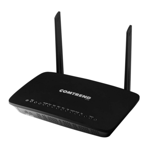
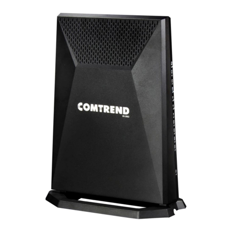
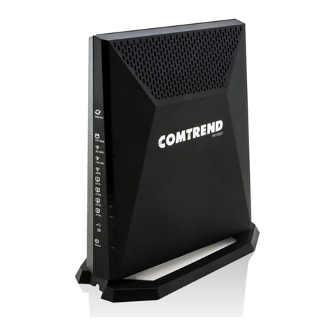
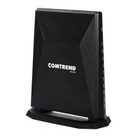
Comtrend Corporation VR-3071 Series User manual

1
Pre face
This m an ual pr ov ides infor m at ion relat ed t o t he inst allat ion and operat ion of th is
device. The individual reading t his m anual is pr esum ed t o have a basic
under standing of telecom m unications t erm inology and concept s.
I f you find the product to be inoperable or m alfunctioning, please contact t echnical
support for im m ediat e service by em ail at I NT- support @com t rend.com
For product update, new product release, m anual revision, or soft ware upgrades,
please visit our website at ht tp: / / www.com t rend.com
I m por t ant Safet y I nst ructions
Wit h r ef er ence t o u npackin g, in st allat ion, u se, and m ain t enan ce of you r elect r onic
device, the following basic guidelines ar e recom m ended:
Do not use or inst all t his product near water, to avoid fire or shock hazard. For
exam ple, near a batht ub, kit chen sink or laundry t ub, or near a swim m ing pool.
Also, do not expose t he equipm ent t o rain or dam p areas ( e.g. a w et basem ent ) .
Do not connect t he power supply cord on elevat ed surfaces. Allow it t o lie fr eely.
There should be no obstruct ions in it s pat h and no heavy it em s should be placed
on t he cord. I n addition, do not walk on, st ep on, or m ist reat the cord.
Use only t he power cord and adapt er t hat are shipped wit h t his device.
Never install t elephone wiring during storm y weather conditions.
CAUTI ON:
Always disconnect all t elephone lines from the wall outlet before servicing
or disassem bling this equipm ent .
Changes or m odificat ions t o t his unit not expressly approved by t he part y
responsible for com pliance could void the user authority t o operat e t he
equipm ent .
Do not stack equipm ent or place equipm ent in t ight spaces, in drawers, or
on carpet s. Be sure t hat your equipm ent is surrounded by at least 2 inches
of air space.
To prevent interference wit h cordless ph ones, ensure t h at t he gat eway is
at least 5 feet ( 1.5m ) fr om t he cordless ph one base st at ion.
I f you experience t rouble wit h this equipm ent , disconnect it from t he
net w ork unt il t he pr oblem has been cor rect ed or u nt il you are sur e t hat
equipm ent is not m alfunct ioning.

2
W ARN I N G
Disconnect t he power line from t he device before servicing
For indoor use only
Do NOT open the casing
Do NOT use near water
Do NOT insert sharp objects int o t he RJ- 11 j ack
Keep away from the fire
For u se in vent ilat ed env iron m ent / space
Use 26 AWG or larger cable connect t o RJ- 1 1 por t
Débranchez l'alim ent at ion électrique avant l'ent ret ien
Cet appareil est conçu pour l'usage intérieur seulem ent
N'ouv rez pas le boît ier
N'utilisez pas cet appareil près de l'eau
N'insérez pas d'obj et s t ranchant s dans la prise RJ- 11
N'approchez pas du feu
Veuillez utiliser dans un environnem ent aéré
Veuillez utiliser fil élect rique de 26AWG pour port RJ- 11
Pow er Specificat ions ( Alim ent at ion ) :
I nput : 12Vdc, 3.0A or 2.0A
Out put : USB3.0, 900m A
Use r I nfor m a t ion
Any changes or m odificat ions not expressly approved by t he part y responsible for
com pliance could void your aut horit y t o operat e t he equipm ent.
Aucune m odificat ion apport ée à l’appareil par l’ut ilisateur, quelle qu’en soit la nature.
Tout changem ent ou m odificat ion peuvent annuler le dr oit d’ut ilisat ion de l’appareil
par l’ut ilisat eur.
N ot e : This equipm ent has been t est ed an d fou nd t o com ply w it h t he lim it s for a
Class B digit al device, pursuant to part 15 of t he FCC Rules. These lim it s ar e
designed to provide reasonable protect ion against h arm ful int erfer ence in a
resident ial inst allat ion. This equipm ent generat es, uses and can radiate radio
fr equency energy an d, if not in st alled and u sed in accordance w it h t he inst r uct ions,
m ay cause harm ful interference t o radio com m unications. However, t here is no
guarant ee t hat int erference will not occur in a part icular inst allat ion. I f this
equipm ent does cause harm ful int er ference to radio or television recept ion, which
can be det erm ined by t urning t he equipm ent off and on, t he user is encouraged to
try t o correct t he int erference by one or m ore of the following m easures:
—Reorient or relocate the receiving antenna.
—I ncrease t he separat ion between t he equipm ent and receiver.
—Connect the equipm ent int o an out let on a circuit different from that t o which the
receiver is connect ed.
—Consult the dealer or an experienced radio/ TV t echnician for help.
This device com plies wit h Part 15 of t he FCC Rules. Operat ion is su bj ect t o t he
follow ing t w o condit ions: ( 1 ) Th is dev ice m ay not cause har m ful in t er ference, and ( 2)
t his device m ust accept any int erference received, including int er ference t hat m ay
cause undesired operat ion.

3
This Class B digit al apparat us com plies w it h Canadian I CES- 003.
To reduce potent ial radio int erference to other users, the ant enna t ype and
it s gain should be so chosen t hat the equivalent isot ropically radiat ed power
( e.i. r. p.) is n ot m ore t han t hat perm it ted for successful com m unicat ion.
This device com plies with Part 15 of the FCC Rules and I ndust ry Canada
licence- exem pt RSS st an dar d( s) .
Operat ion is subj ect t o t h e follow ing t wo condit ions:
1. This device m ay not cause interference, and
2. This dev ice m u st accept any in t er ference, including int erfer ence t hat m ay
cause undesired operat ion of t he dev ice.
Cet appareil num érique de la classe B est conform e à la norm e NMB- 003 Canada.
Pour réduire le risque d’int erférence aux aut res utilisateurs, le type d’antenne
et son gain doivent être choisies de façon que la puissance isot rope
rayonnée équivalent e ( PI RE) ne dépasse pas ce qui est nécessaire pour une
com m unication réussie.
Cet appar eil est conform e à la norm e RSS I ndust rie Canada exem pt s de licence
nor m e( s) .
Son fonctionnem ent est soum is aux deux condit ions suivantes:
1. Cet appareil ne peut pas provoquer d’int erférences et
2. Cet appareil doit accept er tout e int erférence, y com pris les interférences
qui peuvent causer un m auvais fonctionnem ent du dispositif.
Ra dia t ion Ex p osu re
FCC
1. This Transm itt er m ust not be co‐located or operat ing in conj unction wit h any
ot her ant enna or transm it t er.
2. This equipm ent com plies wit h FCC RF radiat ion exposure lim its set fort h for an
uncont rolled environm ent . This equipm ent should be inst alled and operat ed wit h a
m inim um distance of 23 cm bet ween the radiator and your body.
I SED
This device com plies w ith the I SED radiation ex posure lim it set fort h for an
uncont rolled environm ent. This device should be installed and operated wit h
m inim um distance 23 cm bet ween t he radiat or & your body. This transm itt er m ust
not be co- located or operating in conjunct ion wit h any ot her ant enna or t ransm it t er.
“This product m eet s the applicable I nnovat ion, Science and Econom ic developm ent
Canada t echnical specificat ions”.
The device for operation in t he band 5150–5250 MHz is only for indoor use t o reduce
the pot ent ial for harm ful int erference t o co- channel m obile satellit e system s.
This product m eet s t he applicable I ndust r y Canada t echnical specificat ions.
The Ringer Equivalence Num ber ( REN) indicat es t he m axim um num ber of devices
allowed t o be connected t o a telephone interface. The term inat ion of an interface
m ay consist of any com binat ion of devices subj ect on ly t o t he requirem ent that the
sum of the RENs of all the devices not exceed five.

4
Cet équipem ent est conform e avec l'exposition aux radiat ions I SED définies pour un
environnem ent non cont rôlé. Cet équipem ent doit êt re inst allé et utilisé à une
dist ance m inim um de 23 cm ent re le radiateur et vot re cor ps. Cet ém et teur ne doit
pas être co- localisées ou opérant en conj onct ion av ec u ne aut re ant enne ou
t ransm ett eur.
«Ce produit est conform e aux spécificat ions t echniques applicables d'I nnovation,
Sciences et Développem ent économ ique Canada».
les disposit ifs fonct ion nant dan s la ban de 5150- 5250 MHz sont réserv és
uniquem ent pour une utilisat ion à l’int érieur afin de réduire les risques de
brouillage pr éj udiciable aux syst èm es de sat ellit es m obiles ut ilisant les
m êm es canaux.
Le présent m at ériel est conform e aux specificat ions t echniques applicables
d’I ndustrie Canada.
L’indice d’équivalence de la sonnerie ( I ES) sert à indiquer le nom bre m axim al de
term inaux qui peuvent êt re raccordés à une interface t éléphonique. La term inaison
d’une interface peut consister en une com binaison quelconque de dispositifs, à la
seule condit ion que la som m e d’indices d’équivalence de la sonnerie de tous les
disposit ifs n’excède pas cinq.
Le num éro REN ( Ringer Equivalence Num ber) indique le nom bre m axim al de
périphériques pouvant êt re connect és à une in t er face t éléphon ique. La t er m inaison
d'une int erface peut consister en une com binaison quelconque d'appareils, à la
condition que la som m e des REN de t ous les appareils ne dépasse pas cinq.
Ce r t ifica t ion
●FCC / IC standard
Par t 15B / I CES- 0 03
Par t 15C / RSS- 247( 2.4GHz )
Par t 15E / RSS- 2 47 ( 5GHz )
TI A- 96 8 / I C- CS03
UL 62368- 1 / CSA 62368- 1
Copyr ight
Copyright © 2020 Com trend Corporat ion. All right s reser ved. The inform at ion
contained herein is propriet ary t o Com trend Corporat ion. No part of t his docum ent
m ay be t ranslat ed, t ranscribed, repr oduced, in any form , or by any m eans without
prior writ ten consent of Com t rend Corporat ion.
N OTE: This docum ent is subj ect t o chan ge w it hout not ice.

5
Ope n So ur ce Sof t w a r e N ot ice
Com t rend’s products use open source software to fulfill their function.
Licenses for the open source software are granted under the GNU General Public
License in various versions. For furt her inform at ion on the GNU General Public
License see http: / / www.gnu.org/ licenses/
You are allow ed t o m odify all open source code ( except for propr iet ary program s)
and to conduct reverse engineering for t he purpose of debugging such m odificat ions;
t o t he ext ent such pr ogram s ar e linked to libraries licensed under the GNU Lesser
General Public License. You are not allowed t o distribut e inform at ion r esult ing from
such reverse engineering or to distribute t he m odified proprietary program s.
The right s owners of t he open source soft ware require you to refer to t he following
disclaim er which shall apply with regard to t hose rights owners:
W a r ra n t y D iscla im e r
THE OPEN SOURCE SOFTWARE I N THI S PRODUCT I S DI STRI BUTED I N THE HOPE
THAT I T WI LL BE USEFUL, BUT WI THOUT ANY WARRANTY, WI THOUT EVEN THE
I MPLI ED WARRANTY OF MERCHANTABI LI TY OR FI TNESS FOR A PARTI CULAR
PURPOSE. SEE THE APPLI CABLE LI CENSES FOR MORE DETAI LS. Comt rend's
products w ill strict ly follow the m arket 's st andard requirem ent s. I t is not perm it ted
t o m odify any Wi- Fi param et ers, including the Wi- Fi pow er sett ing.
Obt a in Source Code
I f you wish to download t he open source code please see:
htt ps: / / www.com trend.com / gplcddl.htm l
I f you do not see the required source code on our website link and w ish to be
provided wit h t he ent ire source code for t hat pr oduct , w e w ill pr ovide it t o y ou an d
any third party wit h the source code of the software licensed under an open source
software license. Please send us a writt en request by em ail or m ail to one of t he
following addresses:
Em a il: Com t rend suppor t t eam - opensource@com trend.com
Post a l: Com t rend Corporat ion
3F- 1, 10 Lan e 609,
Chongxin Rd., Section 5,
Sanchong Dist ,
New Taipei Cit y 24159,
Taiwan
Tel: 8 86- 2 - 299 9- 8261
I n det ail nam e t he product and fir m ware version for which you request t he source
code and indicate m eans to contact you and send you the source code.
PLEASE NOTE WE WI LL CHARGE THE COSTS OF A DATA CARRIER AND THE POSTAL
CHARGES TO SEND THE DATA CARRI ER TO YOU.THE AMOUNT WI LL VARY
ACCORDI NG TO YOUR LOCATI ON AND THE COMTREND SUPPORT TEAM WI LL
NOTI FY THE EXACT COSTS WHEN REVI EWI NG THE REQUEST.
THI S OFFER I S VALI D FOR THREE YEARS FROM THE MOMENT WE DI STRI BUTED
THE PRODUCT. FOR MORE I NFORMATI ON AND THE OPEN SOURCE LI ST ( &
RESPECTI VE LI CENCES) FOR I NDI VI DUAL PRODUCTS PLEASE SEE:
htt ps: / / www.com trend.com / gplcddl.htm l

6
Prot e ct Our Env ir onm e nt
This sym bol indicat es that when the equipm ent has reached t he end of
it s u seful life, it m u st be t ak en t o a recycling centre and processed
separat e from dom est ic wast e.
The cardboard box, the plastic contained in t he packaging, and t he part s t hat m ake
up t his rout er can be recycled in accordance wit h regionally established regulat ions.
Never dispose of t his elect ronic equipm ent along wit h your household wast e; you
m ay be subj ect t o penalt ies or sanct ions under the law. I nst ead, please be
responsible and ask for disposal inst ruct ions fr om y our local gov er nm en t .

7
Table of Contents
CHAPTER 1 INTRODUCTION.........................................................................................................10
CHAPTER 2 INSTALLATION........................................................................................................... 11
2.1 HARDWARE SETUP......................................................................................................................... 11
2.1.1 Back Panel.............................................................................................................................12
2.1.2 Bottom Panel .........................................................................................................................14
2.1.3 Front Panel............................................................................................................................15
CHAPTER 3 WEB USER INTERFACE............................................................................................ 17
3.1 DEFAULT SETTINGS .......................................................................................................................17
3.2 IP CONFIGURATION........................................................................................................................18
3.3 LOGIN PROCEDURE........................................................................................................................20
CHAPTER 4 DEVICE INFORMATION...........................................................................................22
4.1 WAN .............................................................................................................................................24
4.2 STAT IS TI CS .....................................................................................................................................26
4.2.1LAN Statistics ........................................................................................................................26
4.2.2WAN Service ..........................................................................................................................27
4.2.3XTM Statistics........................................................................................................................28
4.2.4xDSL Statistics.......................................................................................................................29
4.3 ROUTE ...........................................................................................................................................35
4.4 ARP...............................................................................................................................................36
4.5 DHCP ...........................................................................................................................................37
4.6 NAT SESSION ................................................................................................................................38
4.7 IGMP INFO....................................................................................................................................39
4.8 CPU &MEMORY ...........................................................................................................................40
4.9 NETWORK MAP .............................................................................................................................41
4.10 WIRELESS ....................................................................................................................................42
4.10.1 Station Info ..........................................................................................................................42
4.10.2 WiFi Insight .........................................................................................................................43
4.10.2.1 Site Survey ........................................................................................................................44
4.10.2.2 Channel Statistics .............................................................................................................46
4.10.2.3 Metrics (Advanced Troubleshooting)................................................................................50
4.10.2.4 Configure ..........................................................................................................................52
CHAPTER 5 BASIC SETUP...............................................................................................................53
5.1 WAN SETUP ...................................................................................................................................54
5.1.1 WAN Service Setup ................................................................................................................55
5.2 NAT ..............................................................................................................................................57
5.2.1Virtual Servers .......................................................................................................................57
5.2.2Port Triggering ......................................................................................................................59
5.2.3DMZ Host ..............................................................................................................................61
5.3 LAN..............................................................................................................................................62
5.3.1 Lan VLAN Setting ..................................................................................................................64
5.3.2 LAN IPv6 Autoconfig.............................................................................................................65
5.3.3 UPnP .....................................................................................................................................67
5.4 PARENTAL CONTROL .....................................................................................................................68
5.4.1Time Restriction.....................................................................................................................68
5.4.2URL Filter .............................................................................................................................69
5.5 HOME NETWORKING .....................................................................................................................71
5.5.1 Print Server ...........................................................................................................................71
5.5.2 DLNA.....................................................................................................................................71
5.5.3 Storage Service......................................................................................................................72
5.6 WIRELESS ......................................................................................................................................75
5.6.1 SSID.......................................................................................................................................75
5.6.2 Security..................................................................................................................................76
CHAPTER 6 ADVANCED SETUP.....................................................................................................77
6.1 SECURITY ......................................................................................................................................77

8
6.1.1IP Filtering ............................................................................................................................77
6.1.2 MAC Filtering .......................................................................................................................81
6.2 QUALITY OF SERVICE (QOS)..........................................................................................................83
6.2.1QoS Queue.............................................................................................................................84
6.2.1.1QoS Queue Configuration ..................................................................................................84
6.2.1.2Wlan Queue ........................................................................................................................88
6.2.2 QoS Classification .................................................................................................................89
6.2.3 QoS Port Shaping ..................................................................................................................92
6.3 ROUTING .......................................................................................................................................93
6.3.1Default Gateway....................................................................................................................93
6.3.2Static Route............................................................................................................................94
6.3.3Policy Routing .......................................................................................................................95
6.3.4RIP……………………………………………………………………………………………………...97
6.4 DNS ..............................................................................................................................................98
6.4.1DNS Server ............................................................................................................................98
6.4.2Dynamic DNS ........................................................................................................................99
6.5 DSL.............................................................................................................................................101
6.6 DNS PROXY ................................................................................................................................103
6.7 INTERFACE GROUPING .................................................................................................................104
6.8 IP TUNNEL................................................................................................................................... 107
6.8.1 IPv6inIPv4...........................................................................................................................107
6.8.2 IPv4inIPv6...........................................................................................................................109
6.8.3 MAP..................................................................................................................................... 110
6.9 IPSEC .......................................................................................................................................... 112
6.9.1 IPSec Tunnel Mode Connections ......................................................................................... 112
6.10 CERTIFICATE .............................................................................................................................. 116
6.10.1Local.................................................................................................................................. 116
6.10.2Trusted CA ......................................................................................................................... 119
6.11 MULTICAST................................................................................................................................120
6.12 WIRELESS ..................................................................................................................................123
6.12.1 SSID...................................................................................................................................123
6.12.2 Security..............................................................................................................................124
6.12.3 WPS ...................................................................................................................................125
6.12.4 MAC Filtering ...................................................................................................................126
6.12.5 Wireless WDS( Wireless Distribution System ) ..................................................................127
6.12.6 Advanced ...........................................................................................................................133
CHAPTER 7 DIAGNOSTICS........................................................................................................... 136
7.1 DIAGNOSTICS –INDIVIDUAL TESTS ............................................................................................. 136
7.2 ETHERNET OAM .........................................................................................................................137
7.3 PING ............................................................................................................................................139
7.4 TRACE ROUTE .............................................................................................................................140
CHAPTER 8 MANAGEMENT ........................................................................................................ 141
8.1 SETTINGS.....................................................................................................................................141
8.1.1Backup Settings....................................................................................................................141
8.1.2Update Settings....................................................................................................................142
8.1.3Restore Default ....................................................................................................................142
8.2 SYSTEM LOG ...............................................................................................................................144
8.3 SNMP AGENT .............................................................................................................................146
8.4 TR-069 CLIENT ...........................................................................................................................147
8.5 INTERNET TIME ...........................................................................................................................149
8.6 ACCESS CONTROL .......................................................................................................................150
8.6.1 Accounts ..............................................................................................................................150
8.6.2 Services................................................................................................................................152
8.6.3 IP Address............................................................................................................................153
8.7 UPDATE SOFTWARE .....................................................................................................................155
8.8 REBOOT .......................................................................................................................................156
CHAPTER 9 LOGOUT ..................................................................................................................... 157
APPENDIX A - FIREWALL ............................................................................................................. 158
9
APPENDIX B - PIN ASSIGNMENTS .............................................................................................. 161
APPENDIX C – SPECIFICATIONS ................................................................................................ 162
APPENDIX D - SSH CLIENT .......................................................................................................... 165
APPENDIX E - PRINTER SERVER................................................................................................ 166
APPENDIX F - CONNECTION SETUP..........................................................................................173

10
Cha pt er 1 I n t roduct ion
VR-3071 is a Multi-DSL router using the Intel solution and provides both ADSL and
35b VDSL. It integrates 5 Giga Ethernet ports, WLAN 802.11ax 2.4GHz (2T2R)
frequency band and 802.11ax 5GHz (4T4R) frequency band. VR-3071 is designed for
high speed applications and TR-069 allows for uncomplicated remote management.

11
Cha pt er 2 I n st a lla t ion
2 .1 H ardw a re Se t up
N on - st a ck ab le
This device is not st ackable – do not place unit s on top of each other, ot herwise
dam age could occur.
Follow t he inst ructions below to com plet e t he hardware setup.

12
2 .1 .1 Back Pane l
The figure below shows the back panel of the device.
W iFi On / Off / W PS Bu t t on 5 G
Press the 5G but t on for less t han 5 seconds to enable WPS which will allow 2
m inut es for WiFi connection.
Press and hold t he 5G but t on > 5 seconds and less t han 10 seconds t o
enable/ disable t he WiFi funct ion.
W iFi On / Off / W PS Bu t t on 2 .4 G
Press t he 2.4G but t on for less t han 5 seconds to enable WPS which will allow 2
m inut es for WiFi connection.
Press and hold t he 2.4G but t on > 5 seconds and less t han 10 seconds t o
enable/ disable t he WiFi funct ion.

13
W PS Bu t t on
Pr ess t he WPS bu t t on less t han 2 secon ds t o enable WPS w hich w ill allow 2 m inut es
for WiFi connection.
DSL
Connect t o t he DSL port wit h the DSL RJ11 cable. The VR- 3071 support s t he
following DSL profiles -
ADSL : ADSL, ADSL 2, ADSL 2+ .
VDSL : 8a, 8b, 8c, 8d, 12a, 12b, 17a, 30a and 35b.
USB Port
This port can be used t o connect the router t o a storage device. I t can only be used
for SAMBA( st or age) and f or a Pr int er Server. Support for other devices m ay be
added in fut ure fir m ware upgrades.
LAN ( Et he r ne t ) Po rt s
You can connect t he rout er to up to four LAN devices using RJ45 cables. The port s
ar e au t o- sensing MDI / X and eit her st raight - t hr ough or cr ossover cable can be used.
ETH W AN PORT
This port is designated t o be used for Ethernet WAN funct ionalit y only. Use
1000- BASE-T RJ- 4 5 cables t o connect t o Gigabit WAN server, or 10/ 100BASE-T
RJ- 4 5 cables for st andar d net wor k usage. This port s is aut o- sensing MDI / X; so
eit her straight- t hrough or crossover cable can be used.
Pow e r ON
Press the power but ton t o t he OFF position ( OUT) . Connect t he power adapt er t o t he
power port . At tach the power adapt er to a wall outlet or ot her AC source. Press the
power but t on to t he ON posit ion ( I N) . I f t he Power LED displays as expected then
the device is ready for set up ( see sect ion – LED I ndicat or s) .
Caut ion 1: I f t he device fails t o power up, or it m alfunctions, first verify t hat t he
power cords are connect ed securely and then power it on again. I f t he
problem persists, cont act technical support .
Caut ion 2: Before ser vicing or disassem bling t his equipm ent , disconnect all power
cords and t elephone lines from their outlets.

14
2 .1 .2 Bot tom Pa n e l
Re se t Bu t ton
Restore t he default param et er s of t he device by pressing the Reset but t on for 10
seconds. Aft er t he dev ice has r eboot ed successfully, t he f ront pan el shou ld display
as ex pect ed ( see sect ion 2.1.3 Front Panel for det ails) .
N OTE: I f pr essed down for m or e t han 60 seconds, t he VR- 3071 will go int o a
firm ware update stat e ( CFE boot m ode) . The firm ware can t hen be
updat ed using an I nt ernet browser point ed t o t he default I P address.

15
2 .1 .3 Front Pan e l
The front panel LED indicat ors are shown below and explained in t he following t able.
This inform at ion can be used t o check t he st at us of t he device and it s connect ions.
LED Color M ode Fu nct ion
I NTERNET
Green
On
I P connect ed and no t raffic det ect ed. I f an I P or
PPPoE session is dropped due t o an idle tim eout ,
t he light w ill r em ain blue.
The light will t urn red when it at tem pts t o
reconnect and DHCP or PPPoE fails.
Off Modem power off, m odem in WDSd m ode or WAN
connect ion not present .
Blink I P connect ed and I P Traffic is passing t hrough t he
device ( eit her dir ect ion )
Red On
Device at tem pt ed to becom e I P connected and
failed ( no DHCP r esponse, no PPPoE r esponse,
PPPoE authent icat ion failed, no I P address from
I PCP, et c.)

16
DSL Green
On xDSL Link is established.
Off The device is powered dow n.
Blink xDSL Link is t raining.
ETH WAN Green
On Ethernet WAN is connected.
Off Ethernet WAN is not connect ed.
Blink Et her net WAN is t ransm it t ing/ r eceivin g.
5G WiFi Green
On Wi- Fi enabled.
Off Wi- Fi disabled.
Blink Dat a transm it t ing or receiving over WLAN.
2.4G WiFi Green
On Wi- Fi enabled.
Off Wi- Fi disabled.
Blink Dat a transm it t ing or receiving over WLAN.
WPS Green
On WPS connect ion su ccessfu l. The LED w ill st ay on
for 3 m inutes.
Off No WPS associat ion process ongoing.
Blink WPS connection in progress.
ETH 1X- 4X
Green
On An Ethernet Link is established.
Off An Ethernet Link is not est ablished.
Blink Dat a t ransm it ting or receiving over Et hernet .
USB
Green
On At least one device is connected to t he USB port .
Off No device is connect ed to the USB port or a
device is connect ed to a USB port but not act ive.
Blink Dat a TX/ RX passing through at least one of the
USB port s.
POWER
Green On The device is powered up.
Off The device is powered dow n.
Red On
POST ( Power On Self Test) failure or other
m alfunct ion. A m alfunct ion is any error of
int ernal sequence or state t hat will prevent t he
device from connect ing to the DSLAM or passing
cust om er dat a.
N ot e :
A m alfunct ion is any error of int ernal sequence or stat e t hat will prevent t he device
from connect ing t o t he DSLAM or passing custom er data. This m ay be identified at
various tim es such after power on or during operat ion through t he use of self t esting
or in operat ions w hich r esult in a u nit st at e t hat is not expect ed or should n ot occur.
I P connect ed ( the device has a WAN I P address from I PCP or DHCP and DSL is up or
a st at ic I P address is configured, PPP negot iat ion has successfully com plet e – if used
– and DSL is up ) and no t raffic detected. I f t he I P or PPPoE session is dropped for
any ot her reason, t he light is t urned off. The light will t ur n r ed when it at t em pt s t o
reconnect and DHCP or PPPoE fails.

17
Cha pt er 3 W e b Use r I nt e rfa ce
This sect ion describes how to access the device via the web user int erface (WUI )
using an I nt ernet browser such as I nt er net Explor er ( version 5.0 and lat er) .
3 .1 D efa ult Set t ings
The factory default sett ings of t his device are sum m ar ized below.
LAN I P address: 192.168.1.1
LAN subnet m ask: 255.255.255.0
Adm inist rat ive access ( u sernam e: r oot , password: 1 2 3 4 5 )
WLAN access: e na bled
Te ch nica l N ot e
Dur ing pow er on, t he dev ice init ializes all set t ings t o def au lt values. I t w ill t h en
read t he configurat ion profile from t he perm anent st orage sect ion of flash m em ory.
The default attributes are overw rit ten when identical at t ribut es with different values
are configured. The configurat ion profile in perm anent st orage can be creat ed via
the web user int erface or telnet user int erface, or other m anagem ent prot ocols.
The factory default configurat ion can be restored eit her by pushin g t he r eset but t on
for m ore than ten seconds unt il t he power indicat es LED blinking or by clicking t he
Rest ore Default Configurat ion opt ion in t he Restore Set t ings screen.

18
3 .2 I P Configura t ion
DHCP MODE
When t he VR- 3071 power s up, t he onboar d DHCP server will sw itch on. Basically,
the DHCP server issues and reserves I P addresses for LAN devices, such as your PC.
To obt ain an I P address from the DCHP server, follow t he steps provided below.
N OTE: The following procedure assum es you are running Windows. However,
t he general steps involved are sim ilar for m ost operating system s ( OS) .
Check your OS support docum ent ation for furt her det ails.
STEP 1 : From the Network Connections window, open Local Area Connection ( You
m ay also access t his screen by double- clicking t he Local Area Connection
icon on your t askbar) . Click t he Pr op er t ie s butt on.
STEP 2 : Select I nt er net Pr ot ocol ( TCP/ I P) a nd click t he Propert ies butt on.
STEP 3 : Select Obt ain an I P address aut om at ically as shown below.
STEP 4 : Click OK to subm it t hese set tings.
I f you experience difficult y wit h DHCP m ode, you can t ry st at ic I P m ode inst ead.

19
STATI C I P MODE
I n st at ic I P m ode, you assign I P set tings to your PC m anually.
Follow t hese steps t o configure your PC I P addr ess t o use subnet 192.168.1.x.
N OTE: The following procedure assum es you are running Windows. However,
t he general steps involved are sim ilar for m ost operating system s ( OS) .
Check your OS support docum ent ation for furt her det ails.
STEP 1 : From the Network Connections window, open Local Area Connection (You
m ay also access t his screen by double- clicking t he Local Area Connection
icon on your t askbar) . Click t he Pr op er t ie s butt on.
STEP 2 : Select I nt er net Pr ot ocol ( TCP/ I P) a nd click t he Propert ies but t on.
STEP 3 : Change t he I P address t o t he 192.168.1.x (1< x< 255) subnet wit h subnet
m ask of 255.255.255.0. The screen should now display as shown below.
STEP 4 : Click OK to subm it t hese set tings.
Other manuals for VR-3071 Series
1
Table of contents
Other Comtrend Corporation Gateway manuals

Comtrend Corporation
Comtrend Corporation WR-6891u User manual

Comtrend Corporation
Comtrend Corporation VR-3060u User manual

Comtrend Corporation
Comtrend Corporation VR-3053 User manual

Comtrend Corporation
Comtrend Corporation NexusLink 3241u User manual

Comtrend Corporation
Comtrend Corporation CT-811M User manual

Comtrend Corporation
Comtrend Corporation CT-820C User manual

Comtrend Corporation
Comtrend Corporation NexusLink 3240u User manual

Comtrend Corporation
Comtrend Corporation CT-6373 User manual

Comtrend Corporation
Comtrend Corporation VR-3063 User manual

Comtrend Corporation
Comtrend Corporation VI-3223u User manual