DEUTSCH ESPAÑOL РУССКИЙ
FRANÇAIS
ADVERTENCIAS
El presente manual de instalación está dirigido exclusivamente al personal profesionalmente capacitado.
Todo aquello que no está previsto expresamente en estas instrucciones no está permitido.
En particular, es importante poner atención a las siguientes advertencias:
• Compruebe que la tensión de alimentación sea igual a aquella que hay en las bornas de la tarjeta.
• Corte la tensión antes de realizar las conexiones eléctricas.
DESCRIPCIÓN DEL PRODUCTO Y USO PREVISTO
Fotocélulas codicadas de pared con el Transmisor con funcionamiento con batería, alcance hasta 16 metros.
La fotocélula con batería DART BATTERY resuelve los problemas asociados al tendido de los cables eléctricos
para la conexión del transmisor. La codicación de la señal transmitida, que se debe congurar en el momento de
la instalación, reduce la posibilidad de interferencia entre los dispositivos.
CONTROLES PRELIMINARES
• Compruebe que el producto embalado esté íntegro y en buenas condiciones.
• Compruebe que el lugar de instalación de las fotocélulas permita un montaje y una fijación correcta de las
mismas fotocélulas.
INSTALACIÓN
• Abra las fotocélulas y conecte los cables a la bornera según el diagrama del apartado “conexiones eléctricas”.
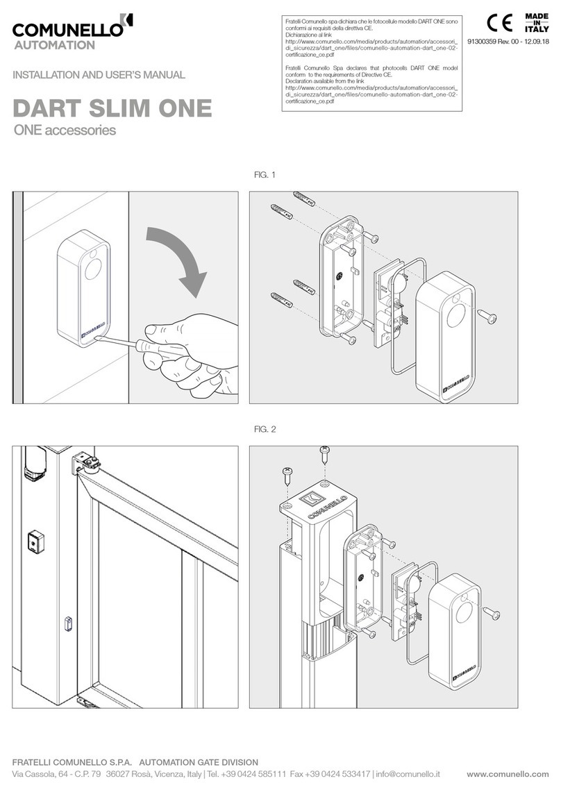
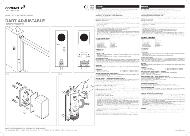
• Tras haber taladrado la caja en las cuatro esquinas, je la fotocélulas a la pared (FIG. 1).
• Utilice sistemas de jación aptos para el tipo de fotocélulas montadas (anclajes no incluidos).
• Antes de cerrar la fotocélula es necesario orientar la tarjeta del transmisor y del receptor con la nalidad de comunicarlos
entre sí. El receptor incorpora una luz testigo roja que se enciende cuando ambas fotocélulas están comunicadas.
• Para orientar la fotocélula, desenrosque el tornillo situado en la parte inferior y gire la tarjeta hasta que ambas
fotocélulas se comuniquen entre sí (FIG. 2).
CONEXIONES ELÉCTRICAS
DART BATTERY:
Fotocélulas codicadas de pared con el Transmisor con funcionamiento con batería, alcance hasta 16 metros.
La fotocélula con batería DART BATTERY resuelve los problemas asociados al tendido de los cables eléctricos
para la conexión del transmisor. La codicación de la señal transmitida, que se debe congurar en el momento de
la instalación, reduce la posibilidad de interferencia entre los dispositivos.
CARACTERÍSTICAS TÉCNICAS:
• Alcance máx.: 16 metri • Absorción RX: 25 mA Max.
• Alimentación TX: 1 x 1,5V pila Alcalina mod. AA • Capacidad contacto relé: 1A max a 30 VDC
• Alimentación RX: 12-24V AC-DC • Temperatura de servicio: -10 ÷ 55 °C
• Absorción TX: 0,30 mA Max.
TRANSMISOR:
Selección del Rango de Funcionamiento (SW1 Dip Switch n° 1):
La distancia máxima de funcionamiento de la fotocélula es de alrededor de 10 metros con la potencia normal (Dip
Switch n° 1 OFF “conguración de fábrica”) y de alrededor de 20 metros con la potencia máxima (Dip Switch n° 1 ON).
Selección de la Codicación de Funcionamiento “A” y “B” (SW1 Dip Switch n° 2):
La fotocélula incorpora dos canales de funcionamiento codicados “A” y “B”; de esta manera es posible instalar 2
pares del mismo modelo sin ninguna interferencia entre sí. La codicación “A” (Dip Switch n° 2 OFF “conguración
de fábrica”) y la codicación “B” (Dip Switch n° 2 ON) deben seleccionarse de manera adecuada al mismo tiempo,
en el momento de la instalación, tanto en la parte transmisora (IT 2241) como en la receptora (IR 2241).
Conexiones CN1: 1 – 12/24 Vac-dc 2 – 0V
FOTOCÉLULAS CODIFICADAS:
CARACTERÍSTICAS TÉCNICAS:
• Alcance máx.: 16 metri • Absorción RX: 25 mA Max.
• Alimentación TX: 1 x 1,5V pila Alcalina mod. AA • Capacidad contacto relé: 1A max a 30 VDC
• Alimentación RX: 12-24V AC-DC • Temperatura de servicio: -10 ÷ 55 °C
• Absorción TX: 0,30 mA Max.
DESCRIPCIÓN DEL TRANSMISOR (TX):
Alimentación y autonomía:
El transmisor está alimentado con una batería de 1,5 Voltios Alcalina. La duración media de una batería es de
alrededor de 18 meses con la potencia normal y de 12 meses con la potencia máxima. Dicha duración depende
de la calidad de las baterías utilizadas.
Selección del Rango de Funcionamiento (SW1 Dip Switch n° 1):
La distancia máxima de funcionamiento de la fotocélula es de alrededor de 8 metros con la potencia normal (Dip
Switch n° 1 OFF “conguración de fábrica”) y de alrededor de 16 metros con la potencia máxima (Dip Switch n° 1 ON).
Selección de la Codicación de Funcionamiento “A” y “B” (SW1 Dip Switch n° 2):
La fotocélula incorpora dos canales de funcionamiento codicados “A” y “B”; de esta manera es posible instalar 2
pares del mismo modelo sin ninguna interferencia entre sí. La codicación “A” (Dip Switch n° 2 OFF “conguración
de fábrica”) y la codicación “B” (Dip Switch n° 2 ON) deben seleccionarse de manera adecuada al mismo tiempo,
en el momento de la instalación, tanto en la parte transmisora como en la receptora.
Selección del tipo de dispositivo de seguridad:
Es posible conectar al transmisor un dispositivo de seguridad (por ejemplo una banda sensible que se debe montar
en el borde móvil de una puerta corredera): cuando se acciona el dispositivo, el transmisor interrumpe la transmisión.
Es posible seleccionar el tipo de dispositivo de seguridad a conectar mediante el jumper J1:
Pos. 1-2 = Dispositivo de seguridad con contacto 8k2 ohm.
Pos. 2-3 = Dispositivo de seguridad con contacto NC.
Conexiones: 1 – No utilizar 2 – No utilizar 3 - Dispositivo de seguridad 4 - Dispositivo de seguridad
ATENCIÓN: La batería alcalina 1.5 V (AA) debe sustituirse todos los años para asegurar un funcionamiento excelente.
RECEPTOR:
Alimentación: El receptor puede alimentarse con 12 o 24 Voltios tanto con corriente continua (respetar las
polaridades) como con corriente alterna.
Conexiones:
1 - Alimentación 0 Vca-Vcc 3 - Contacto fotocélula NA/NC (J1 selección)
2 - Alimentación 12-24 Vca-Vcc 4 - Contacto fotocélula NA/NC (J1 selección)
Selección Contacto Relé NA/NC (mediante Jumper J1):
Es posible seleccionar el tipo del contacto relé NA (Normalmente Abierto) o NC (Normalmente Cerrado).
J1 posición 1-2: Contacto relé NA.
J1 posición 2-3: Contacto relé NC (conguración de fábrica).
Selección Codicaciones de funcionamiento “A” y “B” (mediante Jumper J2):
La fotocélula incorpora dos canales codicados de funcionamiento “A” y “B”. Ponga mucha atención a que las codicaciones
estén seleccionadas de manera adecuada y de la misma manera, tanto en la fotocélula transmisora como en la receptora.
La codicación de funcionamiento “A” o “B” se realiza con el dip-switch J2:
J2 posición 1-2: Funcionamiento codicación B.
J2 posición 2-3: Funcionamiento codicación A (conguración de fábrica).
Control de la alineación entre Transmisor-Receptor:
En el receptor hay un LED 1 que indica que el par de fotocélulas está alineado. El LED 1 estará encendido con luz
ja cuando el rayo infrarrojo está alineado y se apagará cuando dicho rayo se interrumpe.
Comprobación de la calidad de la señal recibida:
En el receptor se encuentra el LED 2 que destella en función de la calidad de la señal recibida del transmisor
asociado. El número de destellos es proporcional a la intensidad de la señal recibida:
cuatro destellos = señal máxima,
un destello = señal insuciente.
IMPORTANTE PARA EL INSTALADOR
• En el caso de instalación múltiple de dispositivos, se aconseja crear franjas cruzadas (es decir transmisor A
y receptor B a la izquierda y transmisor B y receptor A a la derecha); si esto no fuera posible, mantenga una
distancia de al menos un metro (especialmente entre los receptores).
• Congure siempre la potencia mínima necesaria para cubrir la distancia de aplicación; esto permite aumentar
la duración de la batería y disminuir la posibilidad de interferencias con los dispositivos existentes.
• La fotocélula permite orientar el circuito en el interior de la caja; de esta manera es posible alinear el transmisor
con el receptor, evitando la recepción de señales de otros dispositivos.
• El dispositivo no debe ser utilizado por los niños o por personas con discapacidades psicofísicas, salvo que
estén controladas o sean instruidas sobre el funcionamiento y el modo de uso.
• No permita que los niños jueguen con el dispositivo y conserve los radiomandos lejos de su alcance.
• ATENCIÓN: conserve este manual de instrucciones y respete las prescripciones de seguridad importantes
que contiene. El incumplimiento de las prescripciones podría provocar daños y accidentes graves.
• Controle periódicamente el sistema para detectar cualquier señal de daño. No utilice el dispositivo si fuera
necesario realizar una reparación.
ELIMINACIÓN: Algunos componentes del producto pueden ser reciclados mientras que otros, como por ejemplo
los componentes electrónicos, deben ser eliminados en cumplimiento de las normativas vigentes en el lugar de
instalación. Algunos componentes podrían contener sustancias contaminantes y no deben abandonarse en el
medio ambiente.
HINWEISE
Dieses Installationshandbuch wendet sich ausschließlich an professionell kompetentes Personal.
Alle nicht ausdrücklich in dieser Anleitung erwähnten Vorgänge sind nicht erlaubt.
Es ist ganz besonders auf die folgenden Hinweise zu achten:
• Prüfen, dass die Netzspannung mit der Spannung an den Klemmen der Platine übereinstimmt.
• Den Strom abschalten, bevor die elektrischen Anschlüsse gefertigt werden.
PRODUKTBESCHREIBUNG UND BESTIMMUNGSZWECK
Kodierte Wand-Fotozellen, Senderbetrieb mit Akku, Reichweite bis 16 m.
Die Akku-Fotozelle DART BATTERY löst die Probleme der Stromkabeldurchführung für den Senderanschluss. Die
Kodierung der Signalübertragung erfolgt bei der Installation und reduziert die Möglichkeit von Interferenzen zwischen
den Vorrichtungen auf ein Minimum.
VORBEREITENDE ÜBERPRÜFUNGEN
• Prüfen, dass das in der Verpackung enthaltene Produkt einwandfrei und in gutem Zustand ist.
• Prüfen, dass die Positionierungsstelle der Fotozellen ihre korrekte Installation und Befestigung erlaubt.
INSTALLATION
• Die Fotozelle öffnen und die Kabel gemäß Schaltplan im Absatz „elektrische Anschlüsse“ an der
Klemmenleiste anschließen.
• An den vier Ecken der Dose Bohrungen fertigen und die Fotozellen an der Wand befestigen (ABB. 1).
• Für die Art der montierten Fotozellen geeignete Befestigungssysteme verwenden (Befestigungselemente
nicht inklusive).
• Vor dem Schließen der Fotozellen notfalls die Platinen des Senders und des Empfängers so richten, dass die
Kommunikation stattnden kann. Der Empfänger ist mit einer roten internen Kontrolllampe ausgestattet, die
einschaltet, wenn die zwei Fotozellen kommunizieren.
• Zum Orientieren der Fotozelle, die Schraube an der Unterseite losschrauben und die Platine drehen, bis die
Kommunikation zwischen den beiden Fotozellen hergestellt ist (ABB. 2).
ELEKTRISCHE ANSCHLÜSSE
DART BATTERY:
Kodierte Wand-Fotozellen, Senderbetrieb mit Akku, Reichweite bis 16 m.
Die Akku-Fotozelle DART BATTERY löst die Probleme der Stromkabeldurchführung für den Senderanschluss. Die
Kodierung der Signalübertragung erfolgt bei der Installation und reduziert die Möglichkeit von Interferenzen zwischen
den Vorrichtungen auf ein Minimum.
TECHNISCHE EIGENSCHAFTEN:
• Max. Reichweite: 16 m • Aufnahme RX: 25 mA Max.
• Speisung TX: 1x1,5V Alkali-Mangan Akku Mod. AA • Relaiskontaktleistung: 1A max. bei 30 VDC
• Speisung RX: 12-24V AC-DC • Betriebstemperatur: -10 ÷ 55 °C
• Aufnahme TX: 0,30 mA Max.
SENDER:
Wahl des Betriebsbereichs (SW1 Dip-Switch Nr. 1):
Die maximale Reichweite der Fotozelle beträgt ca. 10 Meter bei Normalleistung (Dip-Switch Nr. 1 Off „werkseitige
Konguration“) und ca. 20 Meter bei Höchstleistung (Dip-Switch Nr. 1 ON).
Wahl der Betriebskodierung „A“ und „B“ ( SW1 Dip-Switch Nr. 2 ):
Die Fotozelle besitzt zwei mit „A“ und „B“ kodierte Betriebskanäle; dadurch ist eine untereinander vollkommen
interferenzfreie Installation von 2 Paaren des gleichen Modells möglich. Die Kodierung „A“ (Dip-Switch Nr. 2 OFF
„werkseitige Konguration“) und „B“ (Dip-Switch Nr. 2 ON) sind bei der Installation sowohl am Sender (IT 2241) wie
auch am Empfänger (IR 2241) in gleicher Weise zu wählen.
Anschlüsse CN1: 1 – 12/24 Vac-dc 2 – 0V
KODIERTE FOTOZELLEN:
TECHNISCHE EIGENSCHAFTEN:
• Max. Reichweite: 16 m • Aufnahme RX: 25 mA Max.
• Speisung TX: 1x1,5V Alkali-Mangan Akku Mod. AA • Relaiskontaktleistung: 1A max. bei 30 VDC
• Speisung RX: 12-24V AC-DC • Betriebstemperatur: -10 ÷ 55 °
• Aufnahme TX: 0,30 mA Max.
BESCHREIBUNG DES SENDERS (TX):
Speisung und Autonomie:
Der Sender wird von einem 1,5 Volt Alkali-Mangan Akku gespeist. Durchschnittlich beträgt die Akku-Lebensdauer
ca. 18 Monate bei Normalleistung und ca. 12 Monate bei Höchstleistung.
Diese Lebensdauer ist von der Qualität der verwendeten Akkus abhängig.
Wahl des Betriebsbereichs (SW1 Dip-Switch Nr. 1):
Die maximale Reichweite der Akku-Fotozelle beträgt ca. 8 Meter bei Normalleistung (Dip-Switch Nr. 1 Off „werkseitige
Konguration“) und ca. 16 Meter bei Höchstleistung (Dip-Switch Nr. 1 ON).
Wahl der Betriebskodierung „A“ und „B“ (SW1 Dip-Switch Nr. 2):
Die Fotozelle besitzt zwei mit „A“ und „B“ kodierte Betriebskanäle; dadurch ist eine untereinander vollkommen
interferenzfreie Installation von 2 Paaren des gleichen Modells möglich. Die Kodierung „A“ (Dip-Switch Nr. 2 OFF
„werkseitige Konguration“) oder „B“ (Dip-Switch Nr. 2 ON) ist bei der Installation sowohl am Sender wie auch am
Empfänger in gleicher Weise zu wählen.
Wahl der Art der Sicherheitsvorrichtung:
Es besteht die Möglichkeit, am Sender eine Sicherheitsvorrichtung anzuschließen (z.B. eine an der beweglichen
Kante eines Schiebetors zu montierende Sicherheitsleiste): Wenn die Vorrichtung betätigt wird, unterbricht der
Sender die Übertragung.
Es besteht die Möglichkeit, die Art der mit dem Jumper J1 anzuschließenden Sicherheitsvorrichtung zu wählen:
Pos. 1-2 = Sicherheitsvorrichtung mit Kontakt 8k2 Ohm.
Pos. 2-3 = Sicherheitsvorrichtung mit NC-Kontakt.
Anschlüsse: 1 – Nicht verwenden 2 – Nicht verwenden 3 - Sicherheitsvorrichtung 4 - Sicherheitsvorrichtung
ACHTUNG: La batteria alcalina 1.5 V (AA) deve essere sostituita ogni anno per garantire il funzionamento ottimale
EMPFÄNGER:
Stromversorgung: Der Empfänger kann mit 12 oder 24 Volt versorgt werden, sowohl mit Gleichstrom (Polung
beachten) als auch mit Wechselstrom.
Anschlüsse:
1 - Stromversorgung 0 Vac-Vdc 3 – Kontakt Fotozelle NO/NC (J1 Wahl)
2 - Stromversorgung 12-24 Vac-Vdc 4 – Kontakt Fotozelle NO/NC (J1 Wahl)
Wahl Relaiskontakt NO/NC (mittels Jumper J 1):
Es besteht die Möglichkeit, die Art des Relaiskontakts NO (Schließer) oder NC (Öffner) zu wählen.
J1 Position 1- 2 : Relaiskontakt NO.
J1 Position 2-3 : Relaiskontakt NC (werkseitige Konguration).
Wahl der Betriebskodierung „A“ und „B“ (mittels Jumper J2):
Die Fotozelle besitzt zwei mit „A“ und „B“ kodierte Betriebskanäle. Es ist sorgfältig darauf zu achten, dass die
Kodierungen sowohl am Sender wie auch am Empfänger in gleicher Weise gewählt wurden.
Der Dip-Switch J2 dient für die Betriebskodierung „A“ oder „B“:
J2 Position 1- 2 : Betrieb Kodierung B.
J2 Position 2-3 : Betrieb Kodierung A (werkseitige Konguration).
Prüfung der Ausrichtung Sender-Empfänger:
Auf dem Empfänger bendet sich die Led 1, die auf die Ausrichtung des Fotozellenpaars hinweist. Die Led 1 ist
mit Festlicht eingeschaltet, wenn der Infrarotstrahl ausgerichtet ist und schaltet aus, wenn er unterbrochen wird.
Prüfung der Qualität des empfangenen Signals:
Auf dem Empfänger bendet sich die Led 2, die in Funktion der Qualität des vom zugehörigen Sender eingegangenen
Signals blinkt. Die Blinkzahl ist proportional zur Intensität des empfangenen Signals:
viermaliges Blinken=starkes Signal,
einmaliges Blinken=unzureichendes Signal.
WICHTIGE HINWEISE FÜR DEN INSTALLATEUR
• Im Falle einer mehrfachen Installation von Vorrichtungen wird empfohlen, gekreuzte Bündel zu bilden (d.h.
Sender A und Empfänger B links und Sender B und Empfänger A rechts); ist dies nicht möglich, dann ist in
jedem Fall ein Abstand von mindestens einem Meter einzuhalten (vor allem zwischen den Empfängern).
• Immer die zur Deckung des Nutzungsabstandes notwendige Mindestleistung einstellen: Dadurch können die Akku-
Dauer erhöht und die möglichen Interferenzen mit den anderen vorhandenen Vorrichtungen reduziert werden.
• Die Fotozelle erlaubt die Orientierung des Schaltkreises im Innern der Dose: Dadurch können Sender und
Empfänger ausgerichtet und eventuell der Empfang seitens anderer Vorrichtungen vermieden werden.
• Die Vorrichtung darf nicht von Kindern oder Personen mit unzureichenden psychisch-physischen Fähigkeiten
verwendet werden, es sei denn, sie werden überwacht oder über den Betrieb und die Benutzungsmethoden belehrt.
• Kindern darf nicht erlaubt werden, mit der Vorrichtung zu spielen; außerdem sind die Funksteuerungen vor
Kindern fern zu halten.
• ACHTUNG: Dieses Anleitungshandbuch ist aufzubewahren und die darin enthaltenen wichtigen Sicherheitsvorschriften
zu beachten. Das Nichtbeachten der Vorschriften könnte Schäden und schwere Unfälle verursachen.
• Die Anlage häug untersuchen, um eventuelle Zeichen von Beschädigungen festzustellen. Die Vorrichtung nicht
verwenden, wenn sie reparaturbedürftig ist.
ENTSORGUNG: Einige Bestandteile des Produkts können rezykliert werden, während andere wie z.B. die
elektronischen Bestandteile nach den im Installationsgebiet geltenden Vorschriften entsorgt werden müssen.
Einige Bestandteile könnten Schadstoffe enthalten und dürfen nicht in der Umwelt zerstreut werden.
ПРЕДУПРЕЖДЕНИЯ
Настоящее руководство по монтажу предназначено исключительно для профессионального
компетентного персонала. Все то, что не предусмотрено в настоящем руководстве, не разрешено.
Особое внимание следует обращать на перечисленные ниже предупреждения:
• Проверьте, что напряжение питания одинаковое и соответствует напряжению на клеммах платы.
• Отключите напряжение перед выполнением электрических соединений.
ОПИСАНИЕ ИЗДЕЛИЯ И ПРЕДУСМОТРЕННОЕ ИСПОЛЬЗОВАНИЕ
Кодированные настенные фотоэлементы, работающие от передатчика с батарейкой, дальность
действия до 16 м. Фотоэлемент с батарейками DART BATTERY решает проблемы, связанные с
прокладкой электрических кабелей для соединения передатчика. Кодировка передаваемого сигнала,
задаваемая в момент монтажа, минимизирует возможность помех между устройствами.
ПРЕДВАРИТЕЛЬНЫЕ ПРОВЕРКИ
• Необходимо проверить целостность и хорошее состояние изделия внутри упаковки.
• Проверьте, что место установки фотоэлементов позволяет правильный монтаж и крепление
фотоэлементов.
МОНТАЖ
• Откройте фотоэлемент и соедините кабели с клеммником, в соответствии со схемой в параграфе
“ электрические соединения “.
• После того, как вы просверлили коробку в четырех углах, прикрепите фотоэлементы к стене (РИС. 1).
• Используйте системы крепления, подходящие к типу стойки (крепления не включены).
• Перед тем, как закрывать фотоэлемент, ориентируйте при необходимости плату передатчика и
приемника таким образом, чтобы они сообщались друг с другом. Приемник оснащен внутренним
красным индикатором, который загорается, когда два фотоэлемента ведут сообщение.
• Для ориентации фотоэлемента нужно отвинтить винт в нижней части и поворачивать плату до тех
пор, пока два фотоэлемента не вступят между собой в сообщение (РИС. 2).
ЭЛЕКТРИЧЕСКИЕ СОЕДИНЕНИЯ
DART BATTERY:
Кодированные настенные фотоэлементы, работающие от передатчика на батарейке, дальность
действия до 16 м. Фотоэлемент на батарейках DART BATTERY решает проблемы, связанные с
прокладкой электрических кабелей для соединения передатчика. Кодировка передаваемого сигнала,
задаваемая в момент монтажа, минимизирует возможность помех между устройствами.
ТЕХНИЧЕСКИЕ ХАРАКТЕРИСТИКИ:
• Макс. дальность действия: 16 метров • Потребление RX: 25 мА макс.
• Питание TX: 1x1,5 В щелочная батарейка мод. AA • Сила контактов реле: 1 A макс. при 30 В
• Питание RX: 12-24 В AC-DC постоянного токаVDC
• Потребление TX: 0,30 мА макс • Рабочая температура: -10 ÷ 55 °C
ПЕРЕДАТЧИК:
Выбор диапазона работы (SW1 Dip Switch № 1):
Максимальная дистанция работы фотоэлемента составляет около 10 метров при нормальной
мощности (Dip Switch № 1 ВЫКЛ. “заводская конфигурация”) и около 20 метров при максимальной
мощности (Dip Switch № 1 ВКЛ.).
Выбор кодировки работы “A” и “B“ (SW1 Dip Switch № 2):
Фотоэлемент располагает двумя закодированными каналами “A” и “B” для работы, таким образом
можно установить 2 пары одной модели, без каких-либо помех между ними. Кодировка “A” (Dip Switch
№ 2 ВЫКЛ. “заводская конфигурация”) и кодировка “B” (Dip Switch № 2 ВКЛ.), должны быть настроены
одинаково, в момент монтажа, как в части передатчика (IT 2241), так и в части приемника (IR 2241).
Соединения CN1: 1 – 12/24 Vac-dc 2 – 0V
КОДИРОВАННЫЕ ФОТОЭЛЕМЕНТЫ
ТЕХНИЧЕСКИЕ ХАРАКТЕРИСТИКИ:
• Макс. дальность действия: 16 метров • Потребление RX: 25 мА макс.
• Питание TX: 1x1,5 В щелочная батарейка мод. AA • Сила контактов реле: 1 A макс. при 30 В
• Питание RX: 12-24 В AC-DC постоянного токаVDC
• Потребление TX: 0,30 мА макс • Рабочая температура: -10 ÷ 55 °C
Описание передатчика (TX):
Питание и автономная работа:
Передатчик получает питание от щелочной батарейки 1,5 Вольт. Средняя продолжительность
работы батарейки составляет около 18 месяцев при нормальной мощности и около 12 месяцев при
максимальной мощности. Эта продолжительность зависит от качества используемых батареек.
Выбор диапазона работы (SW1 Dip Switch № 1):
Максимальная рабочая дистанция фотоэлемента составляет около 8 метров при нормальной
мощности (Dip Switch № 1 ВЫКЛ. “заводская конфигурация”) и около 16 метров при максимальной
мощности (Dip Switch № 1 ВКЛ.).
Выбор кодировки работы “A” и “B“ (SW1 Dip Switch № 2):
Фотоэлемент располагает двумя закодированными каналами “A” и “B” для работы, таким образом
можно установить 2 пары одной модели, без каких-либо помех между ними. Кодировка “A” (Dip Switch
№ 2 ВЫКЛ. “заводская конфигурация”) и кодировка “B” (Dip Switch № 2 ВКЛ.), должны быть настроены
одинаково, в момент монтажа, как в части передатчика, так и в части приемника.
Выбор типа устройства безопасности:
Можно соединить передатчик с устройством безопасности (например, чувствительная кромка для
монтажа на подвижный край передвижных ворот): когда устройство начинает работать, передатчик
прерывает передачу.
Можно выбрать тип устройства безопасности для соединения при помощи перемычки J1:
Поз. 1-2 = Устройство безопасности с контактом 8k2 Ом.
Поз. 2-3 = Устройство безопасности с контактом NC.
Соединения: 1 – не использовать 2 – не использовать 3 - Устройство безопасности 4 - Устройство безопасности
ВНИМАНИЕ: Щелочная батарейка 1.5 В ( AA ) должна заменяться ежегодно для того, чтобы гарантировать
оптимальную работу
ПРИЕМНИК:
Питание: Приемник может получать питание 12 или 24 Вольт как постоянного тока, так и (соблюдать
полярность) переменного тока.
Соединения:
1 - Питание 0 Vac-Vdc 3 - Контакт фотоэлемента NA/NC (выбор J1)
2 - Питание 12-24 Vac-Vdc 4 - Контакт фотоэлемента NA/NC (выбор J1)
Выбор контакта реле NA/NC (при помощи перемычки J 1):
Можно выбрать тип контакта реле NA (нормально разомкнутый) или NC (нормально замкнутый).
J1 положение 1- 2 : Контакт реле NA.
J1 положение 2- 3 : Контакт реле NC (заводская конфигурация).
Выбор кодировки “A” и “B“ для работы (при помощи перемычки J2):
Фотоэлемент располагает двумя закодированными каналами “A” и “B” для работы. Соблюдайте
осторожность, чтобы все кодировки были выбраны одинаково, как на передатчике, так и на приемнике.
Кодировка работы “A“ или ”B“ выполняется при помощи выключателя di-switch J2:
J2 положение 1- 2 : Работа кодировки B.
J2 положение 2- 3 : Работа кодировки A (заводская конфигурация ).
Проверка выравнивания передатчика-приемника:
На приемнике имеется Светодиод 1, указывающий на выравнивание пары фотоэлементов.
Светодиод 1 будет гореть постоянным светом, когда инфракрасный луч выровнен и погаснет при
прерывании инфракрасного луча.
Проверка качества полученного сигнала:
На приемнике имеется Светодиод 2, мигающий в зависимости от качества сигнала, получаемого со
стороны подсоединенного к нему передатчика. Количество миганий пропорционально интенсивности
полученного сигнала:
четыре мигания=максимальный сигнал,
одно мигание= недостаточный сигнал.
ВАЖНОЕ ПРИМЕЧАНИЕ ДЛЯ МОНТАЖНИКА:
• В случае множественной установки устройств, рекомендуется создавать пересекающиеся пучки (то
есть передатчик A и приемник B слева и передатчик B и приемник A справа). В тех случаях, когда это
невозможно, нужно соблюдать минимальное расстояние (особенно между приемниками) в один метр.
• Всегда задавайте минимальную необходимую мощность для покрытия рабочего расстояния: это позволяет
увеличить срок службы батарейки и уменьшить возможность помех от других внешних устройств.
• Фотоэлемент позволяет ориентировать контур внутри коробки: таким образом можно выровнять
передатчик с приемником, избегая приема со стороны других устройств
• Устройство не должно использоваться детьми или людьми с ограниченными психическими и физическими
способностями, за исключением случаев, когда они находятся под руководством или обучены работе и
способам использования.
• Не разрешайте детям играть с устройством и храните в недоступном для них месте пульты
радиоуправления.
• ВНИМАНИЕ: храните эти инструкции и выполняйте предписания по безопасности, приведенные в этом
руководстве. Несоблюдение инструкций может привести к причинению ущерба и серьезным несчастным случаям.
• Регулярно проверяйте установку для выявления признаков повреждений. Не используйте устройство,
если его нужно отремонтировать.
ВЫВОЗ В ОТХОДЫ: Некоторые компоненты изделия могут повторно утилизироваться, в то время
как другие части, такие, как, например, электронные компоненты, должны вывозиться в отходы в
соответствии с действующими в зоне установки нормативами.
Некоторые компоненты могут содержать загрязняющие вещества и не должны выбрасываться в
окружающей среде.
AVERTISSEMENT
Ce manuel d’installation s’adresse exclusivement à un personnel compétent.
Toutes les opérations non expressément prévues dans ces instructions sont interdites
Il est en particulier indispensable de respecter les consignes suivantes:
• Vérier que la tension d’alimentation est identique à celle des bornes de la carte.
• Toutes les connexions électriques doivent être effectuées en l’absence de tension
DESCRIPTION DU PRODUIT ET APPLICATION
Photocellules codées murales avec fonctionnement émetteur à batterie, portée max. 16 m.
La photocellule à batterie DART BATTERY élimine tous les problèmes de passage des câbles pour le branchement
de l’émetteur. Le codage du signal transmis, qui doit être déni lors de l’installation, réduit les risques d’interférences
entre les dispositifs.
CONTRÔLES PRÉLIMINAIRES
• Vérifier que le contenu de l’emballage est en parfait état.
• Vérifier que les photocellules sont fixées sur une surface solide et adaptée à ces dernières.
INSTALLATION
• Ouvrir la photocellule et brancher les câbles au bornier selon le schéma du paragraphe «Branchements électriques».
• Après avoir percé le boîtier aux quatre angles, xer les photocellules au mur (FIG. 1).
• Utiliser des systèmes de xation adaptés au montant (non inclus).
• Avant de fermer la photocellule, orienter si nécessaire la carte de l’émetteur et du récepteur de façon à les placer en
communication. Le récepteur comprend un voyant interne rouge qui s’allume si les deux photocellules communiquent.
• Pour orienter la photocellule, desserrer la vis de sa partie inférieure et faire pivoter la carte jusqu’à établir une
communication entre les deux photocellules (FIG. 2).
BRANCHEMENTS ÉLECTRIQUES
DART BATTERY:
Photocellules codées murales avec fonctionnement émetteur à batterie, portée max. 16 m.
La photocellule à batterie DART BATTERY élimine tous les problèmes de passage des câbles pour le branchement
de l’émetteur. Le codage du signal transmis, qui doit être déni lors de l’installation, réduit les risques d’interférences
entre les dispositifs.
CARACTÉRISTIQUES TECHNIQUES:
• Portée max.: 16 metri • Absorption RX: 25 mA Max.
• Alimentation TX: 1 x 1,5V pile alcaline mod. AA • Portée contact relais: 1A max à 30 VDC
• Alimentation RX: 12-24V AC-DC • Température de service: -10 ÷ 55 °C
• Absorption TX: 0,30 mA Max.
ÉMETTEUR:
Sélection plage de fonctionnement (SW1 dip-switch n°1):
La photocellule offre une distance de fonctionnement max. d’environ 8 mètres à la puissance normale (dip-switch
n°1 OFF «conguration d’usine»). et d’environ 16 mètres à la puissance maximale (dip-switch n°1 ON).
Sélection codage A et B de fonctionnement (SW1 dip-switch n°2):
La photocellule dispose de deux canaux codés A et B de fonctionnement, et il est ainsi possible d’installer 2 paires
du même modèle sans aucune interférence entre ces dernières. Le codage A (dip-switch n°2 OFF «conguration
d’usine») et le codage B (dip-switch n°2 ON) doivent être sélectionnés de façon identique lors de l’installation, du
côté émetteur (IT 2241) comme du côté récepteur (IR 2241).
Branchements CN1: 1 – 12/24 Vac-dc 2 – 0V
PHOTOCELLULESCODÉES:
CARACTÉRISTIQUES TECHNIQUES:
• Portée max.: 16 metri • Absorption RX: 25 mA Max.
• Alimentation TX: 1 x 1,5V pile alcaline mod. AA • Portée contact relais: 1A max à 30 VDC
• Alimentation RX: 12-24V AC-DC • Température de service: -10 ÷ 55 °C
• Absorption TX: 0,30 mA Max.
DESCRIPTION DE L’ÉMETTEUR (TX):
Alimentation et autonomie:
L’émetteur est alimenté par une batterie d’1,5 V alcaline. La durée moyenne d’une batterie est d’environ 18 mois
à la puissance normale et d’environ 12 mois à la puissance maximum. Cette durée est fonction de la qualité des
batteries utilisées.
Sélection plage de fonctionnement (SW1 dip-switch n° 1):
La photocellule à batterie offre une distance de fonctionnement max. d’environ 8 mètres à la puissance normale
(dip-switch n°1 OFF «conguration d’usine»), et d’environ 16 mètres à la puissance maximum (dip-switch n°1 ON).
Sélection codage A et B de fonctionnement (SW1 dip-switch n° 2):
La photocellule dispose de deux canaux codés A et B de fonctionnement, et il est ainsi possible d’installer 2 paires
du même modèle sans aucune interférence entre ces dernières. Le codage A (dip-switch n°2 OFF «conguration
d’usine») et le codage B (dip-switch n° 2 ON) doivent être sélectionnés de façon identique lors de l’installation, du
côté émetteur comme du côté récepteur.
Sélection du type de dispositif de sécurité:
Il est possible de connecter à l’émetteur un dispositif de sécurité (par exemple barre palpeuse montée sur le bord
mobile d’un portail coulissant): l’actionnement du dispositif entraîne l’interruption de la transmission de l’émetteur.
Il est possible de sélectionner le type de dispositif de sécurité à connecter via le cavalier J1:
Pos. 1-2 = Dispositif de sécurité à contact 8k2 ohms.
Pos. 2-3 = Dispositif de sécurité à contact NF.
Branchements: 1 – Ne pas utiliser 2 – Ne pas utiliser 3 - Dispositif de sécurité 4 - Dispositif de sécurité
ATTENTION: La batterie alcaline 1.5 V (AA) doit être remplacée chaque année en vue d’un fonctionnement optimal.
RÉCEPTEUR:
Alimentation: Le récepteur peut être alimenté à 12 ou 24 V, et en courant continu (respecter les polarités) ou alternatif.
Branchements:
1 - Alimentation 0 Vca-Vcc 3 - Contact photocellule NO/NF (J1 sélection)
2 - Alimentation 12-24 Vca-Vcc 4 - Contact photocellule NO/NF (J1 sélection)
Sélection contact relais NO/NF (via cavalier J 1):
Le contact relais peut être sélectionné comme NO (normalement ouvert) ou NF (normalement fermé).
J1 position 1- 2 : Contact relais NO.
J1 position 2-3 : Contact relais NF (conguration d’usine).
Sélection codage A et B de fonctionnement (via cavalier J2):
La photocellule dispose de deux canaux codés A et B de fonctionnement. Les deux codages doivent être
sélectionnés de façon identique lors de l’installation, du côté émetteur comme du côté récepteur.
Le codage de fonctionnement A ou B s’effectue via le dip-switch J2:
J2 position 1- 2 : Fonctionnement codage B.
J2 position 2-3 : Fonctionnement codage A (conguration d’usine).
Vérication alignement émetteur-récepteur:
La Led 1 prévue sur le récepteur indique si la paire de photocellules est alignée.
La Led 1 est allumée xe si le rayon infrarouge est aligné, et elle s’éteint si le rayon infrarouge est interrompu.
Vérication de la qualité du signal en réception:
La Led 2 prévue sur le récepteur clignote en fonction de la qualité du signal transmis par l’émetteur associé. Le
nombre de clignotements est proportionnel à l’intensité du signal reçu:
quatre clignotements = signal optimal,
un clignotement = signal insufsant.
NOTE IMPORTANTE POUR L’INSTALLATEUR
• En cas d’installation de plusieurs dispositifs, il est conseillé de prévoir des faisceaux croisés (émetteur A et
récepteur B à gauche, émetteur B et récepteur A à droite); en cas d’impossibilité, ménager une distance min.
d’1 m (en particulier entre les récepteurs).
• Toujours congurer la distance minimum nécessaire à couvrir la distance d’application, ce qui permet de
prolonger la durée de vie de la batterie et réduit les risques d’interférence avec les autres dispositifs installés.
• La photocellule permet d’orienter le circuit à l’intérieur du boîtier, et donc d’aligner émetteur et récepteur en
évitant tout risque de réception par d’autres dispositifs.
• Le dispositif ne doit pas être utilisé par les enfants ou par des personnes disposant de capacités psycho-
physiques réduites, sauf si ces dernières l’utilisent sous surveillance ou ont reçu des instructions concernant
son fonctionnement et ses modes d’utilisation.
• Ne pas laisser les enfants jouer avec le dispositif et ne pas laisser les radiocommandes à leur portée.
• ATTENTION: conserver ce manuel d’instructions et respecter les prescriptions importantes concernant la
sécurité contenues. - Le non-respect de ces prescriptions peut entraîner des dommages et accidents graves.
• Examiner fréquemment l’installation à la recherche de tout signe d’endommagement. - Ne pas utiliser le
dispositif si une intervention de réparation est nécessaire.
ÉLIMINATION: Certains composants du produit peuvent être recyclés, tandis que d’autres (ex. composants
électroniques) doivent être mis au rebut selon les normes en vigueur au lieu d’installation.
Certains composants peuvent contenir des substances polluantes et ne doivent pas être jetés dans l’environnement.
