DEUTSCH ESPAÑOL РУССКИЙ
FRANÇAIS
ADVERTENCIAS
Elpresentemanualdeinstalaciónestádirigidoexclusivamentealpersonalprofesionalmentecapacitado.
Todoaquelloquenoestáprevistoexpresamenteenestasinstruccionesnoestápermitido.
En particular, es importante poner atención a las siguientes advertencias:
• Compruebequelatensióndealimentaciónseaigualaaquellaquehayenlasbornasdelatarjeta.
• Cortelatensiónantesderealizarlasconexioneseléctricas.
DESCRIPCIÓN DEL PRODUCTO Y USO PREVISTO
LasfotocélulasDARTADJUSTABLEsonfotocélulasdeparedconunalcancedehasta20metros.La
codificación de la señal transmitida, que se debe configurar en el momento de la instalación, permite la
instalaciónde2paresdefotocélulasdelmismomodelosinningunainterferenciaentresí.
CONTROLES PRELIMINARES
• Compruebequeelproductoembaladoestéíntegroyenbuenascondiciones.
• Compruebequeellugardeinstalacióndelasfotocélulaspermitaunmontajeyunafijacióncorrectadelas
mismasfotocélulas.
INSTALACIÓN
• Abra las fotocélulas y conecte los cables a la bornera según el diagrama del apartado
“conexioneseléctricas”.
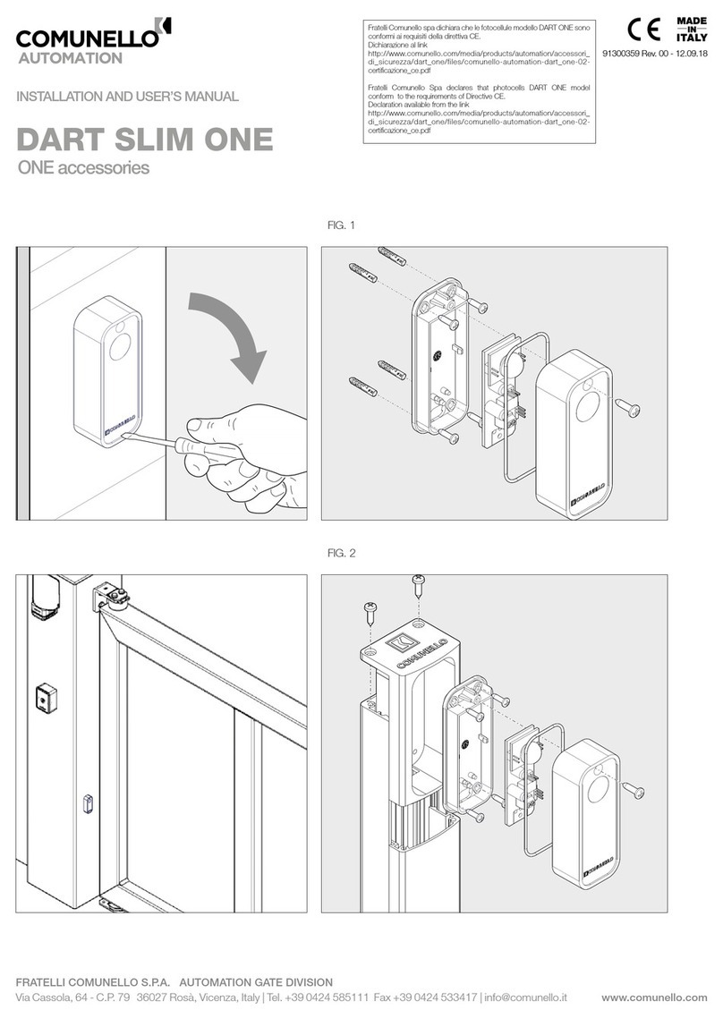
• Trashabertaladradolacajaenlascuatroesquinas,jelafotocélulasalapared(FIG.1).
• Utilicesistemasdejaciónaptosparaeltipodefotocélulasmontadas(anclajesnoincluidos).
• Asegúresedequeeltransmisoryelreceptoresténconectados.
• Antesdecerrarlafotocélulaesnecesarioorientarlatarjetadeltransmisorydelreceptorconlanalidad
de comunicarlos entre sí. El receptor incorpora una luz testigo roja que se enciende cuando ambas
fotocélulasestáncomunicadas.
• Paraorientarlafotocélula,desenrosqueeltornillosituadoenlaparteinferiorygirelatarjetahastaque
eltransmisoryelreceptorsecomuniquen entresí.Alconcluirlaalineación,el LED1delreceptorse
enciende(FIG.2).
• Enrosqueeltornilloycierrelacubiertadelafotocélula.
CONEXIONES ELÉCTRICAS
CARACTERÍSTICAS TÉCNICAS:
• Alcancemáx.: 20metros
• AlimentaciónTX: 12-24VCA-CC
• AlimentaciónRX: 12-24VCA-CC
• AbsorciónTX: 10mAmáx.
• AbsorciónRX: 25mAmáx.
• Capacidadcontactorelé: 1Amáx.a30Vcc
• Temperaturadeservicio: -10÷55°C
Conexiones CN1:
1–12/24Vac-dc
2–0V
TRANSMISOR:
• Elproductosesuministraconunadistanciadefuncionamientomáximadealrededorde10metroscon
unapotencianormal(DipSwitchn°1OFF).
• Desplazandoeldip-switchhacialaposiciónONseobtieneunadistanciamáximade20metros.
Sincronización de las fotocélulas:
Lafotocélula incorpora doscanales codicados defuncionamiento “A” y “B”. De esta maneraes posible
instalar2paresdelmismomodelosininterferenciaentresí.Elproductosesuministraconlacodicación“A”
(DipSwitchn°2enlaposiciónOFF).Paraobtenerlacodicación“B”,desplaceeldip-switchhacialaposición
“ON”.Ambascodicacionesdebenseleccionarsedemaneraoportunaenelmismomodo,enelmomentode
la instalación, tanto en la parte transmisora como en la parte receptora.
RECEPTOR:
Alimentación: Elreceptorpuedealimentarsecon12o24Voltiostantoconcorrientecontinua(respetarlas
polaridades)comoconcorrientealterna.
Conexiones:
1-Alimentación0Vca-Vcc 3-ContactofotocélulaNA/NC(J1selección)
2-Alimentación12-24Vca-Vcc 4-ContactofotocélulaNA/NC(J1selección)
Selección Contacto Relé NA/NC (mediante Jumper J1):
EsposibleseleccionareltipodelcontactoreléNA(NormalmenteAbierto)oNC(NormalmenteCerrado).
J1posición1-2:ContactoreléNA.
J1posición2-3:ContactoreléNC(conguracióndefábrica).
Selección Codicaciones de funcionamiento “A” y “B” (mediante Jumper J2):
Lafotocélulaincorporadoscanalescodicadosdefuncionamiento“A”y“B”.Pongamuchaatenciónaque
lascodicacionesesténseleccionadasdemaneraadecuadaydelamismamanera,tantoenlafotocélula
transmisora como en la receptora.
Lacodicacióndefuncionamiento“A”o“B”serealizaconeldip-switchJ2:
J2posición1-2:FuncionamientocodicaciónB.
J2posición2-3:FuncionamientocodicaciónA(conguracióndefábrica).
Control de la alineación entre Transmisor-Receptor:
EneltransmisorhayunLED1queindicaqueelpardefotocélulasestáalineado.ElLED1estaráencendido
conluzjacuandoelrayoinfrarrojoestáalineadoyseapagarácuandodichorayoseinterrumpe.
Comprobación de la calidad de la señal recibida:
EnelreceptorseencuentraelLED2quedestellaenfuncióndelacalidaddelaseñalrecibidadeltransmisor
asociado.Elnúmerodedestellosesproporcionalalaintensidaddelaseñalrecibida:
cuatrodestellos=señalmáxima,
undestello=señalinsuciente.
IMPORTANTE PARA EL INSTALADOR
• Enelcasodeinstalaciónmúltiplededispositivos,seaconsejacrearfranjascruzadas(esdecirtransmisor
AyreceptorBalaizquierdaytransmisorByreceptorAaladerecha);siestonofueraposible,mantenga
unadistanciadealmenosunmetro(especialmenteentrelosreceptores).
• Conguresiemprelapotenciamínimanecesariaparacubrirladistanciadeaplicación;estopermiteaumentar
laduracióndelabateríaydisminuirlaposibilidaddeinterferenciasconlosdispositivosexistentes.
• Eldispositivonodebeserutilizadoporlosniñosoporpersonascondiscapacidadespsicofísicas,salvo
queesténcontroladasoseaninstruidassobreelfuncionamientoyelmododeuso.
• Nopermitaquelosniñosjueguenconeldispositivoyconservelosradiomandoslejosdesualcance.
• ATENCIÓN:conserveestemanualdeinstruccionesyrespetelasprescripcionesdeseguridadimportantes
quecontiene.Elincumplimientodelasprescripcionespodríaprovocardañosyaccidentesgraves.
• Controleperiódicamenteelsistemaparadetectarcualquierseñaldedaño.Noutiliceeldispositivosifuera
necesario realizar una reparación.
ELIMINACIÓN
Algunos componentes del producto pueden ser reciclados mientras que otros, como por ejemplo los
componentes electrónicos, deben ser eliminados en cumplimiento de las normativas vigentes en el lugar de
instalación.Algunoscomponentespodríancontenersustanciascontaminantesynodebenabandonarseen
el medio ambiente.
HINWEISE
DiesesInstallationshandbuchwendetsichausschließlichanprofessionellkompetentesPersonal.
AllenichtausdrücklichindieserAnleitungerwähntenVorgängesindnichterlaubt.
EsistganzbesondersaufdiefolgendenHinweisezuachten:
• Prüfen,dassdieNetzspannungmitderSpannungandenKlemmenderPlatineübereinstimmt.
• DenStromabschalten,bevordieelektrischenAnschlüssegefertigtwerden.
PRODUKTBESCHREIBUNG UND BESTIMMUNGSZWECK
DieFotozellenDARTADJUSTABLEmiteinerReichweitebis20msindfürdieWandbefestigungkonzipiert.
DieKodierungderSignalübertragungerfolgtbeiderInstallationundermöglichteineuntereinandervollkommen
interferenzfreieInstallationvon2PaarendesgleichenModells.
VORBEREITENDE ÜBERPRÜFUNGEN
• Prüfen,dassdasinderVerpackungenthalteneProdukteinwandfreiundingutemZustandist.
• Prüfen,dassdiePositionierungsstellederFotozellenihrekorrekteInstallationundBefestigungerlaubt.
INSTALLATION
• Die Fotozellen öffnen und die Kabel gemäß Schaltplan im Absatz „elektrische Anschlüsse“ an der
Klemmenleisteanschließen.
• AndenvierEckenderDoseBohrungenfertigenunddieFotozellenanderWandbefestigen(ABB.1).
• FürdieArtdermontiertenFotozellengeeigneteBefestigungssystemeverwenden(Befestigungselemente
nichtinklusive).
• Zuerstsicherstellen,dassSenderundEmpfängerangeschlossensind.
• VordemSchließenderFotozellennotfallsdiePlatinendesSendersunddesEmpfängerssorichten,dass
dieKommunikationstattndenkann.DerEmpfängeristmiteinerroteninternenKontrolllampeausgestattet,
dieeinschaltet,wenndiezweiFotozellenkommunizieren.
• UmdieFotozellenorientierungzuregeln,dieSchraubeanderUnterseitelosschraubenunddiePlatine
drehen,bisdieKommunikationzwischenSenderundEmpfängerhergestelltist.Sobaldsieausgerichtet
sind,schaltetdieLed1desEmpfängersein(ABB.2).
• DieSchraubewiedereinschraubenunddenFotozellendeckelschließen.
ELEKTRISCHE ANSCHLÜSSE
TECHNISCHE EIGENSCHAFTEN:
• Max.Reichweite: 20m
• SpeisungTX: 12-24VAC-DC
• SpeisungRX: 12-24VAC-DC
• AufnahmeTX: Max.10mA
• AufnahmeRX: Max.25mA
• Relaiskontaktleistung: 1Amax.bei30Vdc
• Betriebstemperatur: -10÷55°C
Anschlüsse CN1:
1–12/24Vac-dc
2–0V
SENDER:
• DasProduktwirdmiteinermax.Reichweitevonca.10mbeiNormalleistunggeliefert(Dip-SwitchNr.1OFF).
• WennderDip-SwitchaufONgeschaltetwird,wirdeinemax.Reichweitevon20merzielt.
Synchronisierung der Fotozellen:
DieFotozelle besitzt zwei mit „A“und „B“ kodierte Betriebskanäle. Dadurch können ganz ohne Interferenzen
untereinander2PaarevomgleichenModellinstalliertwerden.DasProduktwirdmitderKodierung„A“geliefert
(Dip-SwitchNr.2aufOFF“).UmaufKodierung„B“zuschalten,istderDip-Switchauf„ON“zurücken.
BeideKodierungensindbeiderInstallationsowohlsender-wieauchempfängerseitigingleicherWeisezuwählen.
EMPFÄNGER:
Stromversorgung: DerEmpfängerkannmit12oder24Voltversorgtwerden,sowohlmitGleichstrom(Polung
beachten)alsauchmitWechselstrom.
Anschlüsse:
1-Stromversorgung0Vac-Vdc 3–KontaktFotozelleNO/NC(J1Wahl)
2-Stromversorgung12-24Vac-Vdc 4–KontaktFotozelleNO/NC(J1Wahl)
Wahl Relaiskontakt NO/NC (mittels Jumper J 1):
EsbestehtdieMöglichkeit,dieArtdesRelaiskontaktsNO(Schließer)oderNC(Öffner)zuwählen.
J1Position1-2:RelaiskontaktNO.
J1Position2-3:RelaiskontaktNC(werkseitigeKonguration).
Wahl der Betriebskodierung „A“ und „B“ (mittels Jumper J2):
DieFotozellebesitztzweimit„A“und„B“kodierteBetriebskanäle.Esistsorgfältigdaraufzuachten,dassdie
KodierungensowohlamSenderwieauchamEmpfängeringleicherWeisegewähltwurden.
DerDip-SwitchJ2dientfürdieBetriebskodierung„A“oder„B“:
J2Position1-2:BetriebKodierungB.
J2Position2-3:BetriebKodierungA(werkseitigeKonguration).
Prüfung der Ausrichtung Sender-Empfänger:
AufdemEmpfängerbendetsichdieLed1,dieaufdieAusrichtungdesFotozellenpaarshinweist.
DieLed1istmitFestlichteingeschaltet,wenn derInfrarotstrahlausgerichtetistundschaltetaus,wenn er
unterbrochenwird.
Prüfung der Qualität des empfangenen Signals:
Auf dem Empfänger bendet sich die Led 2, die in Funktion der Qualität des vom zugehörigen Sender
eingegangenenSignalsblinkt.DieBlinkzahlistproportionalzurIntensitätdesempfangenenSignals:
viermaligesBlinken=starkesSignal,
einmaligesBlinken=unzureichendesSignal.
WICHTIGE HINWEISE FÜR DEN INSTALLATEUR
• ImFalleeinermehrfachenInstallationvonVorrichtungenwirdempfohlen,gekreuzteBündelzubilden(d.h.
SenderAundEmpfängerBlinksundSenderBundEmpfängerArechts);istdiesnichtmöglich,dannist
injedemFalleinAbstandvonmindestenseinemMetereinzuhalten(vorallemzwischendenEmpfängern).
• ImmerdiezurDeckungdesNutzungsabstandesnotwendigeMindestleistungeinstellen:Dadurchkönnen
die Akku-Dauer erhöht und die möglichen Interferenzen mit den anderen vorhandenen Vorrichtungen
reduziertwerden.
• Die Vorrichtung darf nicht von Kindern oder Personen mit unzureichenden psychisch-physischen
Fähigkeiten verwendet werden, es sei denn, sie werden überwacht oder über den Betrieb und die
Benutzungsmethoden belehrt.
• Kinderndarfnichterlaubtwerden,mitderVorrichtungzuspielen;außerdemsinddieFunksteuerungenvor
Kindernfernzuhalten.
• ACHTUNG: Dieses Anleitungshandbuch ist aufzubewahren und die darin enthaltenen wichtigen
Sicherheitsvorschriftenzubeachten.DasNichtbeachtenderVorschriftenkönnteSchädenundschwere
Unfälleverursachen.
• DieAnlagehäuguntersuchen,umeventuelleZeichenvonBeschädigungenfestzustellen.DieVorrichtung
nichtverwenden,wennsiereparaturbedürftigist.
ENTSORGUNG
Einige Bestandteile des Produkts können rezykliert werden, während andere wie z.B. die elektronischen
BestandteilenachdenimInstallationsgebietgeltendenVorschriftenentsorgtwerdenmüssen.
EinigeBestandteilekönntenSchadstoffeenthaltenunddürfennichtinderUmweltzerstreutwerden.
ПРЕДУПРЕЖДЕНИЯ
Настоящее руководство по монтажу предназначено исключительно для профессионального
компетентного персонала. Все то, что не предусмотрено в настоящем руководстве, не разрешено.
Особое внимание следует обращать на перечисленные ниже предупреждения:
• Проверьте, что напряжение питания одинаковое и соответствует напряжению на клеммах платы.
• Отключите напряжение перед выполнением электрических соединений.
ОПИСАНИЕ ИЗДЕЛИЯ И ПРЕДУСМОТРЕННОЕ ИСПОЛЬЗОВАНИЕ
Фотоэлементы DART ADJUSTABLE - это настенные фотоэлементы с дистанцией действия до 20 м.
Кодировка переданного сигнала, задаваемая в момент монтажа, делает возможной установку 2
пар одной и той же модели, не мешая друг другу.
ПРЕДВАРИТЕЛЬНЫЕ ПРОВЕРКИ
• Необходимо проверить целостность и хорошее состояние изделия внутри упаковки.
• Проверьте, что место установки фотоэлементов позволяет их правильный монтаж и крепление
фотоэлементов.
МОНТАЖ
• Откройте фотоэлементы и соедините кабели с клеммником, в соответствии со схемой в
параграфе “ электрические соединения “.
• После того, как вы просверлили коробку в четырех углах, прикрепите фотоэлементы к стене (РИС. 1).
• Используйте системы крепления, подходящие к типу стойки (крепления не включены).
• Прежде всего, нужно убедиться, что передатчик и приемник соединены.
• Перед закрытием фотоэлемента, ориентируйте при необходимости плату передатчика и
приемника таким образом, чтобы они сообщались друг с другом. Приемник оснащен внутренним
красным индикатором, который загорается, когда два фотоэлемента ведут сообщение.
• Для ориентации фотоэлемента нужно отвинтить винт в нижней части и поворачивать плату до
тех пор, пока передатчик не вступит в сообщение с приемником. При выравнивании светодиод
1 приемника загорается (РИС. 2).
• Вновь завинтите винт и закройте крышку фотоэлемента.
ЭЛЕКТРИЧЕСКИЕ СОЕДИНЕНИЯ
ТЕХНИЧЕСКИЕ ХАРАКТЕРИСТИКИ:
• Макс. дальность действия: 20 метров
• Питание TX: 12-24 В AC-DC
• Питание RX: 12-24 В AC-DC
• Потребление TX: 10 мА макс.
• Потребление RX: 25 мА макс.
• Сила контактов реле: 1 A макс. при 30 В постоянного тока
• Рабочая температура: -10 ÷ 55 °C
Соединения CN1:
1 – 12/24 В AC-DC
2 – 0 В
ПЕРЕДАТЧИК:
• Изделие поставляется с максимальной дистанцией действия, составляющей около 10 метров
при нормальной мощности (Выключатель Dip Switch № 1 ВЫКЛ.).
• Сместив выключатель в положение ВКЛ. вы достигнете максимальной дистанции действия 20 метров.
Синхронизация фотоэлементов:
Фотоэлемент располагает двумя закодированными каналами “A” и “B” работы. Таким образом,
можно установить 2 пары одной модели, без возникновения между ними каких-либо помех. Изделие
поставляется с кодировкой “A” (Выключатель Dip Switch № 2 в положении ВЫКЛ.) Для получения
кодировки “B” нужно переставить выключатель в положение ВКЛ. Обе кодировки должны быть
выбраны одинаково, в момент монтажа, как в части передатчика, так и в части приемника.
ПРИЕМНИК:
Питание: Приемник может получать питание 12 или 24 Вольт, как постоянного тока, так и
(соблюдать полярность) переменного тока.
Соединения:
1 - Питание 0 Vac-Vdc 3 - Контакт фотоэлемента NA/NC (J1 выбор)
2 - Питание 12-24 Vac-Vdc 4 - Контакт фотоэлемента NA/NC (J1 выбор
Выбор контакта реле NA/NC (при помощи перемычки J1):
Можно выбрать тип контакта реле NA (нормально разомкнутый) или NC (нормально замкнутый).
J1 положение 1- 2: Контакт реле NA.
J1 положение 2- 3: Контакт реле NC (заводская конфигурация).
Выбор кодировки “A” и “B” работы (при помощи перемычки J2):
Для работы фотоэлемент располагает двумя закодированными каналами “A” и “B”. Соблюдайте
осторожность, чтобы все кодировки были выбраны одинаково, как на передатчике, так и на
приемнике. Кодировка работы “ A “ или ” B “ выполняется при помощи выключателя di-switch J2:
J2 положение 1- 2: Работа кодировки B.
J2 положение 2- 3: Работа кодировки A (заводская конфигурация).
Проверка выравнивания передатчика-приемника:
На приемнике имеется Светодиод 1, указывающий на выравнивание пары фотоэлементов.
Светодиод 1 будет гореть постоянным светом, когда инфракрасный луч выровнен, и погаснет при
прерывании инфракрасного луча.
Проверка качества полученного сигнала:
На приемнике имеется Светодиод 2, мигающий в зависимости от качества сигнала, получаемого
со стороны подсоединенного передатчика. Количество миганий пропорционально интенсивности
полученного сигнала:
четыре мигания=максимальный сигнал,
одно мигание= недостаточный сигнал.
ВАЖНОЕ ПРИМЕЧАНИЕ ДЛЯ МОНТАЖНИКА
• В случае множественной установки устройств, рекомендуется создавать пересекающиеся
пучки (то есть передатчик A и приемник B слева и передатчик B и приемник A справа). В тех
случаях, когда это невозможно, нужно соблюдать минимальное расстояние (особенно между
приемниками) в один метр.
• Всегда задавайте минимальную необходимую мощность для покрытия требуемого расстояния:
это позволяет увеличить срок службы батареи и уменьшить возможность помех от других
внешних устройств.
• Устройство не должно использоваться детьми или людьми с ограниченными психическими и
физическими способностями, за исключением случаев, когда они находятся под руководством
или обучены работе и способам использования.
• Не разрешайте детям играть с устройством и храните в недоступном для них месте пульты
радиоуправления.
• ВНИМАНИЕ: храните эти инструкции и выполняйте предписания по безопасности,
приведенные в этом руководстве. Несоблюдение инструкций может привести к причинению
ущерба и серьезным несчастным случаям.
• Регулярно проверяйте установку для выявления признаков повреждений. Не используйте
устройство, если его нужно отремонтировать.
ВЫВОЗ В ОТХОДЫ
Некоторые компоненты изделия могут утилизироваться, в то время как другие части, такие, как,
например, электронные компоненты, должны вывозиться в отходы в соответствии с нормативами,
действующими в зоне установки изделия.
Некоторые компоненты могут содержать загрязняющие вещества и не должны выбрасываться в
окружающей среде.
AVERTISSEMENT
Cemanueld’installations’adresseexclusivementàunpersonnelcompétent.
Touteslesopérationsnonexpressémentprévuesdanscesinstructionssontinterdites.
Il est en particulier indispensable de respecter les consignes suivantes:
• Vérierquelatensiond’alimentationestidentiqueàcelledesbornesdelacarte.
• Touteslesconnexionsélectriquesdoiventêtreeffectuéesenl’absencedetension.
DESCRIPTION DU PRODUIT ET APPLICATION
LesphotocellulesDARTADJUSTABLEsontdesdispositifsmurauxoffrantuneportéede20m.Lecodage
dusignaltransmis,quidoitêtredénilorsdel’installation,permetd’installer2pairesdumêmemodèlesans
aucuneinterférenceentrecesdernières.
CONTRÔLES PRÉLIMINAIRES
• Vérifierquelecontenudel’emballageestenparfaitétat.
• Vérifierquelesphotocellulessontfixéessurunesurfacesolideetadaptéeàcesdernières.
INSTALLATION
• Ouvrirlaphotocelluleetbrancherlescâblesaubornierselonleschémaduparagraphe«Branchements
électriques».
• Aprèsavoirpercéleboîtierauxquatreangles,xerlesphotocellulesaumur(FIG.1).
• Utiliserdessystèmesdexationadaptés(noninclus).
• Vériertoutd’abordquel’émetteuretlerécepteursontbranchés.
• Avantdefermerlaphotocellule,orientersinécessairelacartedel’émetteuretdurécepteurdefaçonà
lesplacerencommunication.Lerécepteurcomprendunvoyantinternerougequis’allumesilesdeux
photocellules communiquent.
• Pourorienterlaphotocellule,desserrerlavisdelapartieinférieureetfairepivoterlacartejusqu’àétablir
unecommunicationentrel’émetteuretlerécepteur.Unefoisl’alignementeffectué,laLed1durécepteur
s’allume(FIG.2).
• Resserrerlavisetfermerlecouvercledelaphotocellule.
BRANCHEMENTS ÉLECTRIQUES
CARACTÉRISTIQUES TECHNIQUES:
• Portéemax.: 20m.
• AlimentationTX: 12-24VCA-CC
• AlimentationRX: 12-24VCA-CC
• AbsorptionTX: 10mAmax.
• AbsorptionRX: 25mAmax.
• Portéecontactrelais: 1Amax.à30VCC
• Températuredeservice: -10÷55°C
Branchements CN1:
1–12/24Vac-dc
2–0V
ÉMETTEUR:
• Leproduitprévoitunedistancedefonctionnementmax.d’environ10mètresavecunepuissancenormale
(dip-switchn°1OFF).
• Enplaçantledip-switchsurON,ladistancemaximumdevientde20mètres.
Synchronisation photocellules:
LaphotocelluledisposededeuxcanauxcodésAetBenfonctionnement.Ilestainsipossibled’installer2
pairesdumêmemodèlesansaucuneinterférenceentrecesdernières.LeproduitestfourniaveccodageA
(dip-switchn°2surOFF).Placerledip-switchsurONpourobtenirlecodageB.Lesdeuxcodagesdoivent
êtresélectionnésdefaçonidentiquelorsdel’installation,ducôtéémetteurcommeducôtérécepteur.
RÉCEPTEUR:
Alimentation:
Lerécepteurpeutêtrealimentéà12ou24V,etencourantcontinu(respecterlespolarités)oualternatif.
Branchements:
1-Alimentation0Vca-Vcc 3-ContactphotocelluleNO/NF(J1sélection)
2-Alimentation12-24Vca-Vcc 4-ContactphotocelluleNO/NF(J1sélection)
Sélection contact relais NO/NF (via cavalier J 1):
LecontactrelaispeutêtresélectionnécommeNO(normalementouvert)ouNF(normalementfermé).
J1position1-2:ContactrelaisNO.
J1position2-3:ContactrelaisNF(congurationd’usine).
Sélection codage A et B de fonctionnement (via cavalier J2):
LaphotocelluledisposededeuxcanauxcodésAetBenfonctionnement.Lesdeuxcodagesdoiventêtre
sélectionnésdefaçonidentiquelorsdel’installation,ducôtéémetteurcommeducôtérécepteur.
LecodagedefonctionnementAouBs’effectuevialedip-switchJ2:
J2position1-2:FonctionnementcodageB.
J2position2-3:FonctionnementcodageA(congurationd’usine).
Vérication alignement émetteur-récepteur:
LaLed1prévuesurlerécepteurindiquesilapairedephotocellulesestalignée.
LaLed1estalluméexesilerayoninfrarougeestaligné,etelles’éteintsilerayoninfrarougeestinterrompu.
Vérication de la qualité du signal en réception:
LaLed2prévuesurlerécepteurclignoteenfonctiondelaqualitédusignaltransmisparl’émetteurassocié.
Lenombredeclignotementsestproportionnelàl’intensitédusignalreçu:
quatre clignotements = signal optimal,
unclignotement=signalinsufsant.
NOTE IMPORTANTE POUR L’INSTALLATEUR
• Encasd’installationdeplusieursdispositifs,ilestconseillédeprévoirdesfaisceauxcroisés(émetteurAet
récepteurBàgauche,émetteurBetrécepteurAàdroite);encasd’impossibilité,ménagerunedistance
min.d’1m(enparticulierentrelesrécepteurs).
• Toujourscongurerladistanceminimumnécessaireàcouvrirladistanced’application,cequipermetde
prolongerladuréedeviedelabatterieetréduitlesrisquesd’interférenceaveclesautresdispositifsinstallés.
• Le dispositif ne doit pas être utilisé par les enfants ou par des personnes disposant de capacités
psycho-physiquesréduites,saufsicesdernièresl’utilisentsoussurveillanceouontreçudesinstructions
concernant son fonctionnement et ses modes d’utilisation.
• Nepaslaisserlesenfantsjoueravecledispositifetnepaslaisserlesradiocommandesàleurportée.
• ATTENTION: conserver ce manuel d’instructions et respecter les prescriptions importantes concernant la
sécuritécontenues.-Lenon-respectdecesprescriptionspeutentraînerdesdommagesetaccidentsgraves.
• Examinerfréquemmentl’installationàlarecherchedetoutsigned’endommagement.-Nepasutiliserle
dispositifsiuneinterventionderéparationestnécessaire.
ÉLIMINATION
Certainscomposantsduproduitpeuventêtrerecyclés,tandisqued’autres(ex.composantsélectroniques)
doiventêtremisaurebut selonlesnormesen vigueur aulieud’installation.Certains composantspeuvent
contenirdessubstancespolluantesetnedoiventpasêtrejetésdansl’environnement.
FRATELLI COMUNELLO S.P.A. AUTOMATION GATE DIVISION
Via
Cassola,
64
-
C.P
.
79
36027
Rosà,
Vicenza,
Italy
|
T
el.
+39
0424
585111
Fax
+39
0424
533417
|
[email protected] comunello.com