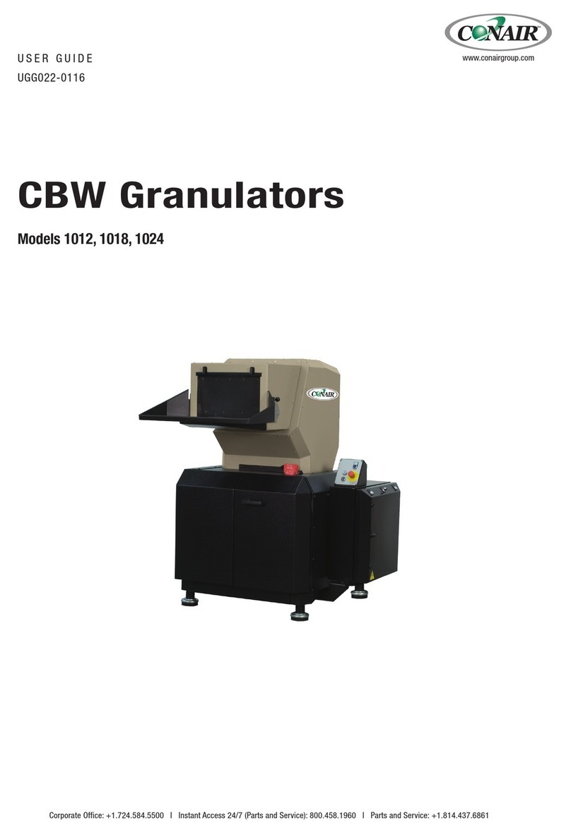
Conair CG-1436 User manual

CGTangential Feed
Granulators
Instant Access
Parts and Service
(800) 458-1960
(814) 437-6861
www.conairnet.com
The Conair Group, Inc.
One Conair Drive
Pittsburgh, PA 15202
Phone: (412) 312-6000
Fax: (412)-312-6320
Model CG-1436
UGG005/0801
Installation
Operation
Maintenance
Troubleshooting

It’s a good idea to record the model and serial number(s) of
your equipment and the date you received it in the User
Guide. Our service department uses this information, along
with the manual number, to provide help for the specific
equipment you installed.
Please keep this User Guide and all manuals, engineering
prints and parts lists together for documentation of your
equipment.
Date:
Manual Number: UGG005/0801
Serial number(s):
Model number(s):
DISCLAIMER: The Conair Group, Inc., shall not be liable for errors
contained in this User Guide or for incidental, consequential dam-
ages in connection with the furnishing, performance or use of this
information. Conair makes no warranty of any kind with regard to
this information, including, but not limited to the implied warranties
of merchantability and fitness for a particular purpose.
Please record your
equipment’s model and
serial number(s) and
the date you received it
in the spaces provided.
Copyright 2001 All rights reserved
THE CONAIR GROUP, INC.

UGG005/0801 CG-1436 Granulator i
Contents
1. Introduction .......................................................................................................................... 1
2. Technical Specification ......................................................................................................2
3. Function description .......................................................................................................... 3
3.1 General .......................................................................................................................... 3
3.2 Safety system ................................................................................................................ 4
4. Safety instructions .............................................................................................................. 6
5. Installation ............................................................................................................................ 7
5.1 Pre-start checks ............................................................................................................ 7
5.2 Electrical connection .................................................................................................... 7
5.3 Opening of hopper, screen box and granule bin .................................................. 9
5.4 Closing the screen box, granule bin and hopper ................................................ 11
6. Operation and maintenance .......................................................................................... 13
6.1 Starting and stopping ................................................................................................ 13
6.2 Inspection .................................................................................................................... 13
6.3 Cleaning ...................................................................................................................... 14
6.4 Troubleshooting .......................................................................................................... 16
7. Service ............................................................................................................................17
7.1 Changing the knives ....................................................................................................17
–Removing the knives .......................................................................................... 17
–Installing the knives ............................................................................................ 18
–Pre-setting of rotating knives ............................................................................ 19
–Installing of pre-set knives .................................................................................. 19
7.2 Sharpening the knives .............................................................................................. 21
–Sharpening of fixed knives ..........................................................................21
–Sharpening of rotating knives ............................................................................ 22
7.3 Transmission ................................................................................................................ 23
7.4 Lubrication .................................................................................................................. 25
7.5 Cutter and motor pulleys .......................................................................................... 26
–Removal/Installing .............................................................................................. 26
8. Spare parts list, Overview .............................................................................................. 29
9. Wiring ........................................................................................................................ 47
10. Layout .......................................................................................................................... 50
11. Accessories, Overview .................................................................................................... 54
11.1 Third fixed knife .......................................................................................................... 55
11.2 Flywheel ...................................................................................................................... 56
11.3 Band conveyor ............................................................................................................ 57
12. Transport and storage .................................................................................................... 59
Appendix ....................................................................................................A-1

UGG005/0801 CG-1436 Granulator INTRODUCTION 1
1. Introduction
This manual applies to the Conair CG-1436 granulator.
Model no. CG-1436 specifies the size of the cutting chamber.
Supplementary designations specify:
U–Machine with extraction fan
KU –Noise encapsulated machine with extraction fan
KUB –Noise encapsulated machine with conveyor
KUP –Noise encapsulated machine for sheet material/profiles
Read the Manual before installing and using the machine.
Be careful when the knives are accessible, they are sharp, and
can cause personal injury!
These Conair granulators are designed for granulating injection molded, blow
molded and extruded plastic parts and scrap.
The size and performance of the granulators are designed to suit the type of
waste material.
Approval must be obtained from Conair for granulating other products
and materials for the warranty conditions to apply.
The granulators are designed so that maintenance and cleaning can be done
quickly and easily, both routine maintenance and changing of materials.
All service must be done by trained service personnel.
This Manual contains instruction for both handling and service.
Chapter 7 contains instructions directed towards service personnel.
Chapter 11 contains accessory equipment for the machine.
Other chapters contain instructions for the operator.
The granulators are delivered with an Instruction Manual and touch-up paint.
Any modifications or conversions of the machines must be approved by Conair.
This is to prevent injuries. The machine warranty and product assurance would
otherwise be rendered void.
Please address any queries to the local Conair representative or Conair
customer service.

CG-1436 Granulator UGG005/0801
2SPECIFICATIONS
2. Technical specifications
ROTOR MOTOR OPTIONS
●=standard o=optional CG-1436
15 Hp {11.0 kW} ●
25 Hp {18.7 kW} o
SPECIFICATION NOTES:
* Throughputs are provided as a capacity guideline
only. Throughput will vary according to the size,
shape, thickness and properties of the material to be
cut, as well as the desired size of the granulate.
Consult Conair for a material test or help determining
the correct granulator model for your application.
†The chart lists standard motor selections. Additional
motor sizes are listed under Motor Options.
‡
Noise level will vary according to material type being
processed and the granulator configuration. These
ranges are based on tests using SPI standards.
Specifications may change without notice. Check with a
Conair representative for the most current information.
MODEL CG-1436
Performance characteristics
Maximum throughput
*
lbs/hr {kg/hr} 1980 {900}
Cutter chamber opening in. {mm} 14 x 36 {350 x 900}
Rotor speed rpm 525
Motor power
†
Hp {kW} 30 {22}
Rotor type 3-blade open rotor
Screen hole sizes 0.16, 0.24, 0.31, 0.39, 0.47, 0.67 and 1 in.
{4, 6, 8, 10, 12, 17 and 25 mm}
Knives
Number of rotating knives 3
Number of fixed knives 2
Dimensions
inches {mm}
A - Height to hopper infeed 54.0 {1370}
B - Width 57.1 {1450}
C - Width with optional blower 69.7 {1770}
D - Depth 63.8 {1620}
E - Feed chamber width 23.6 {600}
F - Feed chamber height 13.8 {350}
Weight
lbs {kg}
Installed 2425 {1100}
Shipping 2646 {1200}
Voltages
Total amps based on motor size‡
15 Hp 25 Hp
208V/3 phase/60 Hz 46.2 74.8
230V/3 phase/60 Hz 41.8 68.0
400V/3 phase/50 Hz 24.0 39.1
460V/3 phase/60 Hz 21.0 34.0
575V/3 phase/60 Hz 16.7 27.1
Noise level
§
With standard soundproofing 80 to 85 dbA
GRANULATOR WITH STANDARD ROBOT/HAND FEED HOPPER
STANDARD 3-BLADE
OPEN ROTOR

The plastic waste is fed into
the hopper (A) and falls
down into the cutting
chamber, where rotating
knives (B) cut the plastics
waste against fixed knives
(C) to granulate.
A perforated screen (D) determines the size of the granulate. The screen is located
in the lower section of the cutting chamber and can easily be changed to give the
desired granulate size.
The granulate passes the screen and falls down through the outlet chute/granule bin
(E) to the outlet pipe (F) for transport onward.
After this, the granulate is ready for re-use in the production machine, or to be trans-
ported to a container for later use.
Granulators with designation “U” are equipped with an extraction blower (G) which
sucks the granulate out to a cyclone for separation of air. On granulator models with
designation “B”, the hopper is equipped with a conveyor belt. The conveyor can be
equipped with a metal detector.
The granulator is easy to clean, with a folding hopper and good accessibility for
maintenance. Knives can be re-sharpened. Grinding is done in a special grinding jig.
(The jig is not included when the granulator is delivered, but is available as an
option.)
A
D
C
B
F
E
G
C
3. Function description
3.1 General
The granulator is designed for grinding plastic waste for recycling.
The plastic waste should be free from metal parts
and contamination before granulating.
The granulator is controlled by
start/stop controls on a control
panel.
UGG005/0801 CG-1436 Granulator DESCRIPTION 3

3.2 Safety system
The granulator has a safety system to prevent access to dangerous components during
operation. The granulator has knives that rotate at high speed. The granulator is there-
fore equipped with a safety system to avoid personal injury. The CG1436 also has
time-delayed opening of the doors.
The safety system must not be changed or modified under any circumstances. If the
safety system of the granulator is changed or modified, the machine can be dangerous
to use, presenting a serious risk of personal injury.
All care and maintenance to the safety system of the granulator must be carried out by
personnel with the necessary knowledge.
If the safety system of the granulator is modified in any way, Conair’s responsibility
under the Machinery Directive ceases to apply.
Only Conair spare parts must be used to replace safety components.
Emergency stop
The granulator has an emergency stop on the control panel. It can also be equipped
with extra emergency stops. The emergency stop is activated by pressing the button.
Reset by turning the button in the direction of the arrow (counterclockwise).
Safety switch
The granulator has one
safety switch of the posi-
tion switch type with break-
ing key, located between
the hopper and the cutter
housing. The safety switch
senses that the hopper seals
tightly against the cutter
housing during operation. If
the hopper opens or
changes position the granu-
lator shuts off.
Check the wiring diagram
to see if your specific gran-
ulator has been equipped
with additional safety
switches.
The doors have a time delay on opening. the dorrs cannot be opened for approximate-
ly 2-3 minutes after the granulator stops. A lamp on the electrical cabinet lights when
the doors open. NOTE! The granulator must be connected to the main power supply
with the main switch in the ON position for the doors to open.
CG-1436 Granulator UGG005/0801
4SAFETY SYSTEM

UGG005/0801 CG-1436 Granulator SAFETY SYSTEM 5
Before starting:
•The hopper must be shut
and locked.
The safety switch senses
whether the hopper seals
tightly against the cutting
chamber during operation.
•The doors must be shut
and the lock knob fully
tightened to stop.
The safety switch senses
whether the doors are shut
properly.
NOTE! The screen box
and granule bin should be
installed and properly shut.

CG-1436 Granulator UGG005/0801
6SAFETY
4. Safety instructions
Conair granulators are designed for granulating injection molded, blow molded and
extruded plastic waste.
The specific technical data for this machine, concerning power and performance- etc.
is described in detail in chapter 2.
The granulator is equipped with safety switches, which are described in
chapter 3.2.
Follow the instructions in this manual to avoid personal injury and damage
to machine components.
Always follow these safety measures when handling the granulator.
•Electrical installation must only be done by a competent electrician!
• Before the granulator is opened for servicing and maintenance.
Always disconnect the power with both the main switch and the
switch on the granulator.
• Never put any part of your body through the granulator openings, unless
both the main switch and the switch on the granulator are in “Off” (0) posi-
tion.
• Be careful with the knives, they are sharp and can cause personal injury.
•If the rotor must be turned manually – do this with great care!
•Observe care when opening or closing the hopper and screenbox, so as not to
trap parts of the body.
•The granulator should not be able to start before the hopper and screen box
are properly closed.
•Never remove protective guards or pipes adjacent to the outlet/granule bin.
•Granulators with belt conveyors! Observe care so that conveyor belts with
dogs do not grip clothing, or arms and feet.
•During maintenance, pull out the plug on the distribution box.
DANGER! High voltage!
This sign is on the door to the distribution box and the connection
boxes.
DANGER! Cutting or pinch risk!
This sign is placed where there is a risk of being cut or pinched.
DANGER! Be careful!
This sign is located by all danger areas, where care and extra atten-
tion is required.

UGG005/0801 CG-1436 Granulator INSTALLATION 7
5. Installation
Read through the whole of chapter 5 before installing the machine! All instructions
must be followed in the given order to avoid injury or damage.
Be careful with the knives, they are sharp and can cause personal injury.
The granulator must only be connected to the mains by a competent electrician.
5.1 Pre-start checks
•Place the granulator in position and adjust the feet of the machine until the granu-
lator stands horizontally.
IMPORTANT! Adjust so that all the machine shoes take up equal loads.
•The unpainted parts of the machine are protected with oil prior to delivery and
transport Clean the granulator from rust protection agent before it is used.
•Check the knife clearance and tightening torque on the bolts for the knives. Refer
to installation of knives in chapter 7.
5.1.1 Two hours after first start
Check the knife clearance again and the tightening torque of the knife retention
screws. Check the screws for both the fixed and rotating knives.
5.1.2 20 - 30 hours after first start
The tension and condition of the V-belts must be checked after 20 - 30 hours
of operation at full load. Checking, adjustment and the V-belt tension is described in
this instruction manual, see chapter 7.3 ”Transmission”.
5.2 Electrical connection
The granulator should be connected by
a competent electrician.
•Connect the granulator to the main
power supply. The wiring diagram
indicates the connection voltage
(Volt) and the fuse sizes (Ammeter).
See chapter 9.
•The granulator is delivered with elec-
trical equipment connected for clock-
wise phase rotation. Check with a
phase sequence indicator and connect
the granulator with clockwise phase
rotation.

CG-1436 Granulator UGG005/0801
8INSTALLATION
Check the direction of rotation of
the granulator motor:
•Open the doors and check that the
hopper is properly closed.
•Close the doora and lock properly.
•Undo and remove the upper
panel on the rear side of the
granulator.
•Make sure that the main switch
on the distribution box is “On”.
•Check that the emergency stop
is not activated.
•Press the Start button.
•Check that the granulator motor
rotates in the direction indicated
by the arrow on the cutter pulley.
•Check that the direction of rotation of the blower corresponds with the
arrow on the cover.
NOTE! The blower blows even if the direction of rotation is wrong.
•Granulator with conveyor belt, – check the direction of the conveyor belt.
If any direction of rotation is incorrect:
•Press the stop button.
•Switch off the main power switch.
•Change two incoming phases.

UGG005/0801 CG-1436 Granulator INSTALLATION 9
D
C
A
5.3 Opening of hopper, screen box and granule bin
Before opening the hopper, granule bin and screen box, switch both
the main switch and granulator switch “Off”.
Be careful when the knives are
accessible. They are sharp and
can cause personal injury.
Opening the hopper
1. Check that the hopper is empty,
then stop the granulator.
2. Switch ”Off” the main switch.
3. Fold up the feed table (A).
4. Open the doors.
5. Undo and fold out the lock
clasps (C) for the hopper.
6. Open/fold the hopper backwards.
NOTE! The hopper is counter-balanced with gas springs so that
it does not fall out of control.
Opening the granule bin and screen box
1. Check that the hopper is empty,
then stop the granulator.
2. Switch ”Off” the main switch.
3. Fold up the feed table (A).
4. Open the doors. Move the door lock
sliding handle to the left to the fully
stop position and open the doors.
5. Undo the quick coupling (D) on the
pipe stub and move it to the side.
6. Undo the granule bin catch. Fold the
spring-loaded lock arms (E) upwards.
NOTE! Hold the granule bin handle at
the same time, so that it does not fall
down out of control.
E
E

CG-1436 Granulator UGG005/0801
10 INSTALLATION
7. First pull the granule bin (F) forwards, then lift the rear edge upwards and out.
8. Undo and fold out the lock clasps
(G) for the screen box (H).
NOTE! Hold the screen box at the same
time, so that it does not fall down out of control.
9. Fold the screen box down. The screen (J) is
now accessible and can be lifted out for
changing or cleaning.
10.Hold the screen box handles and pull the
screen box (H) forwards.
11. Hold the screen arches and handle of the
screen box firmly.
12.Lift the rear edge of the screen box upwards and out.
H
H
D
G
F
J

UGG005/0801 CG-1436 Granulator INSTALLATION 11
5.4 Closing the screen box, granule bin and hopper
NOTE! Before closing, make sure that the mating
surfaces are clean!
There is a pinch risk during closing, be careful.
Close the screen box and install the granule bin
1. Lift the screen box (H).
Hold the screen arches of the screen box and
the handle firmly. Lift up the rear edge of the
screen box and insert the guide heels into the
grooves in the cutting chamber.
Then carefully lower the rear edge of
the screen box.
2. Lift the screen box handle and slide
the screen box in until it stops.
3. Install the screen (J) in the screen box.
Centre and make sure that the cutout
on the screen fits against the pins on
the outer screen arches.
4. Hold the handle and lift the front edge of the
screen box up towards the cutting chamber.
5. Fold the lock clamps (G) against the screen box
in and then fix the screen box with the lock clamps.
6. Install the granule bin (F). Lift up the granule bin
and insert the guide heels on the rear into the
grooves in the cutting chamber.
7. Carefully lower the rear edge of the granule
bin and slide the bin in until it stops.
G
F
H
HJ

CG-1436 Granulator UGG005/0801
12 INSTALLATION
9. Install the quick coupling (D) on the outlet pipe stub.
10.Close the doors.
11. Fold down the feed table (A).
12.Check that the hopper is empty.
13.Switch ”On” the main switch.
14.Start the granulator.
Close the hopper
1. Check and make sure that no granulate lies on the
mating surfaces or flanges.
2. Shut/fold back the hopper.
3. Fold in the lock clamps (C) towards the hopper, then fix
the hopper with the lock clamps.
4. Close the doors (B)..
5. Fold down the feed table (A).
6. Check that the hopper is empty.
7. Switch ”On” the main switch.
8. Start the granulator.
D
C
E
F
B
A
8. Lift up the front edge of the granule bin and lock it. Fold the spring-loaded
lock arms (E) upwards.
E

UGG005/0801 CG-1436 Granulator OPERATION/MAINTENANCE 13
6. Operation and daily maintenance
6.1 Starting and stopping
The main switch is located beneath the control panel
on the front of the granulator.
Starting and stopping is controlled by push buttons
on the control panel.
NOTE! Never stop the granulator before all material in
the hopper and cutting chamber is completely granulated.
Residual material will clog the rotor in the granulator
during re-start. The motor will be overloaded and the
overloading protection will trigger.
6.2 Inspection
There must be no plastic material left in the granulator
when inspection is carried out.
NOTE! All servicing must be done by trained personnel
in order to avoid personal injury and damage to the machine.
Daily inspection
Flaps in the hopper. Check that the flaps are undamaged. Replace damaged
flaps at once. Damaged flaps can drop down into the cutting chamber and
damage the knives. Damaged flaps also entail the risk of material ejection.
Emergency stop. Check the emergency stop function. Start the granulator and
stop it with the emergency stop(s).
Reset. Turn the stop button in the direction of the arrow (counterclockwise).
Weekly inspection
Cables. Check the electric cables of the machine for wear or other damage.
Replace damaged cables at once.
Safety switches. Check the safety switch functions.
The 1436 granulator has one safety switch at the hopper, between the hopper
and cutting chamber.
Check the hopper´s safety switch.
Open the doors, undo and fold out the hopper lock clasps. Close the doors and
try to start the granulator. You should not be able start the granulator before
the hopper and doors are closed.
Check the time delay at opening of the doors. Since the doors have a time
delay for opening the doors should not be
You should not be able to start the granulator when the doors are not closed.
Start
Stop
In operation
Emergency
stop

CG-1436 Granulator UGG005/0801
14 OPERATION/MAINTENANCE
Monthly inspection
Check that the V-belts are undamaged.
Check the V-belt tension every 6 months, see chapter 7.3 “Transmission”.
6.3 Cleaning
Clean at color change, monthly or at least once/300 hours.
Be careful when the hopper has been opened. The knives are now accessible,
they are sharp, and can cause personal injury.
Read the chapter 5.3 “Opening of hopper, screen box and granule bin” which
describes how to open the granulator. Then follow the points below.
1. Check that the hopper is empty, then stop the granulator.
Switch “Off” both the main switch and the switch on
the granulator.
2. Clean the outside of the hopper.
3. Lift out and clean the inner and outer flaps.
4. Fold up the feed table.
5. Open the doors.
6. Undo and fold out the lock clasps for the hopper, open/fold the hopper back-
wards.
NOTE! The hopper is counterbalanced with gas springs so that it does not fall
out of control.
7. Clean the inside of the hopper.
8. Undo the quick coupling on the pipe stub and move it to the side.
9. Remove the granule bin. Undo the granule bin catch. Fold the spring-loaded lock
arms down.
NOTE! Hold the granule bin´s handle at the same time, so that it does not fall
down out of control.
First pull the granule bin forwards, then lift the rear upwards and out.
10.Remove the screen box. Undo and fold out the lock clasps for the screen box,
fold the screen box down.
NOTE! Hold the screen box at the same time, so that it does not fall down out
of control.
11. Lift out the screen.
12.Hold the granule bin handles and pull the granule bin forwards. Hold the screen
box arches and handle firmly. Then lift the rear edge of the screen box forwards,
upwards and out.
13.Clean the granule bin, screen box and screen.

UGG005/0801 CG-1436 Granulator OPERATION/MAINTENANCE 15
14.Clean the cutting chamber inside and outside.
15.Clean any transport pipes, blower and cyclone.
NOTE! If the rotor must be turned manually, do this with great care!
The knives are sharp and can cause personal injury.
NOTE! Use protective goggles and make sure that no material blows
into the safety switches!
16.Granulators with belt conveyors. Clean the belt using a light cleaning agent.
Re-install
NOTE! There is a pinch risk during closing, be careful.
1. Install the screen box. Hold the screen arches on the screen box and the han-
dle firmly. Lift up the rear edge of the screen box and insert the guide heels
into the grooves in the cutting chamber. Then carefully lower the rear edge
of the screen box.
2. Lift the screen box handle and slide the screen
box in until it stops.
3. Install the screen in the screen box. Center and
seat the cutout on the screen against the pins
on the outer screen arches.
4. Hold the handle and lift the front edge of
the screen box up towards the cutter
housing. Then fold the screen box in
and fix it with the lock clamps.
5. Install the granule bin. Lift up the
granule bin and insert the guide
heels on the rear into the grooves
in the cutting chamber.
Carefully lower the rear edge of
the granule bin and slide it in until
it stops. Lift up the front edge and
lock it with the spring-loaded lock arms
(upwards).
6. Install the quick coupling on the outlet pipe stub.
7. Shut/fold back the hopper. Check and make sure that no
granulate lies on the mating surfaces or flanges. Then fold in and fix the hop-
per with the lock clamps.
8. Close the doors.
9. Fold down the feed table.
10.Install the inner and outer flaps in the hopper.
11. Check that the hopper is empty.
12.Switch ”On” the main switch.
13.Start the granulator.

CG-1436 Granulator UGG005/0801
16 OPERATION/MAINTENANCE
6.4 Troubleshooting
The granulator does not start:
•Verify that the emergency stop is not activated. Reset by turning the button(s) in
the direction of the arrow (counterclockwise).
•Check that the doors are properly closed. The granulator will not start if the
doors are not properly closed.
•Check that the hopper is properly closed. The granulator will not start if the hop-
per not is properly closed. Open the door and check that the lock clasps are proper-
ly tightened.
•Check the overload circuit breaker for the motor. The motor has an overload cir-
cuit breaker, F1, in the distribution box, which trips if you jam or overload the
motor. This is indicated in the window (A) which shows “0”.
To reset press the “Reset” button (B). Check that there is
no material left in the granulator before restarting.
•Granulator with blower. Check the blower motor
protection switch.The granulator will not start if the
blower does not start. Check the motor protection switch
Q2 in the distribution box.
If the motor protection switch has switched off the switch will be in position “0”.
Reset the switch button to position “1”. Check that there is no material left in the
granulator before restarting.
•Granulator with band conveyor. If the band conveyor does not start – check the
band conveyor´s motor protection switch. The band conveyor has a motor protec-
tion switch, Q3, in the distribution cabinet, which trips if you jam or overload the
conveyor belt.
If the motor protection switch has switched ”off” the switch will be in position ”0”.
Reset the switch button in position “l”. Check that there is no material left on the
band before restarting.
•Check the granulator knives and knife tolerance.
If the granulator knives are blunt and unsharpened, or if the knife clearance is
incorrect, this can result in stoppage. The granulator motor overload circuit breaker
will trip. Check the knives. Sharpen or replace the knives, or adjust the knife clear-
ance, see next chapter.
Also check the wiring diagram in chapter 9; supplements and deviations may be applicable.
The doors do not open:
•Verify that the emergency stop is not activated. Reset by turning the button(s) in
the direction of the arrow (counterclockwise).
•Verify that the main power is on and the main switch is in the ON position.
•The doors are on a time delay. Wait 2-3 minutes until the lamp on the distribution
box lights. Try opening the doors again.
A
B
Table of contents
Other Conair Industrial Equipment manuals

Conair
Conair DeDuster C-50 User manual

Conair
Conair SHH Series User manual

Conair
Conair S Series User manual

Conair
Conair GT420 User manual

Conair
Conair Viper User manual

Conair
Conair TF Series User manual

Conair
Conair Air Wash 50 User manual

Conair
Conair CBW 1012 User manual

Conair
Conair CH Series User manual
Popular Industrial Equipment manuals by other brands

Siemens
Siemens MODULARIS Uro Plus Service instructions

Bona
Bona HD Belt Service instructions

Blohm + Voss Oil Tools
Blohm + Voss Oil Tools FloorHand 9GF-1102 Technical documentation

STEPCRAFT
STEPCRAFT M Series Construction manual

Panduit
Panduit JBP1D installation instructions

AMS
AMS ALF19 Series operating instructions