Congatec Qseven conga-QMX6 User manual

Qseven®conga-QMX6
Freescale®i.MX6 ARM®Cortex A9 processor with Ultra Low Power Consumption
User’s Guide
Revision 0.3 (Preliminary)

Copyright © 2013 congatec AG QMX6m03 2/63
Revision History
Revision Date (yyyy.mm.dd) Author Changes
0.1 2013.03.28 AEM • Preliminary release
0.2 2013.11.05 AEM • Corrected the LVDS data rates/resolutions supported in sections 2.1 “Feature List“ and 5.8 “LVDS”.
• Added information about the Atheros Quadcomm Ethernet PHY for conga-QMX6 revision B.0 in sections 2.1 “Feature List” and 5.3 “Gigabit
Ethernet”.
• Updated section 4 “Heatspreader”. Added additional heatspreader variants.
• Updated section 5.2 “UART”. Updated section 5.13 “Manufacturing/Jtag Interface”.
• Added pin descriptions for the onboard UART connector and the RS-232 adapter cable in section 10.1 “UART/RS-232 Debug Port”.
• Added section 10.3 “JTAG Interface”.
0.3 2014.02.28 AEM • Added the new Ethernet PHY (Qualcomm Atheros) for conga-QMX6 revision B.x to relevant sections.
• Changed the eMMC value of industrial variants from 2G to 4G
• Deleted the row “RSVD” from table 23 “ Manufacturing Signal Description”.
• Edited section 5.2 “UART” and added caution statement.
• Updated the whole document.

Copyright © 2013 congatec AG QMX6m03 3/63
Preface
This user’s guide provides information about the components, features, connectors and signals available on the conga-QMX6. It is one of four
documents that you should refer to when designing an i.MX6 based Qseven® application. The other reference documents that should be used
include the following:
Qseven®Design Guide
Qseven® Specication
i.MX6 Applications Processor Reference Manual (available at www.freescale.com)
The links to these documents can be found on the congatec AG website at www.congatec.com
Disclaimer
The information contained within this user’s guide, including but not limited to any product specication, is subject to change without notice.
congatec AG provides no warranty with regard to this user’s guide or any other information contained herein and hereby expressly disclaims
any implied warranties of merchantability or tness for any particular purpose with regard to any of the foregoing. congatec AG assumes
no liability for any damages incurred directly or indirectly from any technical or typographical errors or omissions contained herein or for
discrepancies between the product and the user’s guide. In no event shall congatec AG be liable for any incidental, consequential, special, or
exemplary damages, whether based on tort, contract or otherwise, arising out of or in connection with this user’s guide or any other information
contained herein or the use thereof.
Intended Audience
This user’s guide is intended for technically qualied personnel. It is not intended for general audiences.

Copyright © 2013 congatec AG QMX6m03 4/63
Symbols
The following symbols are used in this user’s guide:
Warning
Warnings indicate conditions that, if not observed, can cause personal injury.
Caution
Cautions warn the user about how to prevent damage to hardware or loss of data.
Note
Notes call attention to important information that should be observed.

Copyright © 2013 congatec AG QMX6m03 5/63
Terminology
Term Description
PCI Express (PCIe) Peripheral Component Interface Express – next-generation high speed Serialized I/O bus
ARM Advanced RISC Machine
JTAG Joint Test Action Group
eCSPI Enhanced Congurable Serial Peripheral Interface
MIPI Mobile Industry CPU Interface
GPIO General Purpose Input Output
RGMII Reduced Gigabit Media Independent Interface
PCI Express Lane One PCI Express Lane is a set of 4 signals that contains two differential lines for transmitting and two differential lines for Receiving. Clocking information is embedded
into the data stream.
x1, x2, x4, x8, x16 x1 refers to one PCI Express Lane of basic bandwidth; x2 to a collection of two PCI Express Lanes; etc.. Also referred to as x1, x2, x4, x8, or x16 link.
PCI Express Mini Card PCI Express Mini Card add-in card is a small size unique form factor optimized for mobile computing platforms.
eMMC Embedded Multi Media Card is a non-volatile memory system, which frees the processor from low level ash memory management.
SDIO card SDIO (Secure Digital Input Output) is a non-volatile memory card format developed for use in portable devices.
USB Universal Serial Bus
SATA Serial AT Attachment: serial-interface standard for hard disks
HDA High Denition Audio
HDMI High Denition Multimedia Interface. HDMI supports standard, enhanced, or high-denition video, plus multi-channel digital audio on a single cable.
TMDS Transition Minimized Differential Signaling. TMDS is a signaling interface dened by Silicon Image that is used for DVI and HDMI.
DVI Digital Visual Interface is a video interface standard developed by the Digital Display Working Group (DDWG).
I²C Bus Inter-Integrated Circuit Bus: is a simple two-wire bus with a software-dened protocol that was developed to provide the communications link between integrated
circuits in a system.
SM Bus System Management Bus: is a popular derivative of the I²C-bus.
SPI Bus Serial Peripheral Interface is a synchronous serial data link standard named by Motorola that operates in full duplex mode.
CAN Bus Controller-area network is a vehicle bus standard designed to allow microcontrollers and devices to communicate with each other within a vehicle without a host
computer.
AMBA Advanced Microcontroller Bus Architecture
IOMUX Input Output Multiplexer
GbE Gigabit Ethernet
LVDS Low-Voltage Differential Signaling
DDC Display Data Channel is an I²C bus interface between a display and a graphics adapter.
N.C. Not connected
N.A. Not available
T.B.D. To be determined

Copyright © 2013 congatec AG QMX6m03 6/63
Copyright Notice
Copyright © 2010, congatec AG. All rights reserved. All text, pictures and graphics are protected by copyrights. No copying is permitted without
written permission from congatec AG.
congatec AG has made every attempt to ensure that the information in this document is accurate yet the information contained within is
supplied “as-is”.
Trademarks
Product names, logos, brands, and other trademarks featured or referred to within this user’s guide, or the congatec website, are the property
of their respective trademark holders. These trademark holders are not afliated with congatec AG, our products, or our website.
Warranty
congatec AG makes no representation, warranty or guaranty, express or implied regarding the products except its standard form of limited
warranty (“Limited Warranty”) per the terms and conditions of the congatec entity, which the product is delivered from. These terms and
conditions can be downloaded from www.congatec.com. congatec AG may in its sole discretion modify its Limited Warranty at any time and
from time to time.
The products may include software. Use of the software is subject to the terms and conditions set out in the respective owner’s license
agreements, which are available at www.congatec.com and/or upon request.
Beginning on the date of shipment to its direct customer and continuing for the published warranty period, congatec AG represents that the
products are new and warrants that each product failing to function properly under normal use, due to a defect in materials or workmanship or
due to non conformance to the agreed upon specications, will be repaired or exchanged, at congatec’s option and expense.
Customer will obtain a Return Material Authorization (“RMA”) number from congatec AG prior to returning the non conforming product freight
prepaid. congatec AG will pay for transporting the repaired or exchanged product to the customer.
Repaired, replaced or exchanged product will be warranted for the repair warranty period in effect as of the date the repaired, exchanged
or replaced product is shipped by congatec, or the remainder of the original warranty, whichever is longer. This Limited Warranty extends to
congatec’s direct customer only and is not assignable or transferable.
Except as set forth in writing in the Limited Warranty, congatec makes no performance representations, warranties, or guarantees, either
express or implied, oral or written, with respect to the products, including without limitation any implied warranty (a) of merchantability, (b) of
tness for a particular purpose, or (c) arising from course of performance, course of dealing, or usage of trade.

Copyright © 2013 congatec AG QMX6m03 7/63
congatec AG shall in no event be liable to the end user for collateral or consequential damages of any kind. congatec shall not otherwise be
liable for loss, damage or expense directly or indirectly arising from the use of the product or from any other cause. The sole and exclusive
remedy against congatec, whether a claim sound in contract, warranty, tort or any other legal theory, shall be repair or replacement of the
product only.
Certication
congatec AG is certied to DIN EN ISO 9001:2008 standard.
Technical Support
congatec AG technicians and engineers are committed to providing the best possible technical support for our customers so that our products
can be easily used and implemented. We request that you rst visit our website at www.congatec.com for the latest documentation, utilities and
drivers, which have been made available to assist you. If you still require assistance after visiting our website then contact our technical support
Lead-Free Designs (RoHS)
All congatec AG designs are created from lead-free components and are completely RoHS compliant.
Electrostatic Sensitive Device
All congatec AG products are electrostatic sensitive devices and are packaged accordingly. Do not open or handle a congatec AG product
except at an electrostatic-free workstation. Additionally, do not ship or store congatec AG products near strong electrostatic, electromagnetic,
magnetic, or radioactive elds unless the device is contained within its original manufacturer’s packaging. Be aware that failure to comply with
these guidelines will void the congatec AG Limited Warranty.
C
E
R
T
I
F
I
C
A
T
I
O
N
I
S
O
9
0
0
1
TM

Copyright © 2013 congatec AG QMX6m03 8/63
Contents
1 INTRODUCTION ..................................................................... 11
2 Specications........................................................................... 13
2.1 Feature List .............................................................................. 13
2.2 Supported Operating Systems................................................. 14
2.3 Mechanical Dimensions ........................................................... 14
2.4 Supply Voltage Standard Power .............................................. 15
2.4.1 Electrical Characteristics.......................................................... 15
2.4.2 Rise Time ................................................................................. 15
2.5 Power Consumption................................................................. 16
2.5.1 Freescale® i.MX6 Cortex A9 1.0 GHz Single Core 512kB L2 cache
17
2.5.2 Freescale® i.MX6 Cortex A9 1.0 GHz Dual Lite 512kB L2 cache17
2.5.3 Freescale® i.MX6 Cortex A9 1.0 GHz Dual Core 1MB L2 cache18
2.5.4 Freescale® i.MX6 Cortex A9 1.0 GHz Quad Core 1MB L2 cache18
2.5.5 Freescale® i.MX6 Cortex A9 1.0 GHz Quad Core 1MB L2 cache18
2.5.6 Freescale® i.MX6 Cortex A9 800 MHz Single Core 512kB L2
cache (2GB eMMC) ................................................................. 19
2.5.7 Freescale® i.MX6 Cortex A9 800 MHz Dual Lite 512kB L2 cache
(2GB eMMC)............................................................................ 19
2.5.8 Freescale® i.MX6 Cortex A9 800 MHz Dual Core 1MB L2 cache
(2GB eMMC)............................................................................ 19
2.5.9 Freescale® i.MX6 Cortex A9 800 MHz Quad Core 1MB L2 cache
(2GB eMMC)............................................................................ 20
2.6 Supply Voltage Battery Power ................................................. 20
2.6.1 CMOS Battery Power Consumption ........................................ 20
2.7 Environmental Specications................................................... 21
3 Block Diagram.......................................................................... 22
4 Heatspreader ........................................................................... 23
4.1 Heatspreader Dimensions ....................................................... 24
5 Connector Subsystems............................................................ 26
5.1 PCI Express™ ......................................................................... 27
5.2 UART/RS-232 .......................................................................... 27
5.3 Gigabit Ethernet ....................................................................... 28
5.4 SATA ........................................................................................ 28
5.5 USB 2.0.................................................................................... 28
5.6 SD/SDIO/MMC......................................................................... 29
5.7 HDA/I2S/AC’97 ........................................................................ 29
5.8 LVDS........................................................................................ 29
5.9 HDMI........................................................................................ 30
5.10 LPC/GPIO ................................................................................ 30
5.11 SPI ........................................................................................... 31
5.12 CAN Bus .................................................................................. 31
5.13 Manufacturing/JTAG Interface ................................................. 31
5.14 Power Control .......................................................................... 31
5.15 Power Management................................................................. 33
5.16 Watchdog................................................................................. 33
5.17 I2C Bus .................................................................................... 34
6 Additional Features .................................................................. 35
6.1 High Assurance Boot (HAB)..................................................... 35
6.2 Dedicated Hardware Accelerators ........................................... 35
6.3 Power Management................................................................. 35
6.4 Dynamic Voltage and Frequency Scaling ................................ 35
6.5 Smart Speed Technology......................................................... 36
6.6 Suspend Mode......................................................................... 36
7 ARM Technologies ................................................................... 37
7.1 Media Processing Engine (MPE-NEON) ................................ 37
7.2 Jazelle DBX ............................................................................. 37
7.3 TrustZone................................................................................. 37
7.4 Floating Point Unit.................................................................... 37
8 conga Tech Notes .................................................................... 38
8.1 Freescale®i.MX6 Processor Features ..................................... 38
8.1.1 Temperature Monitor (TEMPMON).......................................... 38
8.2 Thermal Management.............................................................. 38
8.3 Audio Mux ................................................................................ 39
8.4 LVDS Bridge ............................................................................ 39
Copyright © 2013 congatec AG QMX6m03
9/63
8.5 USB Port Connections ............................................................. 39
9 Interface - Signal Descriptions and Pinout Tables ................... 41
9.1 PCI Express™ ......................................................................... 45
9.2 UART ....................................................................................... 45
9.3 Gigabit Ethernet ....................................................................... 46
9.4 SATA ........................................................................................ 47
9.5 USB 2.0.................................................................................... 47
9.6 SDIO/MMC............................................................................... 49
9.7 HDA /I2S /SPDIF...................................................................... 50
9.8 LVDS........................................................................................ 50
9.9 DisplayPort............................................................................... 52
9.10 HDMI........................................................................................ 52
9.11 LPC/GPIO ................................................................................ 53
9.12 SPI ........................................................................................... 54
9.13 CAN Bus .................................................................................. 54
9.14 Input Power.............................................................................. 54
9.15 Power Control .......................................................................... 55
9.16 Power Management................................................................. 55
9.17 Miscellaneous .......................................................................... 56
9.18 Manufacturing/JTAG Interface ................................................. 57
9.19 Thermal Management.............................................................. 58
9.20 Fan Control .............................................................................. 58
9.21 Bootstrap Signals..................................................................... 59
10 Onboard Interfaces and Devices ............................................. 60
10.1 UART/RS-232 Debug Port....................................................... 60
10.2 MIPI/CMOS Camera ................................................................ 60
10.3 JTAG Interface ......................................................................... 61
10.4 SPI Flash ................................................................................. 61
10.5 Android Buttons ....................................................................... 61
10.6 DDR3 Memory ......................................................................... 61
10.7 eMMC ...................................................................................... 62
10.8 Micro SD .................................................................................. 62
11 Industry Specications ............................................................. 63

Copyright © 2013 congatec AG QMX6m03 10/63
List of Tables
Table 1 Commercial variants ................................................................ 12
Table 2 Industrial Variants .................................................................... 12
Table 3 Feature Summary .................................................................... 13
Table 4 Signal Tables Terminology Descriptions .................................. 41
Table 5 Edge Finger Pinout .................................................................. 42
Table 6 PCI Express Signal Descriptions ............................................. 45
Table 7 UART Signal Descriptions........................................................ 45
Table 8 Ethernet Signal Descriptions.................................................... 46
Table 9 SATA Signal Descriptions......................................................... 47
Table 10 USB Signal Descriptions.......................................................... 47
Table 11 SDIO Signal Descriptions ........................................................ 49
Table 12 HDA/AC’97 Signal Descriptions............................................... 50
Table 13 LVDS Signal Descriptions ........................................................ 50
Table 14 DisplayPort Signal Descriptions............................................... 52
Table 15 HDMI Signal Descriptions ........................................................ 52
Table 16 LPC/GPIO Signal Descriptions ................................................ 53
Table 17 SPI Interface Signal Descriptions ............................................ 54
Table 18 CAN Bus Signal Descriptions .................................................. 54
Table 19 Input Power Signal Descriptions .............................................. 54
Table 20 Power Control Signal Descriptions .......................................... 55
Table 21 Power Management Signal Descriptions ................................. 55
Table 22 Miscellaneous Signal Descriptions .......................................... 56
Table 23 Manufacturing Signal Descriptions .......................................... 57
Table 24 Thermal Management Signal Descriptions .............................. 58
Table 25 Fan Control Signal Descriptions .............................................. 58
Table 26 Bootstrap Signal Descriptions.................................................. 59
Table 27 UART Signal Descriptions........................................................ 60
Table 28 Android Button Signal Descriptions ......................................... 61

Copyright © 2013 congatec AG QMX6m03 11/63
1 INTRODUCTION
Qseven®Concept
The Qseven®concept is an off-the-shelf, multi vendor, Single-Board-Computer that integrates all the core components of a common PC and is
mounted onto an application specic carrier board. Qseven® modules have a standardized form factor of 70mm x 70mm and a specied pinout
based on the high speed MXM system connector. The pinout remains the same regardless of the vendor. The Qseven®module provides the
functional requirements for an embedded application. These functions include, but are not limited to graphics, sound, mass storage, network
interface and multiple USB ports.
A single ruggedized MXM connector provides the carrier board interface to carry all the I/O signals to and from the Qseven®module. This MXM
connector is a well known and proven high speed signal interface connector that is commonly used for high speed PCI Express graphics cards
in notebooks.
Carrier board designers can utilize as little or as many of the I/O interfaces as deemed necessary. The carrier board can therefore provide all
the interface connectors required to attach the system to the application specic peripherals. This versatility allows the designer to create a
dense and optimized package, which results in a more reliable product while simplifying system integration.
The Qseven®evaluation carrier board provides carrier board designers with a reference design platform and the opportunity to test all the
Qseven®I/O interfaces available and then choose what are suitable for their application. Qseven®applications are scalable, which means once
a carrier board has been created there is the ability to diversify the product range through the use of different performance class Qseven®
modules. Simply unplug one module and replace it with another; no need to redesign the carrier board.
This document describes the features available on the Qseven®evaluation carrier board. Additionally, the schematics for the Qseven®evaluation
carrier board can be found on the congatec website.
Note
The conga-QMX6 design is based on the Qseven specication 2.0 and in revision B.0 design, we took into consideration the Qseven Specication
2.0 Errata.

Copyright © 2013 congatec AG QMX6m03 12/63
conga-QMX6 Options Information
The conga-QMX6 is currently available in nine variants (ve commercial and four industrial). This user’s guide describes the features these
variants offer. Below you will nd an order table showing the base conguration modules that are currently offered by congatec AG. For more
information about additional conga-QMX6 variants offered by congatec, contact your local congatec sales representative or visit the congatec
website at www.congatec.com.
Table 1 Commercial variants
Part-No. 016100 016101 016102 016103 016104
Processor Freescale® i.MX6 Cortex A9
1.0 GHz Single Core
Freescale® i.MX6 Cortex A9
1.0 GHz Dual Lite
Freescale® i.MX6 Cortex A9
1.0 GHz Dual Core
Freescale® i.MX6 Cortex A9
1.0 GHz Quad Core
Freescale® i.MX6 Cortex A9
1.0 GHz Quad Core
L2 Cache 512 kB 512 kB 1 MB 1 MB 1 MB
Onboard Memory 1GB DDR3 1GB DDR3 1GB DDR3 1GB DDR3 2GB DDR3
eMMC up to 8GB 4GB 4GB 4GB 4GB 4GB
PCI Express Lane Yes Yes Yes Yes Yes
CAN Bus Yes Yes Yes Yes Yes
Gigabit Ethernet Yes Yes Yes Yes Yes
SATA No No Yes Yes Yes
Table 2 Industrial Variants
Part-No. 016110 016111 016112 016113
Processor Freescale® i.MX6 Cortex A9
800 MHz Single Core
Freescale® i.MX6 Cortex A9
800 MHz Dual Lite
Freescale® i.MX6 Cortex A9
800 MHz Dual Core
Freescale® i.MX6 Cortex A9
800 MHz Quad Core
L2 Cache 512 kB 512 kB 1 MB 1 MB
Onboard Memory 1GB DDR3 1GB DDR3 1GB DDR3 1GB DDR3
eMMC up to 8GB 4GB 4GB 4GB 4GB
PCI Express Lane Yes Yes Yes Yes
CAN Bus Yes Yes Yes Yes
Gigabit Ethernet Yes Yes Yes Yes
SATA No No Yes Yes
Caution
Do not alter the conga-QMX6 boot fuse settings. These fuse settings are already programmed during production process and are not protected
against alteration. Changing the boot fuse settings will void the congatec AG warranty.

Copyright © 2013 congatec AG QMX6m03 13/63
2 Specications
2.1 Feature List
Table 3 Feature Summary
Form Factor Based on Qseven® form factor specication revision 2.0
Processor Freescale® i.MX6 Cortex A9
Memory up to 2 GB onboard DDR3 memory
Audio I2S format supported
Ethernet Gigabit Ethernet (Qualcomm Atheros PHY) on conga-QMX6 rev B.x. Earlier conga-QMX6 variants are equipped with Micrel KSZ9031 PHY.
Graphics Options Integrated video graphic subsystem consisting of Video Processing Unit (VPU), Graphic Processing Unit (3D GPU, 2D GPU, Open VG), Image
Processing Unit, Display interface bridges (LVDS, HDMI, MIPI/DSI).
• 1x HDMI 1.4.
• Two LVDS channels driven by the LVDS display bridge. Support:
• Single channel LVDS interface : 1 x 18 bpp or 1 x 24 bpp (up to 85 MHz per
interface e.g 1366x768 @ 60Hz + 35% blanking)
• Dual channel LVDS interface: 2 x 18 bpp OR 2 x 24 bpp (up to 170 MHz pixel
clock e.g 1600x1200 @ 60 Hz + 35% blanking).
NOTE:
Supports three independent displays (must be 2x single channel LVDS and 1x HDMI)
• Video Decode Acceleration:
MPEG2 MP, HP
MPEG4 SP
H.264
VC-1
DivX
Peripheral
Interfaces
• 1x Serial ATA® Gen 2 (3GB/s)
• 1x SDIO
• x1 PCI Express Lane Gen 2.0 offering up to 5 GB/s
• 5x USB 2.0 ports (4x USB 2.0 hosts and 1x USB 2.0 OTG)
• I2S Bus
• SPI
• CAN
• 8x GPIOs
• 3x I²C fast mode, multi-master (two shared I²C buses and
one unshared bus)
• 1x UART (fully featured UART with control signals,
supported on the MXM connector)
• 2x RS-232 interfaces supported onboard the conga-QMX6
via RS232 transceiver.
Onboard Interfaces
and Devices
• Android Buttons
• JTAG
• RS-232 Debug Port
• SPI Flash (contains the bootloader)
• DDR3 SDRAM memory (up to 2 GB)
• Micro-SD Socket
• eMMC module (4GB onboard)
Bootloader Pre-installed open-source bootloader (U-boot)
Power Management Yes.
Note
Some of the features mentioned in the above feature summary are optional. Check the article number of your module and compare it to the
conga-QMX6 options information list on page 12 of this user’s guide to determine what options are available on your particular module.

Copyright © 2013 congatec AG QMX6m03 14/63
2.2 Supported Operating Systems
The conga-QMX6 supports the following operating systems.
• Microsoft®Windows®Embedded Compact 7
• Android
• Linux
2.3 Mechanical Dimensions
• 70.0 mm x 70.0 mm @ (2 ¾” x 2 ¾”)
• The Qseven™ module, including the heatspreader plate, PCB thickness and bottom components, is up to approximately 12mm thick.
Heatspeader
Qseven Module PCB
Carrier Board PCB
Dimension is dependent
on connector height used
Dimension is dependent
on connector height used
All measurements are in millimeters
All dimensions without tolerance ±0.2mm
Rear View of Qseven Module
2.00
1.20 ±0.1
6.00 8.00

Copyright © 2013 congatec AG QMX6m03 15/63
2.4 Supply Voltage Standard Power
• 5V DC ± 5%
The dynamic range shall not exceed the static range.
2.4.1 Electrical Characteristics
Characteristics Min. Typ. Max. Units Comment
5V Voltage ± 5% 4.75 5.00 5.25 Vdc
Ripple - - ± 50 mVPP 0-20MHz
Current
5V_SB Voltage ± 5% 4.75 5.00 5.25 Vdc
Ripple ± 50 mVPP
2.4.2 Rise Time
The input voltages shall rise from 10% of nominal to 90% of nominal at a minimum slope of 250V/s. The smooth turn-on requires that during
the 10% to 90% portion of the rise time, the slope of the turn-on waveform must be positive.
Note
For information about the input power sequencing of the Qseven®module, refer to the Qseven® specication.
Nominal Static Range
Dynamic Range
Absolute Minimum
Absolute Maximum5.25V
4.75V
5V
5.05V
4.95V

Copyright © 2013 congatec AG QMX6m03 16/63
2.5 Power Consumption
The power consumption values listed in this document were measured under a controlled environment. The hardware used for testing includes
a conga-QMX6 module, carrier board for Qseven ARM, TFT monitor, micro-SD card and USB keyboard. The carrier board was powered
externally by a power supply unit so that it does not inuence the power consumption value that is measured for the module. The USB keyboard
was detached once the module was congured within the OS. All recorded values were averaged over a 30 second time period. The modules
were cooled by the heatspreader specic to the module variants
Each module was measured while running 32 bit Linaro Ubuntu 11.10. To measure the worst case power consumption, the cooling solution
was removed and the CPU core temperature was allowed to run between 95° and 100°C at 100% workload. The peak current value was then
recorded. This value should be taken into consideration when designing the system’s power supply to ensure that the power supply is sufcient
during worst case scenarios.
Power consumption values were recorded during the following stages:
Linaro Ubuntu 11.10 (32 bit)
• Desktop Idle
• 100% CPU workload
• 100% CPU workload at approximately 100°C peak power consumption
Note
With the linux stress tool, we stressed the CPU to maximum frequency.

Copyright © 2013 congatec AG QMX6m03 17/63
Processor Information
The tables below provide additional information about the different variants offered by the conga-QMX6.
2.5.1 Freescale®i.MX6 Cortex A9 1.0 GHz Single Core 512kB L2 cache
With 4GB onboard eMMC
conga-QMX6 Art. No. 016100 Freescale®i.MX6 Cortex A9 1.0 GHz 512kB L2 cache
40nm
Layout Rev. QMX6LB1 /Bootloader Rev. QMX6Rx07
Memory Size 1GB onboard
Operating System Ubuntu
Power State Desktop Idle 100% workload Max. Power Consumption
Power consumption (measured in Amperes/Watts) 0.22 A/ 1.1 W 0.34 A/ 1.7 W 0.46 A/2.3 W
2.5.2 Freescale®i.MX6 Cortex A9 1.0 GHz Dual Lite 512kB L2 cache
With 4GB onboard eMMC
conga-QMX6 Art. No. 016101 Freescale®i.MX6 Cortex A9 1.0 GHz 512kB L2 cache
40nm
Layout Rev. QMX6LB1 /Bootloader Rev. QMX6Rx07
Memory Size 1GB onboard
Operating System Ubuntu
Power State Desktop Idle 100% workload Max. Power Consumption
Power consumption (measured in Amperes/Watts) 0.26 A/ 1.3 W 0.44 A/ 2.2 W 0.66 A/ 3.3 W

Copyright © 2013 congatec AG QMX6m03 18/63
2.5.3 Freescale®i.MX6 Cortex A9 1.0 GHz Dual Core 1MB L2 cache
With 4GB onboard eMMC
conga-QMX6 Art. No. 016102 Freescale®i.MX6 Cortex A9 1.0 GHz 1MB L2 cache
40nm
Layout Rev. QMX6LB1 /Bootloader Rev. QMX6Rx07
Memory Size 1GB onboard
Operating System Ubuntu
Power State Desktop Idle 100% workload Max. Power Consumption
Power consumption (measured in Amperes/Watts) 0.28 A/ 1.4 W 0.5 A/ 2.5 W 0.7 A/ 3.2 W
2.5.4 Freescale®i.MX6 Cortex A9 1.0 GHz Quad Core 1MB L2 cache
With 4GB onboard eMMC
conga-QMX6 Art. No. 016103 Freescale®i.MX6 Cortex A9 1.0 GHz 1MB L2 cache
40nm
Layout Rev. QMX6LB1 /Bootloader Rev. QMX6Rx07
Memory Size 1GB onboard
Operating System Ubuntu
Power State Desktop Idle 100% workload Max. Power Consumption
Power consumption (measured in Amperes/Watts) 0.3 A/ 1.5 W 0.72 A/ 3.6 W 0.92 A/ 4.6 W
2.5.5 Freescale®i.MX6 Cortex A9 1.0 GHz Quad Core 1MB L2 cache
With 4GB onboard eMMC
conga-QMX6 Art. No. 016104 Freescale®i.MX6 Cortex A9 1.0 GHz 1MB L2 cache
40nm
Layout Rev. QMX6LB1 /Bootloader Rev. QMX6Rx07
Memory Size 2GB onboard
Operating System Ubuntu
Power State Desktop Idle 100% workload Max. Power Consumption
Power consumption (measured in Amperes/Watts) 0.3 A/ 1.5 W 0.74 A/ 3.7 W 0.94 A/ 4.7 W

Copyright © 2013 congatec AG QMX6m03
19/63
2.5.6 Freescale®i.MX6 Cortex A9 800 MHz Single Core 512kB L2 cache (2GB eMMC)
With 2GB onboard eMMC
conga-QMX6 Art. No. 016110 Freescale®i.MX6 Cortex A9 800 MHz 512kB L2 cache
40nm
Layout Rev. QMX6LB1 /Bootloader Rev. QMX6Rx07
Memory Size 1GB onboard
Operating System Ubuntu
Power State Desktop Idle 100% workload Max. Power Consumption
Power consumption (measured in Amperes/Watts) 0.24 A/ 1.2 W 0.30 A/ 1.5 W 0.48 A/ 2.1 W
2.5.7 Freescale®i.MX6 Cortex A9 800 MHz Dual Lite 512kB L2 cache (2GB eMMC)
With 2GB onboard eMMC
conga-QMX6 Art. No. 016111 Freescale®i.MX6 Cortex A9 800 MHz 512kB L2 cache
40nm
Layout Rev. QMX6LB1 /Bootloader Rev. QMX6Rx07
Memory Size 1GB onboard
Operating System Ubuntu
Power State Desktop Idle 100% workload Max. Power Consumption
Power consumption (measured in Amperes/Watts) TBD A/ W TBD A/ W TBD A/ W
2.5.8 Freescale®i.MX6 Cortex A9 800 MHz Dual Core 1MB L2 cache (2GB eMMC)
With 2GB onboard eMMC
conga-QMX6 Art. No. 016112 Freescale®i.MX6 Cortex A9 800 MHz 1MB L2 cache
40nm
Layout Rev. QMX6LB1 /Bootloader Rev. QMX6Rx07
Memory Size 1GB onboard
Operating System Ubuntu
Power State Desktop Idle 100% workload Max. Power Consumption
Power consumption (measured in Amperes/Watts) 0.30 A/ 1.5W 0.42 A/ 2.1 W 0.60 A/ 3.0 W

Copyright © 2013 congatec AG QMX6m03 20/63
2.5.9 Freescale®i.MX6 Cortex A9 800 MHz Quad Core 1MB L2 cache (2GB eMMC)
With 2GB onboard eMMC
conga-QMX6 Art. No. 016113 Freescale®i.MX6 Cortex A9 800 MHz 1MB L2 cache
40nm
Layout Rev. QMX6LB1 /Bootloader Rev. QMX6Rx07
Memory Size 1GB onboard
Operating System Ubuntu
Power State Desktop Idle 100% workload Max. Power Consumption
Power consumption (measured in Amperes/Watts) 0.30 A/ 1.5 W 0.54 A/ 2.7 W 0.72 A/ 3.6 W
Note
All recorded power consumption values are approximate and only valid for the controlled environment described earlier. 100% workload refers
to the CPU workload and not the maximum workload of the complete module. Power consumption results will vary depending on the workload
of other components such as graphics engine, memory, etc.
2.6 Supply Voltage Battery Power
• 2.0V-3.6V DC
• Typical 3V DC
2.6.1 CMOS Battery Power Consumption
RTC @ 20ºC Voltage Current
RTC onboard the conga-QMX6 module 3V DC 1.45 µA
The CMOS battery power consumption value listed above should not be used to calculate CMOS battery lifetime. You should measure the
CMOS battery power consumption in your customer specic application in worst case conditions, for example during high temperature and
high battery voltage. The self-discharge of the battery must also be considered when determining CMOS battery lifetime. For more information
about calculating CMOS battery lifetime refer to application note AN9_RTC_Battery_Lifetime.pdf, which can be found on the congatec AG
website at www.congatec.com.
Note
To improve the lifetime of the CMOS battery, congatec implemented an external real time clock onboard the conga-QMX6 module.
Other manuals for Qseven conga-QMX6
1
Table of contents
Other Congatec Computer Hardware manuals

Congatec
Congatec COM Express conga-TCV2 User manual

Congatec
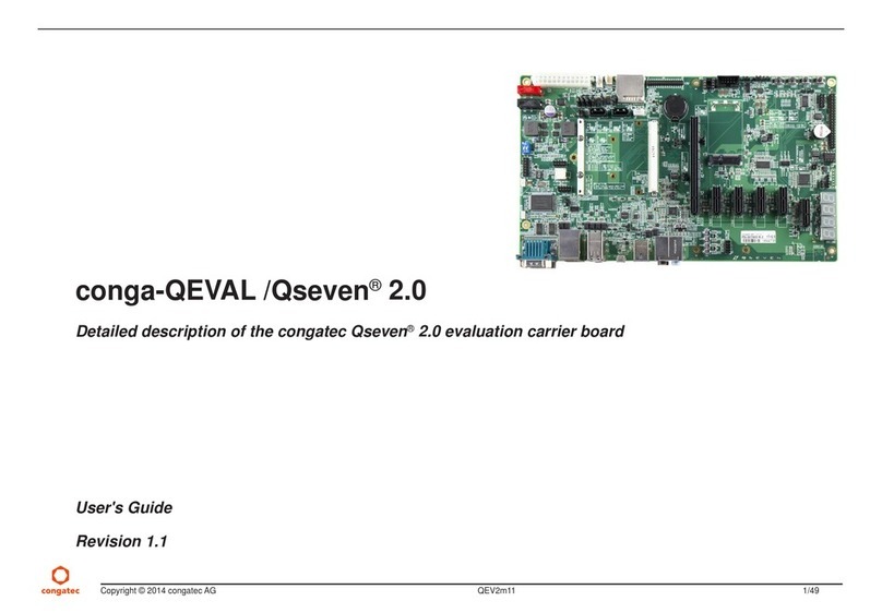
Congatec conga-QEVAL/Qseven 2.0 User manual

Congatec
Congatec COM Express conga-TCA5 User manual

Congatec
Congatec conga-QMX8-Plus User manual

Congatec
Congatec COM Express conga-TC370 User manual

Congatec
Congatec COM Express conga-TCA7 User manual

Congatec
Congatec COM Express conga-B915 User manual

Congatec
Congatec conga-QA3 User manual

Congatec
Congatec conga-MA7 User manual

Congatec
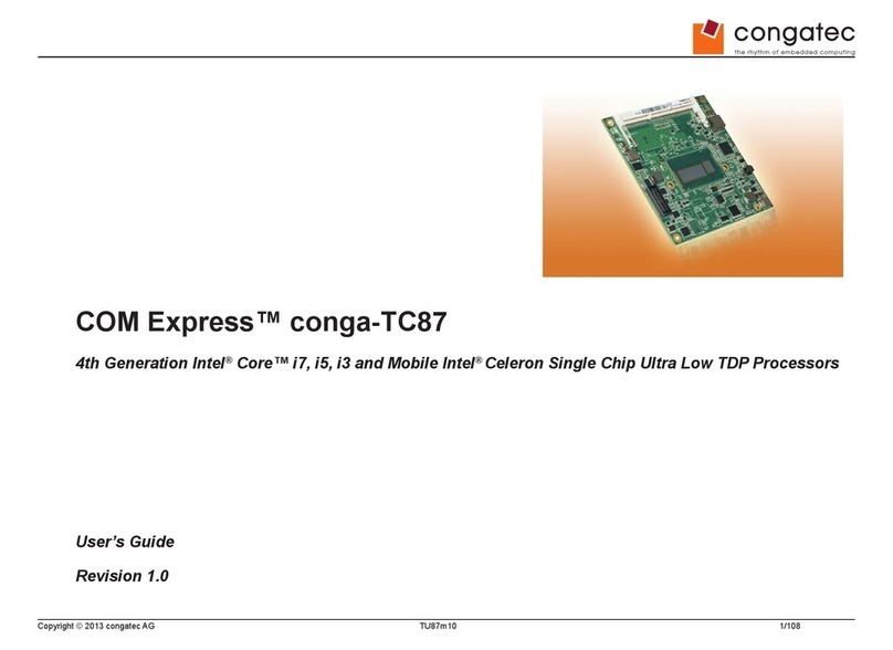
Congatec COM Express conga-TC87 User manual