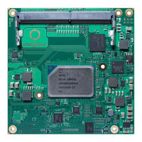
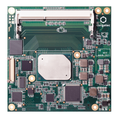
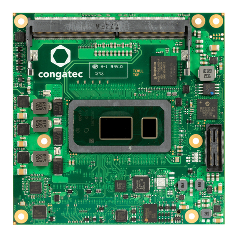
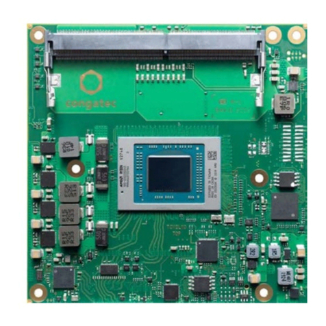
Congatec COM Express conga-B915 User manual

COM Express™ conga-B915
Intel®Celeron M processors with an Intel®910GMLE or 915GME chipset
User’s Guide
Revision 1.0

Copyright © 2008 congatec AG B915m10 2/92
Revision History
Revision Date (dd.mm.yy) Author Changes
0.1 04.04.08 GDA Preliminary release
1.0 02.03.10 GDA Ofcial release. Corrected section 4.1.11 ‘Power Control’ by changing SUS_S5#/PS_ON to SUS_S3#/PS_ON. Corrected SUS_S3# and SUS_S5#
pin descriptions in Table 15 ‘Power and System Management Signal Descriptions’. Added pin numbers to sections 7, “Signal Descriptions and
Pinout Tables.” Updated section 9 “BIOS Setup Description”.

Copyright © 2008 congatec AG B915m10 3/92
Preface
This user’s guide provides information about the components, features, connectors and BIOS Setup menus available on the conga-B915. It is
one of three documents that should be referred to when designing a COM Express™ application. The other reference documents that should
be used include the following:
COM Express™ Design Guide
COM Express™ Specication
The links to these documents can be found on the congatec AG website at www.congatec.com
Disclaimer
The information contained within this user’s guide, including but not limited to any product specication, is subject to change without notice.
congatec AG provides no warranty with regard to this user’s guide or any other information contained herein and hereby expressly disclaims
any implied warranties of merchantability or tness for any particular purpose with regard to any of the foregoing. congatec AG assumes
no liability for any damages incurred directly or indirectly from any technical or typographical errors or omissions contained herein or for
discrepancies between the product and the user’s guide. In no event shall congatec AG be liable for any incidental, consequential, special, or
exemplary damages, whether based on tort, contract or otherwise, arising out of or in connection with this user’s guide or any other information
contained herein or the use thereof.
Intended Audience
This user’s guide is intended for technically qualied personnel. It is not intended for general audiences.

Copyright © 2008 congatec AG B915m10 4/92
Symbols
The following symbols are used in this user’s guide:
Warning
Warnings indicate conditions that, if not observed, can cause personal injury.
Caution
Cautions warn the user about how to prevent damage to hardware or loss of data.
Note
Notes call attention to important information that should be observed.
Terminology
Term Description
GB Gigabyte (1,073,741,824 bytes)
GHz Gigahertz (one billion hertz)
kB Kilobyte (1024 bytes)
MB Megabyte (1,048,576 bytes)
Mbit Megabit (1,048,576 bits)
kHz Kilohertz (one thousand hertz)
MHz Megahertz (one million hertz)
TDP Thermal Design Power
PCIe PCI Express
SATA Serial ATA
PATA Parallel ATA
T.O.M. Top of memory = max. DRAM installed
HDA High Denition Audio
I/F Interface
N.C. Not connected
N.A. Not available
TBD To be determined

Copyright © 2008 congatec AG B915m10 5/92
Copyright Notice
Copyright © 2008, congatec AG. All rights reserved. All text, pictures and graphics are protected by copyrights. No copying is permitted without
written permission from congatec AG.
Some of the information found in this user’s guide has been extracted WITH EXPRESS PERMISSION from the following COPYRIGHTED
American Megatrends, Inc documents:
AMIBIOS8_HDD_Security.pdf•
AMIBIOS8-Flash-Recovery-Whitepaper.pdf•
AMIBIOS8_SerialRedirection.pdf•
AMIBIOS8 Setup User’s Guide•
The above mentioned documents are Copyright© 2005 American Megatrends, Inc. All rights reserved. All text, pictures and graphics are
protected by copyrights. No copying is permitted without written permission from American Megatrends, Inc.
congatec AG has made every attempt to ensure that the information in this document is accurate yet the information contained within is
supplied “as-is”.
Trademarks
Intel and Pentium are registered trademarks of Intel Corporation. Expresscard is a registered trademark of Personal Computer Memory
Card International Association (PCMCIA). COM Express™ is a registered trademark of PCI Industrial Computer Manufacturers Group. PCI
Express is a registered trademark of Peripheral Component Interconnect Special Interest Group (PCI-SIG). I²C is a registered trademark of
Philips Corporation. CompactFlash is a registered trademark of CompactFlash Association. Winbond is a registered trademark of Winbond
Electronics Corp. AVR is a registered trademark of Atmel Corporation. ETX is a registered trademark of Kontron AG. AMICORE8 is a registered
trademark of American Megatrends Inc. Microsoft®, Windows®, Windows CE®, Windows XP® and Windows Vista® are registered trademarks of
Microsoft Corporation. VxWorks is a registered trademark of WindRiver. conga, congatec and XTX are registered trademark of congatec AG.
All product names and logos are property of their owners.

Copyright © 2008 congatec AG B915m10 6/92
Warranty
congatec AG makes no representation, warranty or guaranty, express or implied regarding the products except its standard form of limited
warranty (“Limited Warranty”). congatec AG may in its sole discretion modify its Limited Warranty at any time and from time to time.
Beginning on the date of shipment to its direct customer and continuing for the published warranty period, congatec AG represents that the
products are new and warrants that each product failing to function properly under normal use, due to a defect in materials or workmanship or
due to non conformance to the agreed upon specications, will be repaired or exchanged, at congatec AG’s option and expense.
Customer will obtain a Return Material Authorization (“RMA”) number from congatec AG prior to returning the non conforming product freight
prepaid. congatec AG will pay for transporting the repaired or exchanged product to the customer.
Repaired, replaced or exchanged product will be warranted for the repair warranty period in effect as of the date the repaired, exchanged or
replaced product is shipped by congatec AG, or the remainder of the original warranty, whichever is longer. This Limited Warranty extends to
congatec AG’s direct customer only and is not assignable or transferable.
Except as set forth in writing in the Limited Warranty, congatec AG makes no performance representations, warranties, or guarantees, either
express or implied, oral or written, with respect to the products, including without limitation any implied warranty (a) of merchantability, (b) of
tness for a particular purpose, or (c) arising from course of performance, course of dealing, or usage of trade.
congatec AG shall in no event be liable to the end user for collateral or consequential damages of any kind. congatec AG shall not otherwise
be liable for loss, damage or expense directly or indirectly arising from the use of the product or from any other cause. The sole and exclusive
remedy against congatec AG, whether a claim sound in contract, warranty, tort or any other legal theory, shall be repair or replacement of the
product only.
COM Express™ Concept
COM Express™ is an open industry standard dened specically for COMs (computer on modules). It’s creation provides the ability to make a
smooth transition from legacy parallel interfaces to the newest technologies based on serial buses available today. COM Express™ modules
are available in following form factors:
• Compact 95mm x 95mm
• Basic 125mm x 95mm
• Extended 155mm x 110mm

Copyright © 2008 congatec AG B915m10 7/92
The COM Express™ specication 1.0 denes ve different pinout types.
Types Connector Rows PCI Express Lanes PCI IDE Channels LAN ports
Type 1 A-B Up to 6 1
Type 2 A-B C-D Up to 22 32 bit 1 1
Type 3 A-B C-D Up to 22 32 bit 3
Type 4 A-B C-D Up to 32 1 1
Type 5 A-B C-D Up to 32 3
congatec AG modules utilize the Type 2 pinout denition. They are equipped with two high performance connectors that ensure stable data
throughput.
The COM (computer on module) integrates all the core components and is mounted onto an application specic carrier board. COM modules
are a legacy-free design (no Super I/O, PS/2 keyboard and mouse) and provide most of the functional requirements for any application. These
functions include, but are not limited to, a rich complement of contemporary high bandwidth serial interfaces such as PCI Express, Serial ATA,
USB 2.0, and Gigabit Ethernet. The Type 2 pinout provides the ability to offer 32-bit PCI, Parallel ATA, and LPC options thereby expanding
the range of potential peripherals. The robust thermal and mechanical concept, combined with extended power-management capabilities, is
perfectly suited for all applications.
Carrier board designers can utilize as little or as many of the I/O interfaces as deemed necessary. The carrier board can therefore provide all
the interface connectors required to attach the system to the application specic peripherals. This versatility allows the designer to create a
dense and optimized package, which results in a more reliable product while simplifying system integration. Most importantly, COM Express™
modules are scalable, which means once an application has been created there is the ability to diversify the product range through the use of
different performance class or form factor size modules. Simply unplug one module and replace it with another, no redesign is necessary.
Certication
congatec AG is certied to DIN EN ISO 9001:2000 standard.
Technical Support
congatec AG technicians and engineers are committed to providing the best possible technical support for our customers so that our products
can be easily used and implemented. We request that you rst visit our website at www.congatec.com for the latest documentation, utilities and
drivers, which have been made available to assist you. If you still require assistance after visiting our website then contact our technical support
department by email at [email protected]

Copyright © 2008 congatec AG B915m10 8/92
Lead-Free Designs (RoHS)
All congatec AG designs are created from lead-free components and are completely RoHS compliant.
Electrostatic Sensitive Device
All congatec AG products are electrostatic sensitive devices and are packaged accordingly. Do not open or handle a congatec AG product
except at an electrostatic-free workstation. Additionally, do not ship or store congatec AG products near strong electrostatic, electromagnetic,
magnetic, or radioactive elds unless the device is contained within its original manufacturer’s packaging. Be aware that failure to comply with
these guidelines will void the congatec AG Limited Warranty.
conga-B915 Options Information
The conga-B915 is currently available in three different standard variants that feature the Intel® 82910GMLE chipset. This user’s guide describes
all of these options. Below you will nd an order table showing the different congurations that are currently offered by congatec AG. Check the
table for the Part no./Order no. that applies to your product. This will tell you what options described in this user’s guide are available on your
particular module.
Part-No. 057741 077587 025540
Processsor Intel® Celeron M 600MHz
ULV (Ultra Low Voltage)
Intel® Celeron M 373 1.0GHz
ULV (Ultra Low Voltage)
Intel® Celeron M 370
1.5GHz
Chipset 82910GMLE 82910GMLE 82910GMLE
L2 Cache 512 kByte 512 kByte 1 MByte
FSB 400MHz 400MHz 400MHz
CPU TDP 7 W 5 W 21 W
Note
For completeness this user’s guide describes the features found on conga-B915 modules that are equipped with either the Intel®82910GMLE
or 82915GME chipset. For information about pricing and availability of conga-B915 modules that feature the Intel®82915GME chipset, contact
your local congatec sales representative.

Copyright © 2008 congatec AG B915m10 9/92
Contents
1 Specications........................................................................... 12
1.1 Feature List.............................................................................. 12
1.2 Supported Operating Systems................................................. 13
1.3 Mechanical Dimensions........................................................... 13
1.4 Supply Voltage Standard Power .............................................. 14
1.4.1 Electrical Characteristics.......................................................... 14
1.4.2 Rise Time................................................................................. 14
1.5 Power Consumption................................................................. 15
1.5.1 Intel® Celeron M 600MHz 512k L2 cache ............................... 16
1.5.2 Intel® Celeron M 1.0GHz 512k L2 cache ................................. 17
1.5.3 Intel® Celeron M 1.5GHz 1MB L2 cache.................................. 17
1.6 Supply Voltage Battery Power ................................................. 17
1.6.1 CMOS Battery Power Consumption ........................................ 18
1.7 Environmental Specications................................................... 18
2 Block Diagram.......................................................................... 19
3 Heatspreader ........................................................................... 20
3.1 Heatspreader Dimensions ....................................................... 21
4 Connector Subsystems Rows A, B, C, D................................. 22
4.1 Primary Connector Rows A and B............................................ 23
4.1.1 Serial ATA™ (SATA)................................................................. 23
4.1.2 USB 2.0.................................................................................... 23
4.1.3 AC’97 Digital Audio Interface/HDA........................................... 23
4.1.4 Gigabit Ethernet ...................................................................... 23
4.1.5 LPC Bus................................................................................... 24
4.1.6 I²C Bus 400kHz........................................................................ 24
4.1.7 PCI Express™ ......................................................................... 24
4.1.8 ExpressCard™......................................................................... 24
4.1.9 Graphics Output (VGA/CRT) ................................................... 24
4.1.10 LCD.......................................................................................... 24
4.1.11 Power Control .......................................................................... 25
4.1.12 Power Management................................................................. 26
4.2 Secondary Connector Rows C and D...................................... 26
4.2.1 PCI Express Graphics (PEG)................................................... 26
4.2.2 SDVO....................................................................................... 26
4.2.3 PCI Bus.................................................................................... 26
4.2.4 IDE (PATA) ............................................................................... 26
5 Additional Features .................................................................. 27
5.1 Watchdog................................................................................. 27
5.2 Onboard Microcontroller .......................................................... 27
5.3 Embedded BIOS...................................................................... 27
5.3.1 Simplied Overview of BIOS Setup Data Backup.................... 28
5.4 Security Features..................................................................... 29
5.5 Suspend to Ram ...................................................................... 29
5.6 congatec Battery Management Interface................................. 29
6 conga Tech Notes .................................................................... 30
6.1 Comparison of I/O APIC to 8259 PIC Interrupt mode .............. 30
6.2 Native vs. Compatible IDE mode............................................. 30
6.2.1 Compatible Mode..................................................................... 30
6.2.2 Native ...................................................................................... 30
6.3 Intel® Processor Features ........................................................ 31
6.3.1 Thermal Monitor and Catastrophic Thermal Protection ........... 31
6.3.2 Processor Performance Control............................................... 32
6.4 Thermal Management.............................................................. 33
6.5 ACPI Suspend Modes and Resume Events ............................ 34
6.6 USB 2.0 EHCI Host Controller Support ................................... 36
7 Signal Descriptions and Pinout Tables..................................... 37
7.1 A-B Connector Signal Descriptions.......................................... 38
7.2 A-B Connector Pinout .............................................................. 45
7.3 C-D Connector Signal Descriptions ......................................... 47
7.4 C-D Connector Pinout.............................................................. 53
7.5 Boot Strap Signals ................................................................... 55
8 System Resources................................................................... 56
8.1 System Memory Map............................................................... 56
8.2 I/O Address Assignment........................................................... 57
8.2.1 LPC Bus................................................................................... 58
Copyright © 2008 congatec AG B915m10 10/92
8.3 Interrupt Request (IRQ) Lines.................................................. 59
8.4 PCI Conguration Space Map ................................................. 61
8.5 PCI Interrupt Routing Map ....................................................... 62
8.6 PCI Bus Masters...................................................................... 63
8.7 I²C Bus..................................................................................... 63
8.8 SM Bus .................................................................................... 63
9 BIOS Setup Description ........................................................... 64
9.1 Entering the BIOS Setup Program........................................... 64
9.1.1 Boot Selection Popup .............................................................. 64
9.1.2 Manufacturer Default Settings ................................................. 64
9.2 Setup Menu and Navigation..................................................... 64
9.3 Main Setup Screen .................................................................. 65
9.4 Advanced Setup....................................................................... 66
9.4.1 ACPI Conguration Submenu.................................................. 67
9.4.2 PCI Conguration Submenu .................................................... 69
9.4.2.1 PCI IRQ Resource Exclusion Submenu .................................. 69
9.4.2.2 PCI Interrupt Routing Submenu............................................... 69
9.4.3 Graphics Conguration Submenu............................................ 70
9.4.4 CPU Conguration Submenu................................................... 73
9.4.5 Chipset Conguration Submenu.............................................. 74
9.4.6 I/O Interface Conguration Submenu ...................................... 75
9.4.6.1 SIO Winbond W83627 Conguration....................................... 75
9.4.6.2 SIO SMSC SCH3114 Conguration......................................... 76
9.4.7 Clock Conguration.................................................................. 76
9.4.8 IDE Conguration Submenu .................................................... 77
9.4.8.1 Primary/Secondary IDE Master/Slave Submenu ..................... 78
9.4.9 USB Conguration Submenu................................................... 79
9.4.9.1 USB Mass Storage Device Conguration Submenu................ 80
9.4.10 Keyboard/Mouse Conguration Submenu ............................... 80
9.4.11 Remote Access Conguration Submenu ................................. 81
9.4.12 Hardware Monitoring Submenu ............................................... 82
9.4.13 Watchdog Conguration Submenu .......................................... 83
9.5 Boot Setup ............................................................................... 84
9.5.1 Boot Device Priority ................................................................. 84
9.5.2 Boot Settings Conguration ..................................................... 85
9.6 Security Setup.......................................................................... 86
9.6.1 Security Settings...................................................................... 86
9.6.2 Hard Disk Security ................................................................... 87
9.6.2.1 Hard Disk Security User Password.......................................... 87
9.6.2.2 Hard Disk Security Master Password ...................................... 87
9.7 Power Setup ............................................................................ 88
9.7.1 Exit Menu................................................................................. 88
10 Additional BIOS Features ........................................................ 89
10.1 Updating the BIOS................................................................... 89
10.2 BIOS Recovery ........................................................................ 89
10.2.1 BIOS Recovery via Storage Devices ....................................... 89
10.2.2 BIOS Recovery via Serial Port................................................. 90
10.3 Serial Port and Console Redirection........................................ 90
10.4 BIOS Security Features ........................................................... 90
10.5 Hard Disk Security Features.................................................... 91
11 Industry Specications ............................................................. 92

Copyright © 2008 congatec AG B915m10 11/92
List of Tables
Table 1 Feature Summary .................................................................... 12
Table 2 Signal Tables Terminology Descriptions .................................. 37
Table 3 AC’97/Intel® High Denition Audio Link Signals Descriptions .. 38
Table 4 Gigabit Ethernet Signal Descriptions ....................................... 39
Table 5 Serial ATA Signal Descriptions ................................................. 39
Table 6 PCI Express Signal Descriptions (general purpose)................ 40
Table 7 ExpressCard Support Pins Descriptions.................................. 40
Table 8 LPC Signal Descriptions .......................................................... 41
Table 9 USB Signal Descriptions.......................................................... 41
Table 10 CRT Signal Descriptions .......................................................... 42
Table 11 LVDS Signal Descriptions ........................................................ 42
Table 12 TV-Out Signal Descriptions...................................................... 43
Table 13 Miscellaneous Signal Descriptions .......................................... 43
Table 14 General Purpose I/O Signal Descriptions ................................ 44
Table 15 Power and System Management Signal Descriptions ............. 44
Table 16 Power and GND Signal Descriptions ....................................... 45
Table 17 Connector A-B Pinout .............................................................. 45
Table 18 PCI Signal Descriptions ........................................................... 47
Table 19 IDE Signal Descriptions ........................................................... 48
Table 20 PCI Express Signal Descriptions (x16 Graphics)..................... 49
Table 21 SDVO Signal Descriptions ....................................................... 51
Table 22 Module Type Denition Signal Description .............................. 52
Table 23 Power and GND Signal Descriptions ....................................... 52
Table 24 Miscellaneous Signal Descriptions .......................................... 52
Table 25 Connector C-D Pinout.............................................................. 53
Table 26 Boot Strap Signal Descriptions ................................................ 55
Table 27 Memory Map ............................................................................ 56
Table 28 I/O Address Assignment........................................................... 57
Table 29 IRQ Lines in PIC mode ............................................................ 59
Table 30 IRQ Lines in APIC mode .......................................................... 60
Table 31 PCI Conguration Space Map ................................................. 61
Table 32 PCI Interrupt Routing Map ....................................................... 62
Table 33 PCI Interrupt Routing Map (continued) .................................... 62

Copyright © 2008 congatec AG B915m10 12/92
Specications1
Feature List1.1
Table 1 Feature Summary
Form Factor Based on COM Express™ standard pinout Type 2 (Basic size 95 x 125mm)
Processor Intel® Celeron M 600MHz with 512 kB L2 cache ULV (Ultra Low Voltage)
Intel® Celeron M 373 ULV 1.0GHz, with 512 kB L2 cache (Ultra Low Voltage)
Intel® Celeron M 370 1.5GHz, with 1 MB L2 cache
Memory 1 socket: SO-DIMM DDR2 up to 2 GB physical memory.
Chipset Graphics and Memory Controller Hub (GMCH) Intel® 82910GMLE or 82915GME
Intel®I/O Controller Hub 82801FBM (ICH6M)
Audio AC‘97 Rev.2.3 compatible, HDA (High Denition Audio)/digital audio interface with support for multiple codecs
Ethernet Gigabit Ethernet, Realtek RTL8111 (uses one x1 PCI Express Link)
Graphics Options Intel® Graphics Media Accelerator 900 with max.224MByte Dynamic Video Memory Technology (DVMT 3.0) as well as Dual independent display
support.
CRT Interface: 400 MHz RAMDAC•
Resolutions up to 2048x1536 @ 70Hz (QXGA)
Flat panel Interface (integrated) •
2x25-112MHz LVDS Transmitter
Supports all 1x18, 2x18, 1x24, 2x24 bit TFT congurations (current chipset
revisions support 24Bit modes although not ofcially stated by Intel®)
Supports both conventional (FPDI) and non-conventional (LDI) color mappings
Automatic Panel Detection via EPI (Embedded Panel Interface based on
VESA EDID™ 1.3) Resolutions 640x480 up to up to 1400x1050 (SXGA)
Up to 1600x1200 (UXGA) for 82915GME
Motion Video Support•
Up- and Downscaling
High denition content decode
H/W motion compensation
Subpicture support Dynamic bob and weave
AUX Output: 2 x Intel compliant SDVO ports (serial DVO) •
200MPixel/sec each (shared with PEG x16 pins on 82915GME
equipped variants) Supports external DVI, TV and LVDS
transmitter
Peripheral
Interfaces
2x Serial ATA• ®
3x x1 PCI Express• ® Links (optionally, one additional x1 link if x16 link
(available only on 82915GME equipped variants) is not used)
SDVO (the PCI Express Graphics x16 link available on 82915GME •
equipped variants is shared with SDVO)
8x USB 2.0 (EHCI)•
PCI Bus Rev. 2.3•
1x EIDE (UDMA-66/100)•
LPC Bus•
I²C Bus, Fast Mode (400 kHz) multimaster•
BIOS Based on AMIBIOS8® 1MByte Flash BIOS with congatec Embedded BIOS features
Power Management ACPI 2.0 compliant with battery support. Also supports Suspend to RAM (S3).
Note
Some of the features mentioned in the above Feature Summary are optional. Check the article number of your module and compare it to the
option information list on page 8 of this user’s guide to determine what options are available on your particular module.

Copyright © 2008 congatec AG B915m10 13/92
Supported Operating Systems1.2
The conga-B915 supports the following operating systems.
Microsoft• ® Windows® XP/2000
Microsoft• ® Windows® XP Embedded
Microsoft• ® Windows® CE 5.0 / 6.0
Linux•
QNX•
Mechanical Dimensions1.3
95.0 mm x 125.0 mm (3.74” x 4.92”)•
Height approximately 18 or 21mm (including heatspreader) depending on the carrier board connector that is used. If the 5mm (height) carrier •
board connector is used then approximate overall height is 18mm. If the 8mm (height) carrier board connector is used then approximate
overall height is 21mm.

Copyright © 2008 congatec AG B915m10 14/92
Supply Voltage Standard Power1.4
12V DC ± 5%•
The dynamic range shall not exceed the static range.
Electrical Characteristics1.4.1
Power supply pins on the module’s connectors limit the amount of input power. The following table provides an overview of the limitations for
pinout Type 2 (dual connector, 440 pins).
Power Rail Module Pin Current
Capability (Amps)
Nominal Input
(Volts)
Input Range
(Volts)
Derated Input
(Volts)
Max. Input Ripple
(10Hz to 20MHz)
(mV)
Max. Module Input Power
(w. derated input)
(Watts)
Assumed
Conversion
Efciency
Max. Load
Power
(Watts)
VCC_12V 16.5 12 11.4-12.6 11.4 +/- 100 188 85% 160
VCC_5V-SBY 2 5 4.75-5.25 4.75 +/- 50 9
VCC_RTC 0.5 3 2.0-3.3 +/- 20
Rise Time1.4.2
The input voltages shall rise from 10% of nominal to 90% of nominal at a minimum rise time of 250V/s. The smooth turn-on requires that, during
the 10% to 90% portion of the rise time, the slope of the turn-on waveform must be positive.
Nominal Static Range
Dynamic Range
Absolute Minimum
Absolute Maximum12.60V
11.40V
12V
12.10V
11.90V

Copyright © 2008 congatec AG B915m10 15/92
Power Consumption1.5
The power consumption values listed in this document were measured under a controlled environment. The hardware used includes a conga-B915
module, conga-CEVAL and conga-Cdebug carrier boards, CRT monitor, SATA drive, and USB keyboard. When using the conga-Cdebug, the
SATA drive was powered externally by an ATX power supply so that it does not inuence the power consumption value that is measured for
the module. The USB keyboard was detached once the module was congured within the OS. The module was rst inserted into the conga-
Cdebug, which was powered by a Direct Current (DC) power supply set to output 12V. The current consumption value displayed by the DC
power supply’s readout is the value that is recorded as the power consumption measurement for Desktop Idle, 100% Workload and Standby
modes. The power consumption of the conga-Cdebug (without module attached) was measured and this value was later subtracted from the
overall power consumption value measured when the module and all peripherals were connected. All recorded values are approximate.
The conga-Cdebug does not provide 5V Standby power therefore S3 mode was measured using the conga-CEVAL powered by an ATX power
supply with a multimeter attached to the 5V Standby power line. The 5V Standby power consumption of the conga-CEVAL (without module
attached) and all peripherals connected was rst measured and the resulting value was later subtracted from the overall S3 power consumption
value measured when the module was attached. All S3 recorded values are approximate.
Each module was measured while running Windows XP Professional with SP2 (service pack 2) and the “Power Scheme” was set to “Portable/
Laptop”. This setting ensures that Core 2 Duo and Core Duo processors run in LFM (lowest frequency mode) with minimal core voltage during
desktop idle. Celeron M processors do not support this feature and therefore always run at the same core voltage even during desktop idle.
Each module was tested while using a swissbit® DDR2 PC2-4200-444 512MB memory module. Using different sizes of RAM, as well as two
memory modules, will cause slight variances in the measured results.
Power consumption values were recorded during the following stages:
Windows XP Professional SP2
Desktop Idle•
100% CPU workload (see note below)•
Windows XP Professional Standby Mode (requires setup node “Suspend Mode” in the BIOS to be congured to S1 POS (Power On •
Suspend))
Suspend to RAM (requires setup node “Suspend Mode” in BIOS to be congured to S3 STR (suspend to RAM)). Supply power for S3 mode •
is 5V.
Note
A software tool was used to stress the CPU to 100% workload.

Copyright © 2008 congatec AG B915m10 16/92
Processor Information
In the following power tables there is some additional information about the processors. Intel® offers processors that are considered to be low
power consuming. These processors can be identied by their voltage status. Intel uses the following terms to describe these processors. If
none of these terms are used then the processor is not considered to be low power consuming.
LV=Low voltage
ULV=Ultra low voltage
When applicable, the above mentioned terms will be added to the power tables to describe the processor. For example:
Intel® Celeron M 1.0GHz 512k L2 cache
ULV
Intel® also describes the type of manufacturing process used for each processor. The following term is used:
nm=nanometer
The manufacturing process description is included in the power tables as well. See example below. For information about the manufacturing
process visit Intel®’s website.
Intel® Celeron M 1.0GHz 512k L2 cache
ULV 90nm
Intel1.5.1 ®Celeron M 600MHz 512k L2 cache
With 512MB memory installed
conga-B915 Art. No. 057741 Intel®Celeron M 600MHz 512k L2 cache
ULV 130nm
Layout Rev. B915LX0 /BIOS Rev. B915R004
Memory Size 512MB
Operating System Windows XP Professional SP2
Power State Desktop Idle 100% workload Standby Suspend to Ram (S3) 5V Input Power
Power consumption (measured in Amperes/Watts) 0.9 A/10.8 W (12V) 1.1 A/13.2 W (12V) 0.7 A/8.4 W (12V) 0.1 A/0.5 W (5V)

Copyright © 2008 congatec AG B915m10 17/92
Intel1.5.2 ®Celeron M 1.0GHz 512k L2 cache
With 512MB memory installed
conga-B915 Art. No. 077587 Intel®Celeron M 1.0GHz 512k L2 cache
ULV 90nm
Layout Rev. B915LX0 /BIOS Rev. B915R004
Memory Size 512MB
Operating System Windows XP Professional SP2
Power State Desktop Idle 100% workload Standby Suspend to Ram (S3) 5V Input Power
Power consumption (measured in Amperes/Watts) 0.8 A/9.6 W (12V) 1.2 A/14.4 W (12V) 0.8 A/9.6 W (12V) 0.1 A/0.5 W (5V)
Intel1.5.3 ®Celeron M 1.5GHz 1MB L2 cache
With 512MB memory installed
conga-B915 Art. No. 025540 Intel®Celeron M 1.5GHz 1MB L2 cache
90nm
Layout Rev. B915LX0 /BIOS Rev. B915R004
Memory Size 512MB
Operating System Windows XP Professional SP2
Power State Desktop Idle 100% workload Standby Suspend to Ram (S3) 5V Input Power
Power consumption (measured in Amperes/Watts) 1.0 A/12 W (12V) 2.1 A/25.2 W (12V) 1.2 A/14.4 W (12V) 0.1 A/0.5 W (5V)
Note
All recorded power consumption values are approximate and only valid for the controlled environment described earlier. 100% workload refers
to the CPU workload and not the maximum workload of the complete module. Supply power for S3 mode is 5V while all other measured modes
are supplied with 12V power. Power consumption results will vary depending on the workload of other components such as graphics engine,
memory, etc.
Supply Voltage Battery Power1.6
2.0V-3.6V DC•
Typical 3V DC•

Copyright © 2008 congatec AG B915m10 18/92
CMOS Battery Power Consumption1.6.1
RTC @ 20ºC Voltage Current
Integrated in the Intel®
I/O Controller Hub
82801FBM (ICH6M)
3V DC 2.49 µA
The CMOS battery power consumption value listed above should not be used to calculate CMOS battery lifetime. You should measure the
CMOS battery power consumption in your customer specic application in worst case conditions, for example during high temperature and
high battery voltage. The self-discharge of the battery must also be considered when determining CMOS battery lifetime. For more information
about calculating CMOS battery lifetime refer to application note AN9_RTC_Battery_Lifetime.pdf, which can be found on the congatec AG
website at www.congatec.com.
Environmental Specications1.7
Temperature Operation: 0° to 60°C Storage: -20° to +80°C
Humidity Operation: 10% to 90% Storage: 5% to 95%
Caution
The above operating temperatures must be strictly adhered to at all times. When using a heatspreader the maximum operating temperature
refers to any measurable spot on the heatspreader’s surface.
congatec AG strongly recommends that you use the appropriate congatec module heatspreader as a thermal interface between the module
and your application specic cooling solution.
If for some reason it is not possible to use the appropriate congatec module heatspreader, then it is the responsibility of the operator to ensure
that all components found on the module operate within the component manufacturer’s specied temperature range.
For more information about operating a congatec module without heatspreader contact congatec technical support.
Humidity specications are for non-condensing conditions.

Copyright © 2008 congatec AG B915m10 19/92
Block Diagram2
C-D
A-B
Realtek
Gigabit Ethernet
RTL8111B/C
Hardware
Monitor
Monitoring
Circuitry
ICH6M
Intel 82801FBM
RTC
Board Controller
Atmel
ATmega168
Watchdog
FWH
(BIOS)
TPM
(optional)
GMCH
Intel
®
82910GMLE
Intel
®
82915GME
CPU
Intel® Celeron M
DDR2-SODIMM
Socket
8x USB 2.0
CRT
LCD I/F
(LVDS)
AC’97 Digital Audio / HDA I/F
2x SATA
GPIs/GPOs
SPI
LPC Bus
PCI Bus
I2C
Fan
Control
Power Management and Control Signals
Gbit Ethernet
SM Bus
1x IDE
(Primary)
System Bus
(400MHz)
1x x1 PCIe Lane
3x x1 PCIe Lanes
DMI Interface
PCI Express Graphics x16
2x SDVO
x16
OR
4x x1 PCIe
Memory Bus
(400MHz)
PCI Express Graphics only
available on Intel®82915GME
equipped variants.
Note

Copyright © 2008 congatec AG B915m10 20/92
Heatspreader3
An important factor for each system integration is the thermal design. The heatspreader acts as a thermal coupling device to the module. It
is a 3mm thick aluminum plate.
The heatspreader is thermally coupled to the CPU via a thermal gap ller and on some modules it may also be thermally coupled to other heat
generating components with the use of additional thermal gap llers.
Although the heatspreader is the thermal interface where most of the heat generated by the module is dissipated, it is not to be considered
as a heatsink. It has been designed to be used as a thermal interface between the module and the application specic thermal solution. The
application specic thermal solution may use heatsinks with fans, and/or heat pipes, which can be attached to the heatspreader. Some thermal
solutions may also require that the heatspreader is attached directly to the systems chassis therefore using the whole chassis as a heat
dissipater.
Caution
There are 4 mounting holes on the heatspreader designed to attach the heatspreader to the module. These mounting holes must be used to
ensure that all components that are required to make contact with heatspreader do so. Failure to utilize the these mounting holes will result in
improper contact between these components and heatspreader thereby reducing heat dissipation efciency.
Attention must be given to the mounting solution used to mount the heatspreader and module into the system chassis. Do not use a threaded
heatspreader together with threaded carrier board standoffs. The combination of the two threads may be staggered, which could lead to
stripping or cross-threading of the threads in either the standoffs of the heatspreader or carrier board.
Table of contents
Other Congatec Computer Hardware manuals

Congatec
Congatec COM Express conga-TCV2 User manual

Congatec
Congatec conga-MA7 User manual

Congatec
Congatec Qseven conga-QMX6 User manual

Congatec
Congatec COM Express conga-TCA5 User manual

Congatec
Congatec COM Express conga-TC370 User manual

Congatec
Congatec COM Express conga-TC87 User manual

Congatec
Congatec COM Express conga-TCA7 User manual

Congatec
Congatec conga-QA3 User manual

Congatec
Congatec conga-QMX8-Plus User manual

Congatec
Congatec conga-QEVAL/Qseven 2.0 User manual