User Manual Page 5
4. Configuration of the CT 1000
4.1 Service Code
The service code is used for CM 1000's advanced settings such as changing the Master
Code and Service Code, LED indication and much more. The overview of the setting and
the factory settings can be seen in 4.2 Configuration Overview.
The service code is 12347890 (factory setting).
Note: Before the service code can be used the voltage must be turned OFF and ON
(the service code can now be entered within 10 seconds).
After entering the Service Code the reader is in programming mode (the green LED lit).
Each time a setting is made the CT 1000 goes back to the previous point and the next
setting can be made.
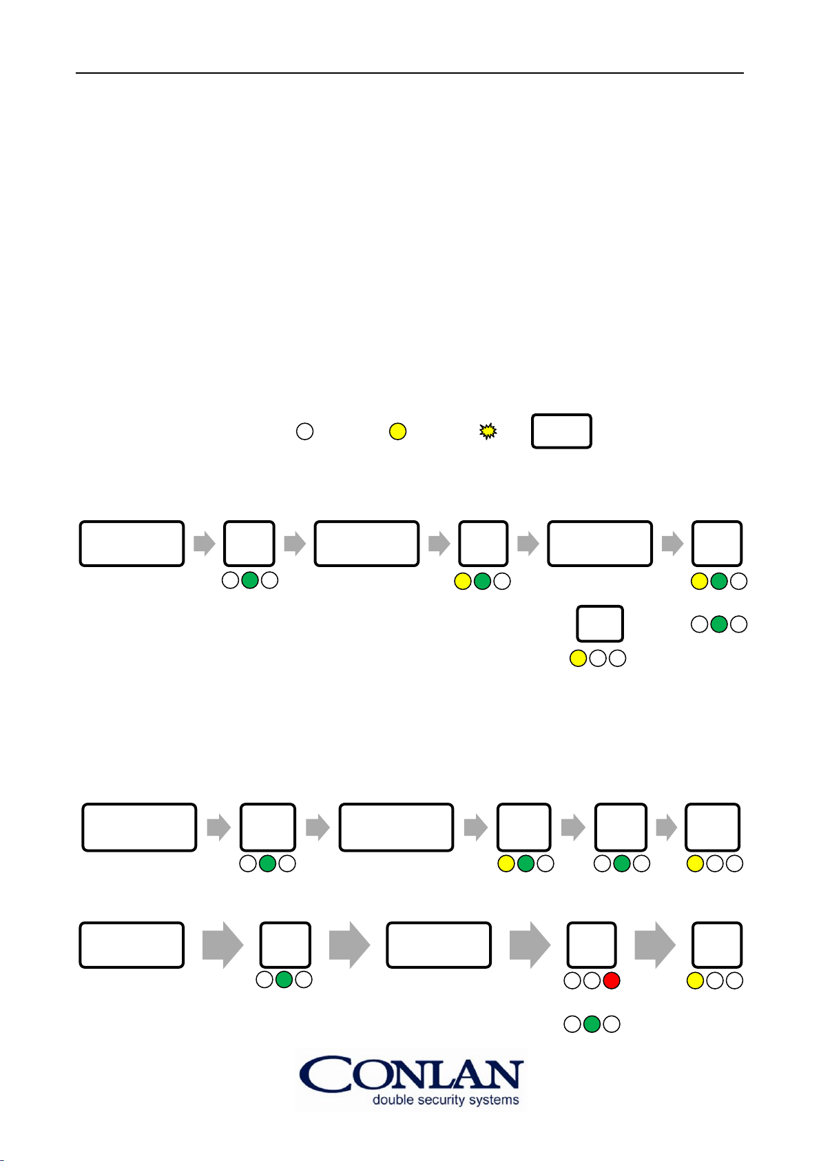
All parameters changes are made in the following format:
First enter the Service Code 12347890 within 10 seconds of power up, then #followed by
the parameter location 00 to 05 # New Value # #.
The Master Code and Service Code change sequence is shown in Full. Follow the same
sequence for all other parameters
4.2 Configuration Overview
Config. No.: Setting: Factory default:
00 Master Code (1 to 8 digits) 4711
01 Service Code (1 to 8 digits) 12347890
02 LED indication 31
03 Output time (white) 5
04 Output time (yellow) 5 (for codes)
05 Function settings 0
06 Activation with codes/bell 29
2500 All codes on the positions is deleted.
0250 Reset to factory default.
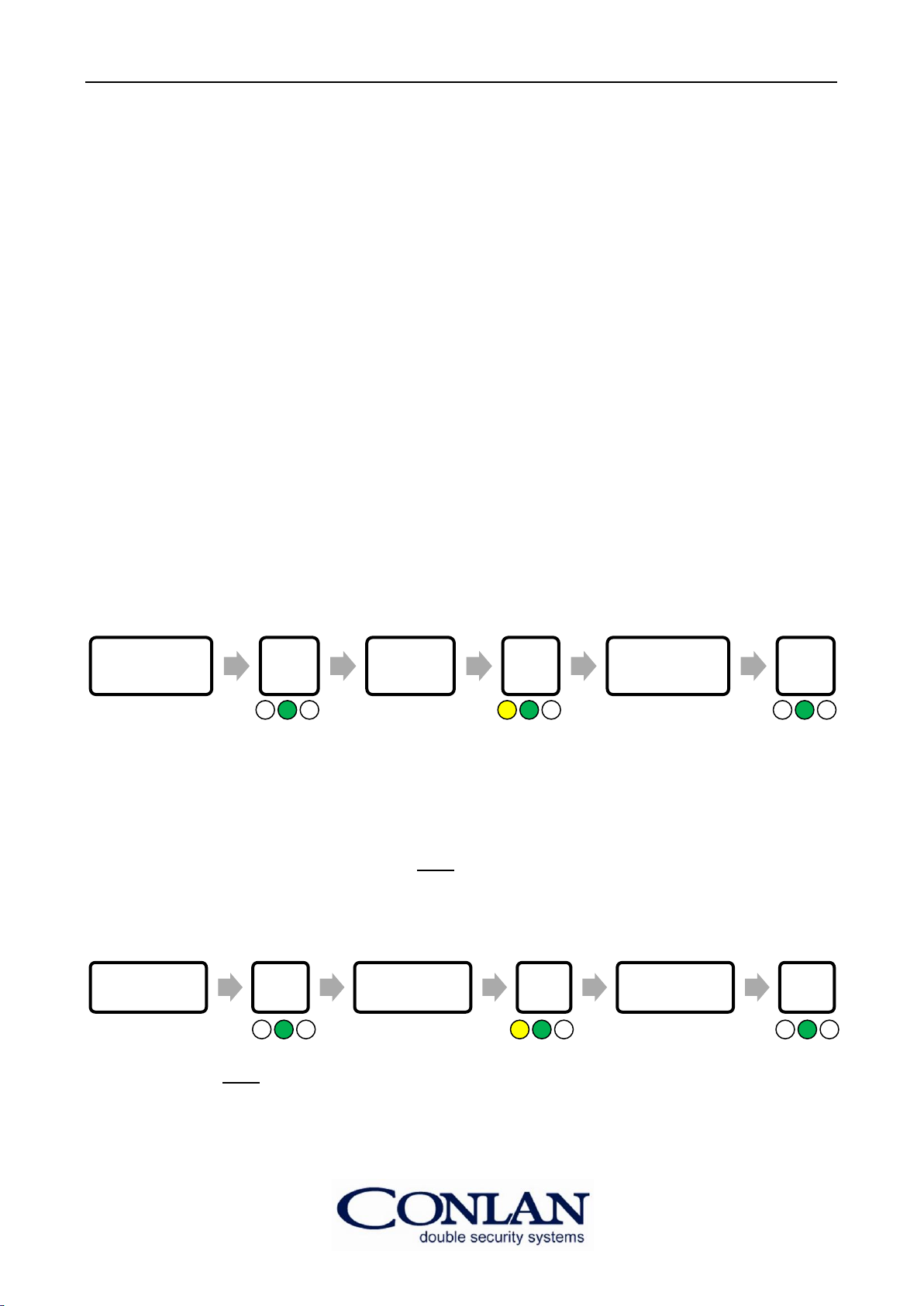
4.3 Changing the Master Code
By default is the Master Code 4711 and can only be used to program, change or delete
users on the CT 1000.
To change the Master Code, enter the following:
Key in the
Service Code # Key in
0 0 # Key in a new code #