manuals.online logo
Brands
  1. Home
  2. •
  3. Brands
  4. •
  5. Conotec
  6. •
  7. Temperature Controllers
  8. •
  9. Conotec FOX-23AF User manual

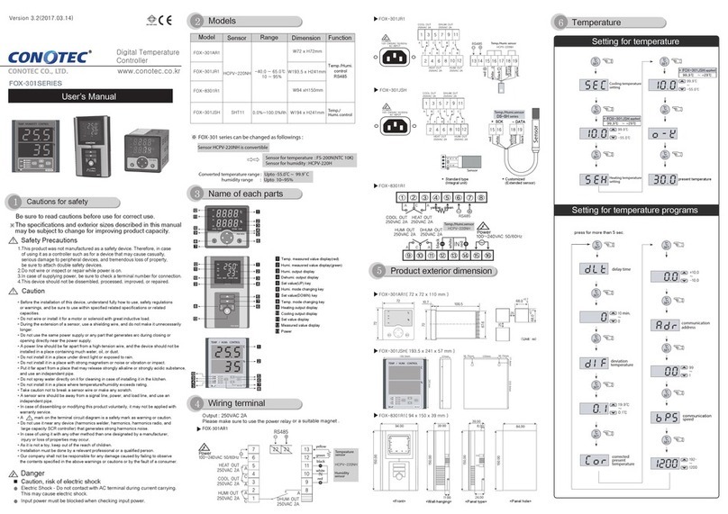
Conotec FOX-23AF User manual

Caution for safety
Read carefully this instruction manual before use and use
the product properly.
The specifications, appearance and dimension may be changed
for improvement of performance without a prior notice.
1. This product is not made as a safety device, so when it is used for
a control of devices feared to cause casualties, damages to the
peripheral devices or huge property loss, the double safety
devices should be arranged before use.
2. Avoid connecting lines, checking and repairing the products while
power is supplied.
3. Connect power after making sure the terminal number.
4. Never disassemble modify, improve or repair the product.
CAUTIONS
Be well-informed of how to use, safety regulations, warnings, etc
before installation of this device and apply it to the extent of the defined
specifications and relevant capacity without fail.
Avoid wiring or installation to a motor or solenoid with a large inductive load.
Use a shiled cable for extention of the sensor and ensure not to make it longer
than the necessity.
Ensure not to use the parts generating arc when switching at the same power
source or near to it.
Keep the po wer cable away from a high-tention po
w er line and ensure not to
install it at a place with serious oil and dirt.
Avoid strong magnetic field or serious noise, vibration or impact.
Keep away from the place where strong alkaline or acid material is directly
released and use an independent pipe line.
When it is installed at kitchen, ensure not to pour water directly over the product
Keep the sensor cable away from signal line, po w er source, po wer line or
loaded line and use an independent pipe line.
Note that the mark of in terminal connection diagram is the safety
expression for warnings or cautions.
Avoid using the product close to the device generating noises(high frequency
welder, high frequency sewing machine, high frequency radio, large capacity
SCR Controller, etc).
The use in any way other than what is instructed by the manufacturer may
cause injury or property loss.
It is not a toy and keep it out of reach of children’s hand.
The installation of the device should be performed by an expert or a qualified
personnel without fail.
We shall not take any responsibility for the damage caused by non-compliance
with the abo ve-mentioned warnings or cautions or by any consumer’s mistake.
for cleaning.
Operating Manual
Electric shock -Do not touch AC terminal during application of
electric current. It may cause electric shock.
Cut the power supply without fail during checking the input power.
Controlled output
Sensor
Model
Temperature
Functions
range
Cooler only
Relay contact
control
Defrost control
control
Cooler only
2003S
(5A)
control
Defrost control
control
Relay contact
OUTPUT DISPLAY
DEFROST OUTPUT DISPLAY
OUTPUT DISPLAY
DEFROST SWITCH
UP SWITCH
FUNCTION CHANGE
DOWN SWITCH
User’s mode changing(Temperature setting)
How to change the setting temp. for Main output
If press it once, the setting value is flickered.
or the value can be UP & DOWN with this key.
Mode setting for user
A key to enter to installer mode if press for more than
5 sec. change with these keys.
DEFROST
Output
Output
Please make use of the power relay or
magnet surely.
Example for connection of relay
machine(load)
Note that use of load exceeding capacity of
contact may cause fusion of contact,
poor contact, damage of relay, etc.
power
Relay contact
output terminal
present temperature
Change the set value by pressing
these keys.
Flickering
the set temp.
Changing
the set
temperature
After changing the set value
press this key.
Confirm the
setting of
letter OK
Present
temperature
Displays the confirmed letter(OK)for
saving set value,
and displayed the present temperature.
By pressing this key, set value is
flickered
Press for more than 5 seconds.
setting the
display unit
Setting OFF time
for defrost
Setting ON time
for defrost
output
delay time
FAN setting
Chart
FAN ON
min,sec
Defrost
F
A
N
How to set manual defrost
Detailed manual
: Setting for temperature deviation
- In the ON/OFF control, it needs at regular interval between ON and OFF.
- By operating the ON/OFF control frequently, the relay or its output
contact can be damaged quickly and it also occurs the hunting
(oscillating, chattering) by virtue of external noise. You can make use of
the temperature deviation in order to protect its relay or contact and
Method of temp. deviation when ON/OFF control
present temp.
setting temp.
temp. deviation
output
output
setting temp.
present temp.


>+
󰄭
setting
so on.
: Delay time of the output
In case of operating the ON/OFF control very often.
(Cooler, compressor, etc)
To protect the operation machinery when re-input of the power
supply or momentary stoppage of power supply.
󰄖
󰄖
: 25.0℃,
: 1.30,
: 1.0℃
set value
set temp.
set value
when the output is ON in that case?

point while at the present
temperature
The reason why the output delay time applied
not
, but from start , is due to

)
ex
time after 1 min 30sec.
increase, setting
(deviation)
ex)real temp.
display
Correction of the present temperature.
correction
display
The product itself has no problem, but the correction function
for that if temp. differs between an error occurs in the input
from outside and basic temp. (ex. mercury thermometer or an
existed using thermometer, temperature controller)
(corrected present temperature)
Defrost OFF time
- Setting range
- At the cycle of defrost, starts to defrost
:
:
Defrost ON time
- Setting range
- Defrosting during defrost time,
(4 hours)
if setting
:
ex)
Defrost OFF time
defrost time
Defrost OFF time
Every 4 hours, 10 minutes defrost operation is repeated.
(4 hours)
(10 min)
(4 hours)
Fan setting refer to the flow chart of program setting
After defrost, FAN ON delay time
Setting range (min, sec)
-
ex sec
after defrost
Comp. delay time
1 minute applied
output waiting
defrost completed
output
sec
FAN output
Range
sensor sensor sensor sensor sensor
Cooler
FAN
output
After defrost
COMP delay time
time time
time
defrost OFF
defrost
defrost OFF
FAN setting
FAN output ON
defrost : FAN output OFF
defrost
output
defrost
Main output
setting
Defrost setting
defrost OFF time
hrs
min
defrost time
<temp. setting> (refer to the temp.setting mode)
<program setting>(refer to the program setting mode)
(one-side deviation, setting point OFF)
(due to the interval of ON/OFF 2.0 C)
1. Cooling drive
- OFF setting : If temperature below 0.0 C
- ON setting : If temperature above 5.0 C
2. Defrost output : Every 10 minutes ON for 4 hours.
3. FAN output
- ON setting : If COMP output ON
- OFF setting :
If COMP output OFF and defrost ON
How to set the set value of temperature contoller
as the above conditions?
※ Above product ’s information can be changed to improve its quality without any notification.
When using this product, please observe the information of caution & warning due to give rise to disordering.
This device is suitable for following environment.
Surrounding temp.: 0~ 60
Surrounding humi.: Less than 80%Rh
Rated volt.: 220VAC ±10% 50/60Hz

This manual suits for next models

1

Other Conotec Temperature Controllers manuals

Conotec FOX-301 Series User manual

Conotec

Conotec FOX-301 Series User manual

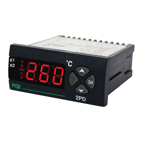
Conotec FOX-2PD User manual

Conotec

Conotec FOX-2PD User manual

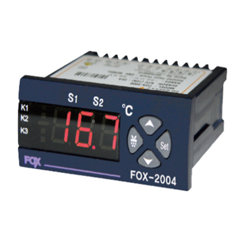
Conotec FOX-2004 User manual

Conotec

Conotec FOX-2004 User manual

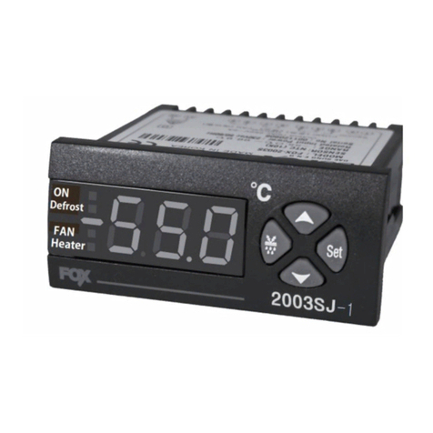
Conotec FOX-2003SJ-1 User manual

Conotec

Conotec FOX-2003SJ-1 User manual

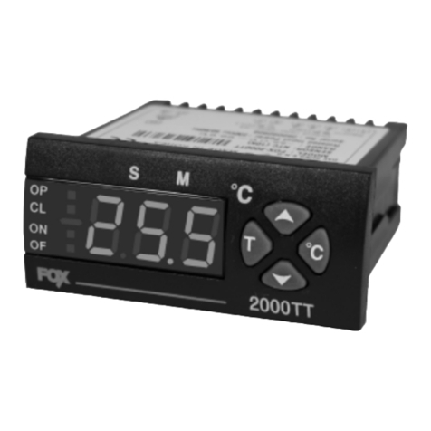
Conotec FOX-2000TT User manual

Conotec

Conotec FOX-2000TT User manual

Popular Temperature Controllers manuals by other brands

Resol DeltaSol BS/4 quick guide

Resol

Resol DeltaSol BS/4 quick guide

Poniie TC-10A user manual

Poniie

Poniie TC-10A user manual

Jaga BRIZA 12 manual

Jaga

Jaga BRIZA 12 manual

J-KEM Scientific Gemini user manual

J-KEM Scientific

J-KEM Scientific Gemini user manual

Delta Electronics DTD4848 Specifications

Delta Electronics

Delta Electronics DTD4848 Specifications

Penn A421ABT series installation instructions

Penn

Penn A421ABT series installation instructions

dixell XT110C Installation and operating instructions

dixell

dixell XT110C Installation and operating instructions

Walton C Series user manual

Walton

Walton C Series user manual

Trane ZSENS930AW00MA Installer's guide

Trane

Trane ZSENS930AW00MA Installer's guide

Store It Cold CoolBot Quick start setup guide

Store It Cold

Store It Cold CoolBot Quick start setup guide

Siemens HZ39050 instruction manual

Siemens

Siemens HZ39050 instruction manual

S+S Regeltechnik THERMASGARD RGTF1 Series Operating Instructions, Mounting & Installation

S+S Regeltechnik

S+S Regeltechnik THERMASGARD RGTF1 Series Operating Instructions, Mounting & Installation

Leister CSS operating instructions

Leister

Leister CSS operating instructions

Honeywell C7772 Series Product data

Honeywell

Honeywell C7772 Series Product data

PRG SmartXcan quick start guide

PRG

PRG SmartXcan quick start guide

Omron E5CN-HT user manual

Omron

Omron E5CN-HT user manual

La Crosse Technology TX21U instruction manual

La Crosse Technology

La Crosse Technology TX21U instruction manual

Flexit EcoNordic WH4 Assembly instructions

Flexit

Flexit EcoNordic WH4 Assembly instructions

manuals.online logo
manuals.online logoBrands
  • About & Mission
  • Contact us
  • Privacy Policy
  • Terms and Conditions

Copyright 2025 Manuals.Online. All Rights Reserved.