manuals.online logo
Brands
  1. Home
  2. •
  3. Brands
  4. •
  5. Conotec
  6. •
  7. Temperature Controllers
  8. •
  9. Conotec FOX-2PD User manual

Conotec FOX-2PD User manual

OPERATION MANUAL
SAFETY AND CAUTION
Please carefully digest all cautions prior to the use of product, and
correctly operate.
※ The specification and external dimension may be changed for
improvement of product performance without advance notice.
CAUTION
WARNING
Being the product not manufactured for safety related
device, make sure to provide a duplicated safety apparatus
for use of controlling the devices subject to potential
personal injury and/or death, damages on critical peripheral
devices and substantial property losses.
Do not execute the wiring, checking and/or repair works
under the condition power supply is engaged.
3. Make sure to verify the correct terminal numbers and
terminate, when connecting the power supply.
• Please carefully read and digest the operation procedure and safety related
regulations or WARNING descriptions prior to the use of product, and make sure to
operate the product only per the relevant specification or within the corresponding
capacity rating.
• Do not make wiring or install the product on motor or solenoid with large inductive
loads. When extending the sensor, use the shielded wire not extending the extension
wire length unnecessarily long.
• Do not use the components generating arc when opening and closing under same
power supply line or near to power supply.
• Keep the power supply line away from high voltage wire, and avoid installation at the
locations subject to severe moisture, oily content and dust.
• Do not install the product at places exposed to direct sung light or rain.
• Do not install the product at places subject to strong magnetism or severe noise,
vibration and impact.
• Keep the product far away from the places directly producing strong alkali or acidic
substances using separate conduit for wiring.
• Do not spray water on the product for cleaning purpose when installed at kitchen area.
• Do not install at those places under the temperature and/or moisture exceeding the
rated capacity.
• Use the product paying attention not to have disconnected sensor wiring or defect.
• Allow the sensor wiring stay away from signal, power supply, drive and load wires
using separate conduit for wiring.
• Please note that no warranty services shall be provided when the product is
disassembled or modified at user’s own discretion.
• The mark shown on Terminal Wiring Diagram is a safety notice notifying warning
or caution.
• Do not use the product at places near to the devices generating strong high frequency
noise (High frequency welding machine, high frequency sawing machine, high frequency
radio, large capacity SCR controller).
• Using the product with procedures not specified by the manufacture may incur the
personal injury or property damage.
• Not being a toy, do not allow children touch the product.
• Make sure to execute the installation only by the skilled person with related industry
or authorized personnel.
• CONOTEC Co., Ltd. shall assume absolutely no responsibility of whatsoever nature for those
damages and/or losses incurred due to the operation not complying with above WARNING
or NOTE descriptions or negligence and/or fault of user.
DANGER
CAUTION on Danger of Electric Shock
Electric Shock – Do not touch the AC power terminals when the
power supply is ON, as it may incur the electric shock.
Make sure to turn the input power supply OFF when checking the
input power supply.
PRODUCT CONFIGURATION
Model No.
Sensor
Control Output
Temperature Range
Application
Relay contacts
Relay contacts
Temperature
control
Temperature
control
Name of part
Appearance of product and name of part
output indication
output indication
output indication
output indication
Switch Increasing
Shift Function Switch
Switch Decreasing
Function of Operating key
Key assigned for temperature setting and program change
Key assigned for changing the temperature and
program setup values.
External Dimensions and panel size
Relay Wiring Example
Operating machine
(Load)
Operating machine
power supply
Relay Contact Output Terminal
The capacity rating of relay contact is below 250AC 2A.
Pay attention as engaging load exceeding the rated
capacity of contact may cause the fusing of contacts,
defective contact, damage of relay & etc.
Terminal Wiring Diagram
Termianl Wiring Diagram
Setting Range and Default Setup Value
Temp.
setting
Program
setting
Function
Display
Range
Default
Value
Remark
TEMP 1
setting
TEMP 2
setting
TEMP 3
setting
TEMP 4
setting
User set-up temp.
upper limit setting
User set-up temp.
lower limit setting
Temperature
correction
Locking
Function
TEMP 1
Function
Select
TEMP 1
deviation
temp. setting
TEMP 1 output
delay time setting
TEMP 2
Function
Select
TEMP 2 deviation
temperature setting
TEMP 2 output
delay time setting
TEMP 3
function selection
TEMP 3 deviation
temperature setting
TEMP 3 output
delay time setting
TEMP 4
function selection
TEMP 4 deviation
temperature setting
TEMP 4 output
delay time setting
Provided, not related
w/relay output
Provided, not related
w/relay output
Correction temp.
differs between
Indicated & Actual
Locking function setting
Locking function release
Provided except temp. set value
purpose
purpose
Output hysteresis
interval setting
purpose
purpose
sec
min
Output hysteresis
interval setting
purpose
purpose
Output hysteresis
interval setting
purpose
purpose
Output hysteresis
interval setting
sec
min
sec
min
sec
min
Setting Value Changing Procedure
Temperature Setting
Indicate current temperature
Set
TEMP 1 change
Press the key to display .
Change the setting value
using keys.
Set
TEMP 2 change
Press the key to display .
Change the setting values
using keys.
Set
TEMP 3 change
Press the key to display .
Change the setting values
using keys.
Press the key to display .
Change the setting values
using keys.
Setting value storing mark
is displayed, then showing
the current temperature.
Set
TEMP 4 change
Set completed
Version 0.98(2017.02.02)
Head Office :
Press for more than 5 seconds
Temperature Program Setting
Common
Applicable to 2PD/2CD models
Applicable to 2PT/2CT models
Applicable to 2PT/2CF models
Press the KEY for 5 seconds under the current temperature indicating
condition to change the Program Setting Mode.
All the programs are to be either completed or automatically returned to
current temperature after 60 seconds by pressing the KEY for 2 seconds
after completion of setting procedure.
Detail Description on Function
Set the 1st stage temperature(Applicable model : 2PD, 2PT, 2PF, 2CD, 2CT, 2CF)
Set the 2nd stage temperature(Applicable model : 2PD, 2PT, 2PF, 2CD, 2CT, 2CF)
Set the 3rd stage temperature(Applicable model : 2PT, 2PF, 2CT, 2CF)
Set the 4th stage temperature(Applicable model : 2PF, 2CF)
Set the upper limit of user Set-up temperature.(Max. set point
allowed to the last user.) Prohibited setting value above
ex) When setting
Setting temperature cannot be increased over 25.0
Set the upper limit of user Set-up temperature.(Min. set point
allowed to the last user.) Prohibited setting value below
ex) When setting
Setting temperature cannot be increased below
Current temperature correcting function
Function of correcting the current temperature
against any errors generated by External Signal
Input Sensor and the difference with reference
temperature.(Example: Mercury thermometer or
existing thermometer or temperature controller used)
ex Actual temp.
Displayed temp.
difference with actual
temperature.
Correct the from 0.0
to -3.0 to display as
at the Indicating LCD window
Setting DATA locking function
A sort of safety device prohibiting the change of
various set-up values except with Primary User.
When setting : Lock all setting values except with temperature
setting value
When setting : Release all setting values except with temperature
setting value
Function selecting TEMP 1 Cooling and Heating
Applicable model
TEMP 1 output delay time
Applicable model
Used when the control object repeats the ON/OFF
frequently creating troubles. (Freezer, Compressor & etc.)
Function protecting product from instantaneous power
outage, or when re-engaging the power supply.
ex
Set temp.
Set value
set value
which point to be output ON?
In increasing current temp, if passes
26.0 at , after 1 min 30sec as
setting time, Relay is to be ON at .
The reason why applied output delay time
not from but is set to be interval
as .
Setting TEMP 1 temperature deviation
Applicable model
Constant interval required between ON and OFF
with ON/OFF control
Excessive actions of ON and OFF accelerates
the damage and/or wear of output contact of
relay or other devices, or creates haunting
phenomenon due to the external noise & other
interferences.
This function protects the contacts and other
components of device by setting the temperature
deviation in order to prevent above said phenomenon.
When used for freezing When used for heating
Main output
Output
Output
Current temp.
Current temp.
Setting temp.
Set
Current temp. > Setting temp. + Deviation temp.
Main output
Current temp. < Setting temp. - Deviation temp.
Output
Current temp.
Current temp.
Setting temp.
Output
Set
TEMP 2 Cooling ( ) and Heating selecting function
Refer to Item 9. (Applicable model: 2PD, 2PT, 2PF, 2CD, 2CT, 2CF)
TEMP 2 Output Delay Time
Refer to Item 10. (Applicable model: 2PD, 2PT, 2PF, 2CD, 2CT, 2CF)
Setting TEMP 2 Deviation Temperature
Refer to Item 11. (Applicable model: 2PD, 2PT, 2PF, 2CD, 2CT, 2CF)
TEMP 3 Cooling ( ) and Heating selecting function( )
Refer to Item 9. (Applicable model: 2PT, 2PF, 2CT, 2CF)
TEMP 3 Output Delay Time
Refer to Item 10. (Applicable model: 2PT, 2PF, 2CT, 2CF)
Setting TEMP 3 Deviation Temperature
Refer to Item 11. (Applicable model: 2PT, 2PF, 2CT, 2CF)
TEMP 4 Cooling ( ) and Heating selecting function
Refer to Item 9. (Applicable model: 2PF, 2CF)
TEMP 4 Output Delay Time
Refer to Item 10. (Applicable model: 2PF, 2CF)
Setting TEMP 4 Deviation Temperature
Refer to Item 11. (Applicable model: 2PF, 2CF)
Example of Temperature Controller Application
Main output
Main output
What are the temperature
and program setting values
to turn the Heater OFF at
30.0℃ and ON at 25.0℃
again?
<Temperature Setting >
(Refer to the Temperature Setting Mode.)
Setting: 30.0℃
< Program Setting >
(Refer to the Program Setting Mode.)
(One side deviation, Setting point OFF)
(Because the on/off width is 5.0℃.)
What are the temperature
and program setting values
to turn the Cooler OFF at 0.0℃
and ON at 2.0℃ again?
<Temperature Setting >
(Refer to the Temperature Setting Mode.)
Setting
< Program Setting >
(Refer to the Program Setting Mode.)
(One side deviation, Setting point OFF)
Because the on/off width is 2.0℃.)
The above product specifications are subject to change
without advanced notice to improve the performance
Please be well-acquainted with and keep the above
-mentioned cautions.
Factory :
A/S Inquiry TEL : +82-51-819-0425~7
Please send the product for A/S to the address
of head office.
Main product and development
Digital temp./humi. controller
Digital timer,Current/Voltage meter
Development of other products.
min
sec
min
sec
min
sec
min
sec
min
sec
min
sec
min
sec
min
sec

This manual suits for next models

5

Other Conotec Temperature Controllers manuals

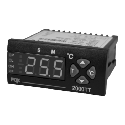
Conotec FOX-2000TT User manual

Conotec

Conotec FOX-2000TT User manual

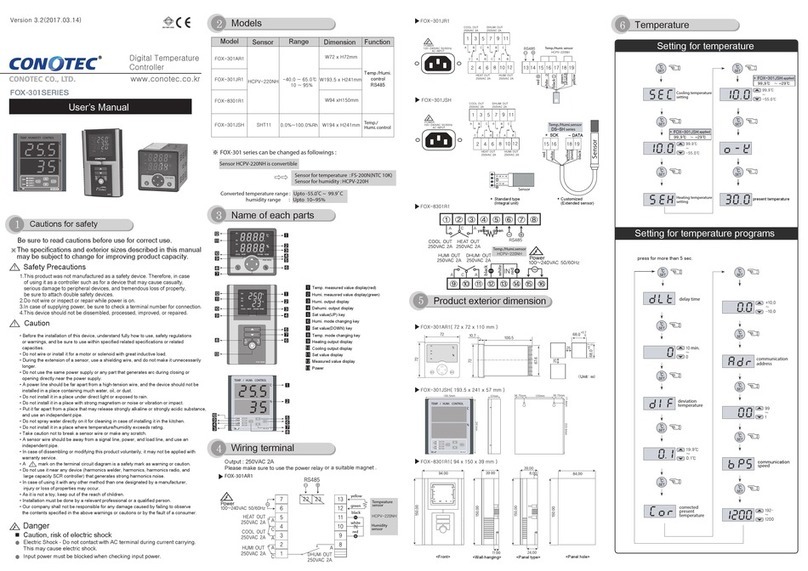
Conotec FOX-301 Series User manual

Conotec

Conotec FOX-301 Series User manual

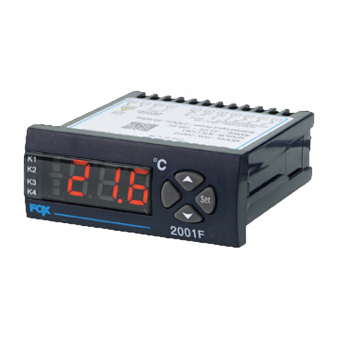
Conotec FOX-2004 User manual

Conotec

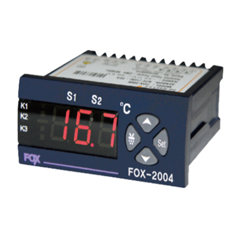
Conotec FOX-2004 User manual

Conotec FOX-23AF User manual

Conotec

Conotec FOX-23AF User manual

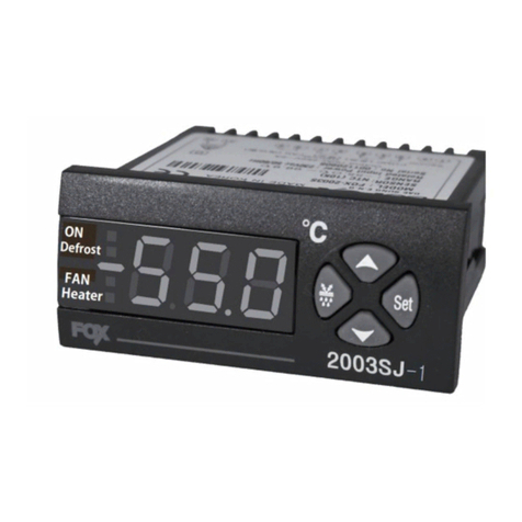
Conotec FOX-2003SJ-1 User manual

Conotec

Conotec FOX-2003SJ-1 User manual

Popular Temperature Controllers manuals by other brands

Proxel 3WM+A quick start guide

Proxel

Proxel 3WM+A quick start guide

THORLABS TC200 user guide

THORLABS

THORLABS TC200 user guide

Siemens RDF210 manual

Siemens

Siemens RDF210 manual

Siemens 1000 series Installation instruction

Siemens

Siemens 1000 series Installation instruction

Rehau Ba Technical installation manual

Rehau

Rehau Ba Technical installation manual

Greystone Energy Systems TSOB Series installation instructions

Greystone Energy Systems

Greystone Energy Systems TSOB Series installation instructions

RKC INSTRUMENT FZ110 Quick operation manual

RKC INSTRUMENT

RKC INSTRUMENT FZ110 Quick operation manual

Omron E5CC Quick Start Instruction

Omron

Omron E5CC Quick Start Instruction

THORLABS TED200C Operation manual

THORLABS

THORLABS TED200C Operation manual

Fuji Electric PXR3 Series instruction manual

Fuji Electric

Fuji Electric PXR3 Series instruction manual

Viessmann VITOTROL 100 Operating Instructions for the System User

Viessmann

Viessmann VITOTROL 100 Operating Instructions for the System User

West Control Solutions KS 45 Operation Notes

West Control Solutions

West Control Solutions KS 45 Operation Notes

AODE MACHINERY AWM-05A Operation & instruction manual

AODE MACHINERY

AODE MACHINERY AWM-05A Operation & instruction manual

Ropex CIRUS UPT-606 operating instructions

Ropex

Ropex CIRUS UPT-606 operating instructions

AKO AKO-16523 user manual

AKO

AKO AKO-16523 user manual

Stevens Smart PT user guide

Stevens

Stevens Smart PT user guide

Emerson E2 user manual

Emerson

Emerson E2 user manual

ActronControls LE75 operating instructions

ActronControls

ActronControls LE75 operating instructions

manuals.online logo
manuals.online logoBrands
  • About & Mission
  • Contact us
  • Privacy Policy
  • Terms and Conditions

Copyright 2025 Manuals.Online. All Rights Reserved.