manuals.online logo
Brands
  1. Home
  2. •
  3. Brands
  4. •
  5. Controlli
  6. •
  7. Controllers
  8. •
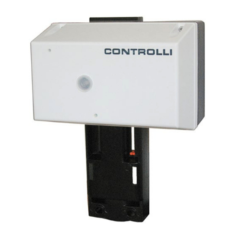
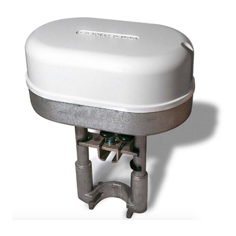
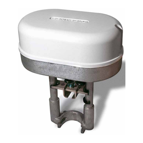
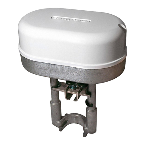
  9. Controlli MVH User manual

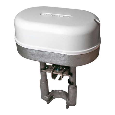
Controlli MVH User manual

CONTROLLI S.p.A. - 16010 Sant’Olcese (GE) - Italy
Tel. +39 010 73061 | Fax +39 010 7306870/871
[email protected] | www.controlli.eu
ISTRUZIONI DI MONTAGGIO / MOUNTING INSTRUCTIONS
Servocomandi per valvole
Valve actuators MVH
Assemble the actuator to the valve
by U-bolt (d) and the two nuts (e)
without locking the nuts.
Accoppiare il servocomando alla
valvola mediante la forcella (d) e
i due dadi (e) ma senza bloccare
i dadi.
Per/For MVH26/36/46/56/66
Per valvole corsa 16 e 25mm
• Abbassare lo stelo della valvola;
• bloccare la prolunga stelo c sulla
cremagliera in posizione tutta alzata
interponendo il disco indice a, la
rondella dentellata b ed il dado f
posizionato a circa metà della pro-
lunga stessa.
Per valvole corsa 45mm
• Abbassare lo stelo della valvola;
• bloccare la prolunga stelo c sulla
cremagliera in posizione tutta alzata
interponendo il disco indice ae la
rondella dentellata b.
For valve with 16 and 25mm stroke
• Lower the valve stem i
• lock the stem extension c on the
rack completely retracted placing
the indicator disk a, the jagged
washer b and the nut f positioned
half of the extension itself.
For valves with 45mm stroke
• Lower the valve stem;
• lock the stem extension c on the
rack completely retracted placing
the indicator disk a and the jagged
washer b.
Il uido all’interno della valvola può essere
molto caldo. Prima di rimuovere il servoco-
mando o aprire la valvola, assicurarsi che
il uido sia isolato e togliere pressione alla
valvola. L’operazione dev’essere eseguita
da personale esperto.
Attenzione: Non utilizzare il
servocomando disaccoppiato dalla
valvola.
Hot media hazard. Before removing actua-
tor from valve or opening the valve, ensure
that the valve control medium is isolated
and remove the pressure. Work must only
be carried out by a competent engineer.
Attention: do not use the actuator
disassembled from the valve.
1aEmissione / 1st Issue rev. b 12/19 TM DIM156
2
1a
1
1aEmissione / 1st Issue rev. c 09/2020 1 DIM156
By rotating the manual override
knob, lower the stem extension until
it reaches the valve stem, then rotate
the actuator to screw the stem into
the extension. Tighten the locknut on
the stem and lock the two nuts on
the U-bolt.
Ruotando la manopola del comando
manuale, far scendere la prolunga
stelo no a raggiungere lo stelo della
valvola, quindi ruotare il servocoman-
do per avvitare lo stelo nella prolunga.
Bloccare il controdado presente sullo
stelo e stringere i due dadi sulla forcella
per bloccare il servocomando.
Per/For MVH36A
• Alzare lo stelo della valvola;
• bloccare la prolunga stelo c sulla
cremagliera in posizione tutta alzata
interponendo il disco indice ae la
rondella dentellata b.
• Rise the valve stem;
• lock the stem extension c on the
rack completely retracted placing
the indicator disk a and the jagged
washer b.
Assemble the actuator to the valve
by U-bolt (d) and the two nuts (e)
without locking the nuts.
Accoppiare il servocomando alla
valvola mediante la forcella (d) e
i due dadi (e) ma senza bloccare
i dadi.
Per valvole corsa 16 e 25mm
• Alzare lo stelo della valvola;
• bloccare la prolunga stelo c sulla
cremagliera in posizione tutta alza-
ta interponendo il disco indice a, la
rondella dentellata b ed il dado f
posizionato a circa metà della pro-
lunga stessa.
• Rise the valve stem;
• lock the stem extension c on the rack
completely retracted placing the
indicator disk a, the jagged washer
b and the nut f positioned half of the
extension itself.
For valve with 16 and 25mm stroke
• Alzare lo stelo della valvola;
• bloccare la prolunga stelo c sulla
cremagliera in posizione tutta alza-
ta interponendo il disco indice a,
la rondella dentellata b ed il dado
f posizionato a circa metà della
prolunga stessa.
• Rise the valve stem;
• lock the stem extension c on the
rack completely retracted placing
the indicator disk a, the jagged
washer b and the nut f positioned
half of the extension itself.
2
1a
1
3
1aEmissione / 1st Issue rev. c 09/2020 2 DIM156
• Togliere il coperchietto e ruotare
il perno in senso orario facendo
fuoriuscire la cremagliera di quanto
basta per accoppiarla con lo stelo
della valvola; il perno può essere
bloccato incastrando una chiave
a forchetta come indicato in gura
• Ruotare il servocomando per avvi-
tare la prolunga sullo stelo della val-
vola, quindi bloccarla stringendo il
dado presente sullo stelo.
• Stringere i due dadi sulla forcella
per bloccare il servocomando.
• Togliere la chiave dal perno e mon-
tare il coperchietto.
• Raise the valve stem.
• Remove the cover and rotate the
pivot clockwise so that the rack
comes out for assembling it with the
valve stem; the pivot can be locked
by a spanner as shown in the picture.
• Rotate the actuator to screw the
extension on the valve stem, so lock
it tightening the nut on the stem.
• Tighten the two nuts on the U-bolt to
lock the actuator.
• Remove the key from the pivot and
mount the small cap.
Per/For MVH36C
1
3
Per valvole corsa 16 e 25mm
• Abbassare lo stelo della valvola;
• bloccare la prolunga stelo c sulla
cremagliera in posizione tutta
abbassata interponendo il disco
indice a, la rondella dentellata b ed
il dado f posizionato a circa metà
della prolunga stessa.
For valve with 16 and 25mm stroke
• Lower the valve stem;
• lock the stem extension c on the rack
completely extended placing the
indicator disk a, the jagged washer
b and the nut f positioned half of the
extension itself.
1a
Per valvole corsa 45mm
• Abbassare lo stelo della valvola;
• bloccare la prolunga stelo c sulla
cremagliera in posizione tutta
abbassata interponendo il disco
indice ae la rondella dentellata b.
For valves with 45mm stroke
• Lower the valve stem;
• lock the stem extension c on the
rack completely extended placing
the indicator disk a and the jagged
washer b.
• Togliere il coperchietto.
• Ruotare il perno in senso antiorario
di 1/2 giro e bloccarlo incastrando
una chiave a forchetta come indi-
cato in gura.
• Remove the cover.
• Rotate the pivot 1/2 turn coun-
ter-clockwise and lock it by a span-
ner as shown in the picture.
2
1aEmissione / 1st Issue rev. c 09/2020 3 DIM156
Screw the extension on the valve stem
until the groove on the actuator base
coincides with the one on the valve,
then lock the extension tightening the
nut on the stem. In case the two bases
do still not coincide, rotate the pivot until
it happens.
Avvitare la prolunga stelo sullo stelo della
valvola no a che la gola alla base del
servocomando coincida con quella
presente sulla valvola, quindi bloccare
la prolunga stringendo il dado presente
sullo stelo. Nel caso in cui, ad avvitamen-
to completato, le due gole non coinci-
dano ancora, ruotare il perno in senso
antiorario nché non coincideranno.
3
Accoppiare il servocomando
alla valvola mediante la forcel-
la (d) e i due dadi (e) ma senza
bloccare i dadi.
Assemble the actuator to the
valve by U-bolt (d) and the
two nuts (e) without locking
the nuts.
4
Gola / Groove
TARATURA CORSA SERVOCOMANDO (solo per MVH36/36A-
C/56)
• Svitare le viti di ssaggio sul coperchio e toglierlo.
• Utilizzando un cacciavite, agire sugli intagli presenti sugli
alberini dei due potenziometri ruotando in senso antiorario
il potenziometro destro e in senso orario il potenziometro
sinistro no al loro scontro meccanico.
• Agendo sulla manopola del comando manuale indicata
in g. 3 portare il disco indice ad entrambi gli estremi della
corsa e posizionarvi quindi i rispettivi indici mobili.
ACTUATOR STROKE CALIBRATION (only for MVH36/56)
• Loosen the locking screws located on the cover and put
it off.
• Using a screwdriver, turn counter-clockwise the right
potentiometer and clockwise the left one up to their
mechanical stop.
• Acting on the manual knob, as shown in g. 3, bring the
indicator disk to both stroke ends and position the related
adjustable indicators.
POSIZIONI DI MONTAGGIO / MOUNTING POSITIONS
1aEmissione / 1st Issue rev. c 09/2020 4 DIM156
COLLEGAMENTI ELETTRICI
Effettuare i collegamenti elettrici in conformità alle norme
vigenti e usando conduttori con sezione max 2,5 mm2.
Seguire le indicazioni utilizzando appositi morsetti (capicorda)
sui li di alimentazione in modo da prevenire contatti acciden-
tali tra cavi a differente voltaggio in caso di errata installazione.
Installare sulla linea di alimentazione un dispositivo di protezio-
ne conforme alle norme vigenti con soglia di intervento da 125
mA e con apertura contatti di almeno 3 mm (non compreso
nella fornitura).
ELECTRICAL CONNECTIONS
Perform the connections in compliance with existing rules and
using max 2,5 mm2cross section wires.
Follow the instructions by using wire terminals on power supply
wires in order to prevent accidental contacts between cables
at different voltages in case of wrong installation. On the power
supply line install a protection device compliant to existing rules
with a 125 mA intervention threshold and a minimum 3 mm
contact opening. The device is not supplied with the product.
MORSETTIERE
MVH36/56 (24 Vac)
MVH36A/C (24 Vac)
MVH26 (230 Vac)
MVH46 (24 Vac)
MVH66 (110 Vac)
L1 Fase Alimentazione
L2 Neutro 24V~+ 10%
M Comune
V+ Uscita +15 V (1)
Y Segnale di comando (2)
S1 Comune analogico
S2 0-10V o 0-200 MicroA (3)
S3 10-0V o 200-0 MicroA
COMANDO N-Y1 (**)
Alimentazione N-Y2 (***)
(**) Giunto si alza
(***) Giunto si abbassa
W1 Potenziometro
W2 ausiliario MVH
W3 26/46
Y1
N W1 W2 W3
Y2 L1
L2 S1 S2 S3
M V+ Y
1) Per il modello MVH36 Collegare il centrale del potenzio-
metro del regolatore (165 ohm) al morsetto Y, un laterale
al morsetto M e l’altro al morsetto V+.
2) Con ponticello SW3 in posizione A per segnale di comando
in aumento il giunto si muove verso l’alto
3) Collegare l’eventuale indicatore con ingresso in corrente ai
morsetti S3 (o S2) ed S1 (max 2mA). Collegare l’eventuale
indicatore con ingresso in tensione ai morsetti S3 (o S2) ed
M (max 2mA). Con giunto alzato il valore di corrente (o di
tensione) corrisponde al valore minimo.
TERMINALS
MVH36/56 (24 Vac)
MVH36A/C (24 Vac)
MVH26 (230 Vac)
MVH46 (24 Vac)
L1 Phase
power supplyL2 Neutral
24V~+ 10%
M Common
V+ +15 V Output (1)
Y Control signal (2)
S1 Analogue common
S2 0..10V or 0..200uA (3)
S3 10..0V or 200..0uA
Power supply N-Y1 (**)
control N-Y2 (***)
(**) Joint moves upwards
(***) Joint moves downwards
W1 Auxiliary
W2 potentiometer
W3 MVH 26/46
MVH66 (110 Vac)
Y1
N W1 W2 W3
Y2 L1
L2 S1 S2 S3
M V+ Y
1) For the model MVH36. Connect the central of the controller
potentiometer (165 ohm) to terminal Y, one side to terminal
M and the other one to terminal V+.
2) With jumper SW3 in A position and increasing control signal
the joint moves upwards.
3) Connect the eventual indicator to the current input at ter-
minals S3 (or S2) and S1 (max 2mA). Connect the indicator
with voltage input to terminals S3 (or S2) and M (max 2mA).
With joint up the voltage value (or current) corresponds to
the minimum value.
Il dispositivo contiene componenti elettrici ed elettronici e non può essere smaltito con i riuti domestici. Vanno rispettate le normative locali sullo smal-
timento.
The device contains electrical and electronic components and is not allowed to be disposed of as household refuse. All locally valid regulations and
requirements must be observed.
1aEmissione / 1st Issue rev. c 09/2020 5 DIM156
Le caratteristiche contenute in questa pubblicazione possono essere modicate senza
preavviso
The performances stated in this sheet can be modied without any prior notice

This manual suits for next models

5

Other Controlli Controllers manuals

Controlli MDL46 User manual

Controlli

Controlli MDL46 User manual

Controlli MVH56EA User manual

Controlli

Controlli MVH56EA User manual

Controlli MVE5 R Series User manual

Controlli

Controlli MVE5 R Series User manual

Controlli MVE2R Series User manual

Controlli

Controlli MVE2R Series User manual

Controlli SH 2 Series User manual

Controlli

Controlli SH 2 Series User manual

Controlli MVE5 R Series User manual

Controlli

Controlli MVE5 R Series User manual

Controlli MVT5 Series User manual

Controlli

Controlli MVT5 Series User manual

Controlli MVC503R User manual

Controlli

Controlli MVC503R User manual

Controlli MVC503 User manual

Controlli

Controlli MVC503 User manual

Controlli MVE2 Series User manual

Controlli

Controlli MVE2 Series User manual

Controlli MVH.FC User manual

Controlli

Controlli MVH.FC User manual

Controlli MVHFA User manual

Controlli

Controlli MVHFA User manual

Controlli NR9003 User manual

Controlli

Controlli NR9003 User manual

Controlli Energon NR9001 User manual

Controlli

Controlli Energon NR9001 User manual

Controlli MVE2 Series User manual

Controlli

Controlli MVE2 Series User manual

Controlli MVE2XX User manual

Controlli

Controlli MVE2XX User manual

Controlli MVE2 Series User manual

Controlli

Controlli MVE2 Series User manual

Controlli MVH56E User manual

Controlli

Controlli MVH56E User manual

Controlli MVE2 R-65 Series User manual

Controlli

Controlli MVE2 R-65 Series User manual

Controlli MVHFA User manual

Controlli

Controlli MVHFA User manual

Controlli MVE5 Series User manual

Controlli

Controlli MVE5 Series User manual

Controlli NR9000 User manual

Controlli

Controlli NR9000 User manual

Controlli MVE204S User manual

Controlli

Controlli MVE204S User manual

Controlli MVE2-65 Series Owner's manual

Controlli

Controlli MVE2-65 Series Owner's manual

Popular Controllers manuals by other brands

Omron SYSMAC One NSJ Series Operation manual

Omron

Omron SYSMAC One NSJ Series Operation manual

Axio AX-RAF-20D quick start guide

Axio

Axio AX-RAF-20D quick start guide

Star Progetti STAR 5 operating instructions

Star Progetti

Star Progetti STAR 5 operating instructions

Woodward EG-3P Installation and operation manual

Woodward

Woodward EG-3P Installation and operation manual

CEM Systems Ethernet Input Output Controller EIOC specification

CEM Systems

CEM Systems Ethernet Input Output Controller EIOC specification

Sullair SUPERVISOR CONTROLLER Operator's manual

Sullair

Sullair SUPERVISOR CONTROLLER Operator's manual

Watlow MLS-PM user guide

Watlow

Watlow MLS-PM user guide

Avaya WLAN 8100 Series quick start guide

Avaya

Avaya WLAN 8100 Series quick start guide

Dell PowerConnect W-3200 installation guide

Dell

Dell PowerConnect W-3200 installation guide

Nice METRO ME 3000 instruction manual

Nice

Nice METRO ME 3000 instruction manual

Sunricher SR-10 Series instructions

Sunricher

Sunricher SR-10 Series instructions

Memphis SBT2 manual

Memphis

Memphis SBT2 manual

Mitsubishi Electric QD70D4 user manual

Mitsubishi Electric

Mitsubishi Electric QD70D4 user manual

UltraLux RGBRF12MC instructions

UltraLux

UltraLux RGBRF12MC instructions

Samsan Korea CRN-96RC instruction manual

Samsan Korea

Samsan Korea CRN-96RC instruction manual

GSi PNEG-1894 installation manual

GSi

GSi PNEG-1894 installation manual

Rockwell Automation Allen-Bradley MicroLogix Reference manual

Rockwell Automation

Rockwell Automation Allen-Bradley MicroLogix Reference manual

ETATRON D.S. eSelect M 1 pH (Rx) Operating	instructions and maintenance

ETATRON D.S.

ETATRON D.S. eSelect M 1 pH (Rx) Operating instructions and maintenance

manuals.online logo
manuals.online logoBrands
  • About & Mission
  • Contact us
  • Privacy Policy
  • Terms and Conditions

Copyright 2025 Manuals.Online. All Rights Reserved.