manuals.online logo
Brands
  1. Home
  2. •
  3. Brands
  4. •
  5. Controlli
  6. •
  7. Controllers
  8. •
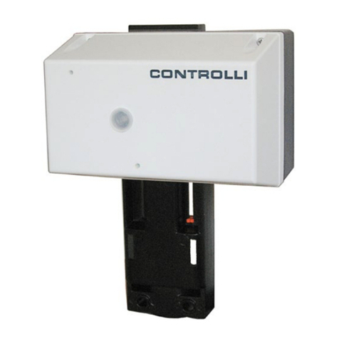
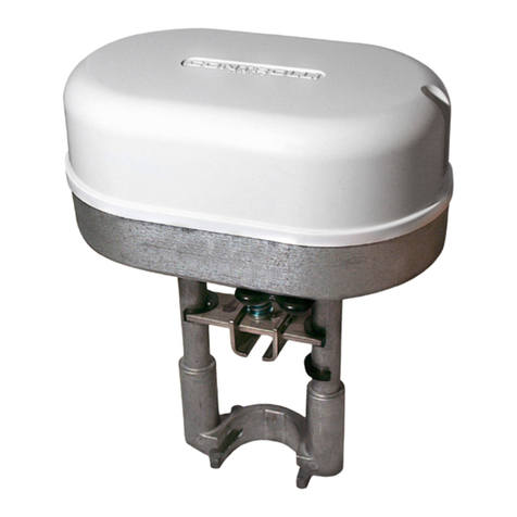
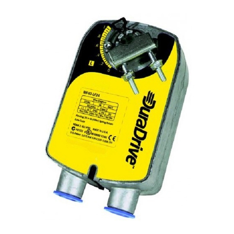
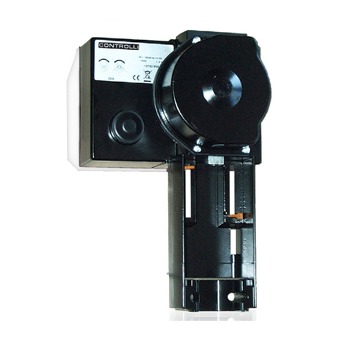
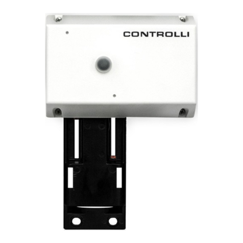
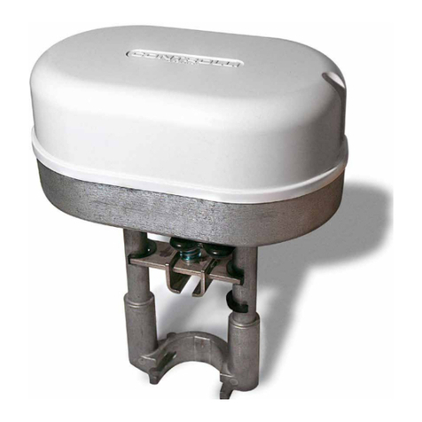
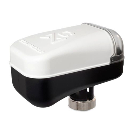
  9. Controlli MVHFA User manual

Controlli MVHFA User manual

CONTROLLI S.p.A. - 16010 Sant’Olcese (GE) - Italy
Tel. +39 010 73061 | Fax +39 010 7306870/871
[email protected] | www.controlli.eu
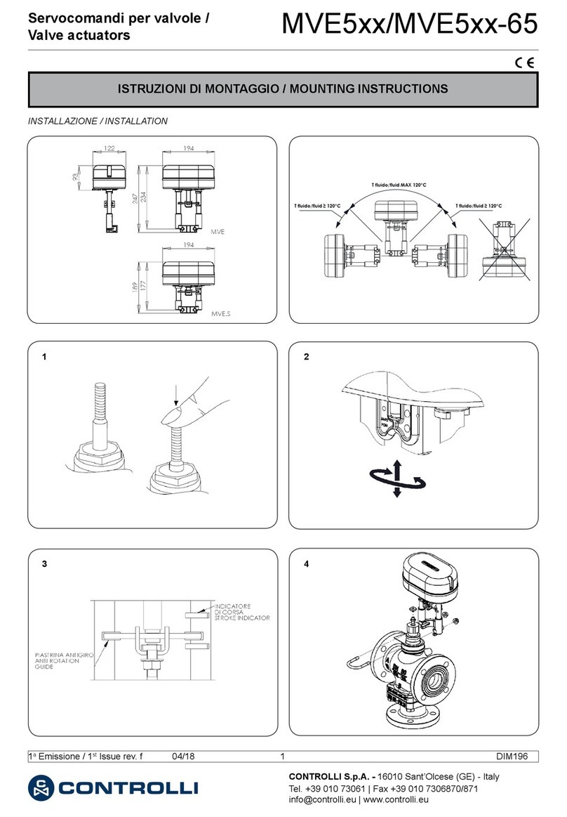
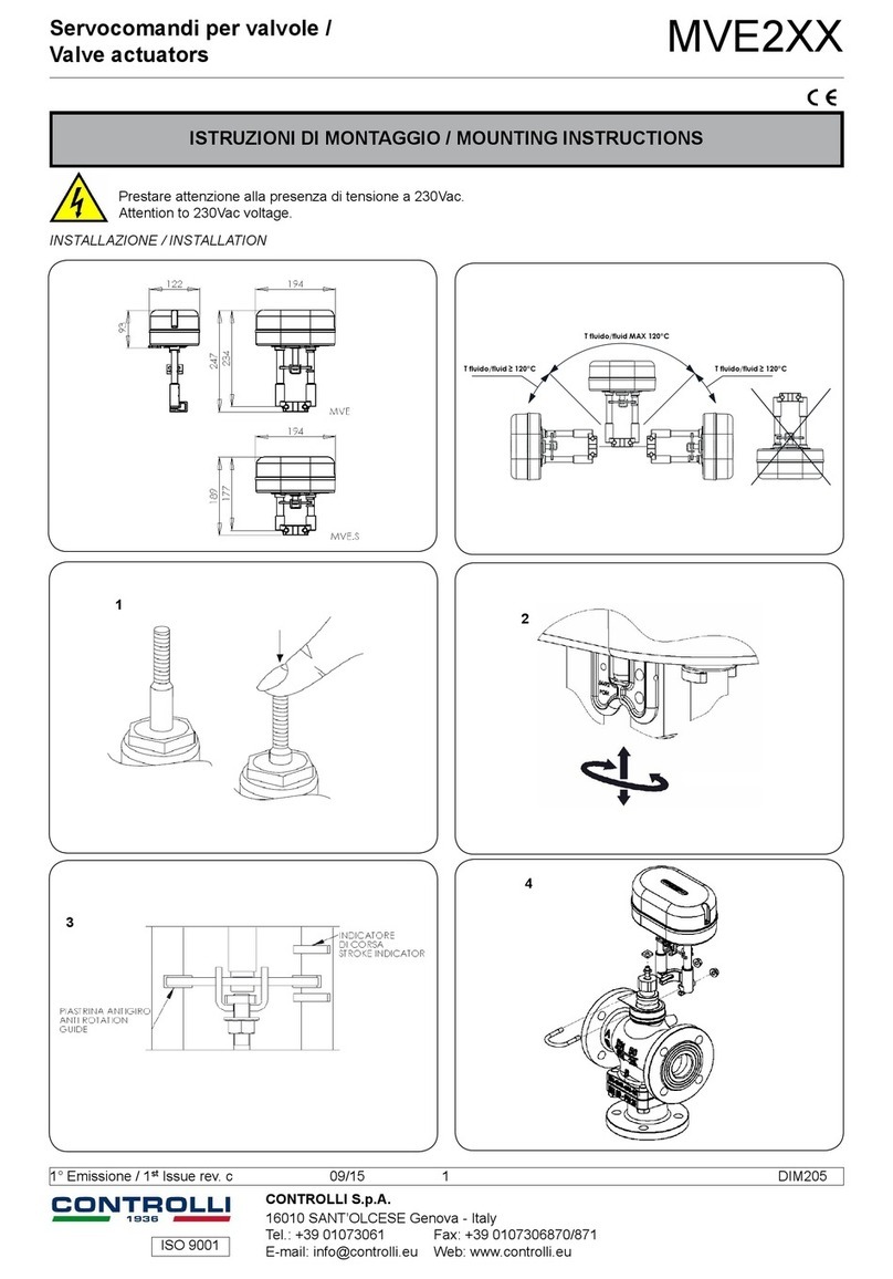
ISTRUZIONI DI MONTAGGIO / MOUNTING INSTRUCTIONS
MVH.FA
Il uido all’interno della valvola può essere molto caldo. Prima di rimuovere
il servocomando o aprire la valvola, assicurarsi che il uido sia isolato e
togliere pressione alla valvola. L’operazione dovrebbe essere eseguita da
personale esperto.
Attenzione: Non utilizzare il servocomando disaccoppiato dalla valvola.
Hot media hazard. Before removing actuator from valve or opening the
valve, ensure that the valve control medium is isolated and remove the
pressure. Work should only be carried out by a competent engineer.
Note: do not use the actuator disassembled from the valve.
• Alzare lo stelo della valvola;
• bloccare la prolunga stelo c sulla cremagliera in posizio-
ne tutta alzata interponendo il disco indice a, la rondella
dentellata b ed il dado f posizionato a circa metà della
prolunga stessa.
• Rise the valve stem;
• Lock the stem extension c on the rack completely retracted
placing the indicator disk a, the jagged washer b and the
nut f positioned half of the extension itself.
• Alzare lo stelo della valvola;
• bloccare la prolunga stelo c sulla cremagliera in posizione
tutta alzata interponendo il disco indice a e la rondella
dentellata b.
• Rise the valve stem;
• lock the stem extension c on the rack completely retract-
ed placing the indicator disk a and the jagged washer b.
Per valvole corsa 16 e 25mm
For valve with 16 and 25mm stroke
Per valvole corsa 45mm
For valves with 45mm stroke
Accoppiare il servocomando alla valvola mediante la forcella
(d) e i due dadi (e) ma senza bloccare i dadi.
Assemble the actuator to the valve by U-bolt (d) and the two
nuts (e) without locking the nuts.
Servocomandi per valvole con dispositivo di
ritorno in emergenza / Valve Actuator with spring return
1a Emissione / 1st Issue rev. a 04/2020 1DIM152
- Sollevare lo stelo della valvola.
- Togliere il coperchietto e ruotare il perno in senso orario facendo fuoriuscire la cre-
magliera di quanto basta per accoppiarla con lo stelo della valvola; il perno può
essere bloccato incastrando una chiave a forchetta come indicato in gura
- Ruotare il servocomando per avvitare la prolunga sullo stelo della valvola, quindi
bloccarla stringendo il dado presente sullo stelo.
- Stringere i due dadi sulla forcella per bloccare il servocomando.
- Togliere la chiave dal perno e montare il coperchietto.
- Raise the valve stem.
- Remove the cover and rotate the pivot clockwise so that the rack comes out for
assembling it with the valve stem; the pivot can be locked by a spanner as shown in
the picture.
- Rotate the actuator to screw the extension on the valve stem, so lock it tightening
the nut on the stem.
- Tighten the two nuts on the U-bolt to lock the actuator.
- Remove the key from the pivot and mount the small cap.
Rispettare le fasi nei collega-
menti in parallelo
* Cortocircuitare MX su G0 per livellare i potenziali di massa
* Short-circuit MX of G0 to level the ground potentials
Y
X1
MX
VC
G1
VH
G0
GG
0 V
24 V
~
G, G0= Max 100 m (328 ft.) ........................................... 1.5 mm² (AWG 15)
X1, MX, Y, VH, VC = Max 200 m (656 ft) ....................... 0.5 mm² (AWG 20)
Observe the phases during
the parallel connections
Terminal Function Description
G 24Vac/dc Power supply voltage
G0 24Vac rtrn
X1 Mod. Input (+) Modulating control signal
(0-10vdc)
Mx Mod. Input (-)
Vh Open input Control signal
short circuited on G0
Vc Close input
G1 16Vdc Auxiliary power supply
max. 25mA
(G0) Common
Y 2-10Vdc signal Position 0-100%
status indication
(G0) Common
Morsettiera Funzione Descrizione
G 24Vac/dc Tensione di alimentazione
G0 24Vac rtrn
X1 Ingresso mod. (+) Segnale di controllo
modulante (0-10Vdc)
MX Ingresso mod. (-)
VH Ingresso apri Segnale di controllo
cortocircuitati su G0
VC Ingresso chiudi
G1 16Vdc Alimentazione ausiliaria
max. 25mA
(G0) Comune
Y Segnale 2-10Vdc Indicazione stato
posizione 0-100%
(G0) Comune
24 Vac/dc
1a Emissione / 1st Issue rev. a 04/2020 2 DIM152
2
13
(0)
vedere impostazione dip a pag 4 e 5
see dip adjustment on page 4 e 5
vedere impostazione dip a pag 4 e 5
see dip adjustment on page 4 e 5
DIP OFF ON
12-10Vdc 0-5Vdc
2 proporzionale/proportional (MOD) 3 punti / 3 point (INC)
3---- Controllo in sequenza / Sequence Control
40-10Vdc 2-10Vdc
5
1-5V/ (con DIP n. 4 OFF / with DIP n. 4 OFF)
4-7V (con DIP n. 4 ON / with DIP n. 4 ON)
(con DIP n. 3 ON / with DIP n. 3 ON)
6-9V/ (con DIP n. 4 OFF / with DIP n. 4 OFF)
8-11V (con DIP n. 4 ON / with DIP n. 4 ON)
(con DIP n. 3 ON / with DIP n. 3 ON)
6temporizzazione 60s, 0% / running time 60s, 0%
(con DIP n. 2 ON / with DIP n. 2 ON)
temporizzazione 300s, 100% / running time 300s, 100% (con DIP
n. 2 ON / with DIP n. 2 ON)
7azione diretta / normal direction azione inversa / inverted direction
8 normale / normal lineare - logaritmico / linear - logarithmic
9 funzionamento / operation regolazione ne corsa / end position adjust
5
1a Emissione / 1st Issue rev. a 04/2020 3 DIM152
Direzione di chiusura della valvola / valve closure direction
10 V
Y =
2 V
Dettaglio selezione campi di lavoro / Range selection details
Funzionamento in posizione
OFF ON Descrizione
1 2-10 Vdc 0-5 Vdc Segnale di feedback
2 Modulante Increase/decrease Controllo (non in sequenza)
3 – Sequenza Controllo in sequenza
4 0-10 V 2-10 V Gamma tensione
5 1-5 V, 4-7 V 6-9 V, 8-11 V Parte gamma di tensione
6 60 s, 0% 300 s, 50% Temporizzazione
7 Normale Inverso Direzione del movimento
8 Normale Lineare/Logaritmico Caratteristica valvola
9 Funzionamento Regolazione ne corsa Funzionamento/regolazione ne
corsa
La scheda elettronica (vedere pagina
precedente) presenta nove interruttori. Il
prodotto è fornito con tutti gli interruttori
in posizione OFF.
1. Segnale di feedback 2-10/0-5 Vdc
I servocomandi MVHFA vengono forniti
con un segnale di feedback di 2 -10 e
0-5Vdc selezionabile tramite il Switch 1.
2. Segnale di comando (MOD/INC)
I servocomandi MVHFA possono essere
comandati da un segnale di comando
ottante a 3 punti (INC) o da segnale
modulante a variazione di tensione
(MOD).
3. Controllo in sequenza proporzionale
(---/SEQ)
Con la regolazione in sequenza (SEQ)
è possibile controllare due servoco-
mandi/valvole con un solo segnale di
comando.
Per ciascuno di questi è possibile sce-
gliere quale parte dei campi di tensione
utilizzare: la parte superiore 6-9V (8-11V)
o quella inferiore 1-5 V (4-7V). Vedere
anche capitolo “Selezione campi di
tensione parziali”.
Se l’interruttore NORM/INV è in posizione
NORM, la tensione più alta corrisponde
al 100% del usso e la più bassa allo 0%.
Per ottenere la funzione opposta, impo-
stare l’interruttore NORM/INV in posizione
INV.
4. Campi di tensione (0-10/2-10)
E’ possibile scegliere se utilizzare il campo
di tensione per segnale di regolazione
0-10V o 2-10V.
5. Selezione campi di tensione
(1-5, 4-7 / 6-9, 8-11)
E’ possibile scegliere quale parte del
campo di tensione utilizzare, quella
inferiore 1-5V (4-7V) o quella superiore
6-9V (8-11V).
Se l’interruttore è in posizione NORM, la
tensione maggiore corrisponde al 100%
del usso e la minore allo 0%.
Per ottenere la funzione opposta, impo-
stare l’interruttore NORM/INV in posizione
INV.
6. Temporizzazione (60s/300s)
Con il controllo increase/decrease, è
possibile scegliere una temporizzazione
1a Emissione / 1st Issue rev. a 04/2020 4DIM152
Le caratteristiche contenute in questa pubblicazione possono essere modifi cate senza preavviso
The performances stated in this sheet can be modifi ed without any prior notice
1a Emissione / 1st Issue rev. a 04/2020 5DIM152
Il dispositivo contiene componenti elettrici ed elettronici e non può essere smaltito con i riuti domestici. Vanno rispettate le normative locali sullo smal-
timento.
The device contains electrical and electronic components and is not allowed to be disposed of as household refuse. All locally valid regulations and
requirements must be observed.
Function in the Description
“OFF” pos. “ON” position
1 2-10 Vdc 0-5 Vdc Feedback signal
2 Modulating Increase/decrease Control (not at Sequence)
3 – Sequence Sequence control
4 0-10 V 2-10 V Voltage range
5 1-5 V, 4-7 V 6-9 V, 8-11 V Part of voltage range
6 60 s 300 s Running time
7 Normal Inverted Direction of movement
8 Normal Linear/Logarithmic Valve characteristic
9 Operation End position adjust Operation/End position adjustment
There are nine switches in a row on the
circuit board. On delivery (’Factory’), all
switches are in the “OFF” position.
1. Feedback signal 2-10 / 0-5 Vdc
MVHFA actuators are equipped with a 2
-10 and 0-5Vdc position feedback signal
selectable by Switch No 1.
2. Control signal (MOD/INC)
Actuator can either be controlled by a
variable direct voltage, a so called mod-
ulating signal (MOD), or by an increase/
decrease signal (INC).
3. Sequence or parallel control (---/SEQ)
With sequence (or parallel) control (SEQ),
two actuators/valves can be controlled
by only one control signal.
For each of these you can choose which
part of the voltage range to use, the
upper one, 6-9 V (8-11 V) or the lower
one, 1-5 V (4-7 V).
If the switch NORM / INV is in NORM po-
sition, the higher voltage corresponds
to 100% ow and the lower one to 0%.
With NORM / INV in the INV position you
will get the opposite function.
4. Voltage range (0-10 / 2-10)
You can choose whether to use the con-
trol signal voltage range 0-10 V or 2-10 V.
5. Part of voltage range (1-5, 4-7 / 6-9,
8-11)
You can choose which part of a volt-
age range to use, the lower one 1-5 V
(4-7 V) or the upper one 6-9 V (8-11 V).
If the switch is in the NORM position, the
higher voltage corresponds to 100% ow
and the lower one to 0%. To achieve the
opposite function, the switch should be
put in its INV position.
6. Running time 60 s / 300 s
With increase/decrease control, you
can choose a running time between
60 s or 300 s.
With modulating control, the running time
is always 15 s / 20 s / 30 s.
7. Direction of movement NORM / INV
When NORM is selected, the spindle of the
actuator moves inwards when the control
voltage decreases or if the actuator gets
a decrease signal.
With the switch NORM / INV, the direction
of movement can be changed.
8. Linearization (NORM / LIN/LG)
The motorized valve characteristics can
be modied. If you wish for the char-
acteristics to be affected, the setting
LIN/LG will make the characteristics of
an equally modied percentage (EQM)
valve almost linear.
On the other hand, with LIN/LG a motor-
ized valve equipped with a linear valve
will operate with ”Quick open charac-
teristics”. This means that with a small
control signal, the valve will be almost
completely open.
Note! For the actuator to register new
settings of the switches, the supply volt-
age must be cut, the settings done and
then the power on
or
the end position adjustment must be
done again (see point 9).
Refer also to illustration on page 2.
9.End position adjustment (OP / ADJ)
This switch is only used to adjust the end
positions when the actuator is commis-
sioned.
With powered actuator, momentarily put
the switch in the ON position. The actuator
will automatically nd the end positions of
the valve. At the end of the adjustment
all the other dip switch settings (1 to 8)
will be read again.
compresa tra 60s e 300s. Con azione
modulante la temporizzazione è sempre
15 s/20 s/30 s.
7. Senso di funzionamento (NORM / INV)
Quando viene impostato NORM, la vite
del servocomando si muove verso l’in-
terno del servocomando con:
- tensione di regolazione in diminuzione
(comando proporzionale)
oppure
- comando 3 punti in chiusura (VC)
Con l’interruttore NORM / INV si inverte
la direzione di azionamento.
8. Linearizzazione (NORM / LIN/LG)
Le caratteristiche di portata delle valvole
motorizzate possono essere modicate.
Se si desidera modicare tali caratteristi-
che, l’impostazione LIN/LG renderà quasi
lineare la caratteristica di una valvola
equipercentuale (EQM).
Al contrario, con LIN/LG una valvola
motorizzata dotata di caratteristica li-
neare funzionerà con “Caratteristica di
apertura veloce”. Questo signica che
un segnale di comando piccolo aprirà
la valvola quasi completamente.
Attenzione! Afnché il servocomando re-
gistri le nuove impostazioni degli interrut-
tori, occorre disalimentare e rialimentare
il servocomando
oppure
ripetere l’operazione di taratura ne
corsa
(vedi punto seguente)
Fare riferimento anche alle gure a pag.2.

Other manuals for MVHFA

2

Other Controlli Controllers manuals

Controlli MVC503R-MB User manual

Controlli

Controlli MVC503R-MB User manual

Controlli MVE5 R Series User manual

Controlli

Controlli MVE5 R Series User manual

Controlli NR9000 User manual

Controlli

Controlli NR9000 User manual

Controlli MVH56EA User manual

Controlli

Controlli MVH56EA User manual

Controlli MVC503R-MB User manual

Controlli

Controlli MVC503R-MB User manual

Controlli MVH56E User manual

Controlli

Controlli MVH56E User manual

Controlli MVT5 Series User manual

Controlli

Controlli MVT5 Series User manual

Controlli MVE5 Series User manual

Controlli

Controlli MVE5 Series User manual

Controlli MVT5 Series User manual

Controlli

Controlli MVT5 Series User manual

Controlli MVE2 R-65 Series User manual

Controlli

Controlli MVE2 R-65 Series User manual

Controlli MVH56E User manual

Controlli

Controlli MVH56E User manual

Controlli NR9000 User manual

Controlli

Controlli NR9000 User manual

Controlli MVH26 User manual

Controlli

Controlli MVH26 User manual

Controlli MVE5-65 Series User manual

Controlli

Controlli MVE5-65 Series User manual

Controlli MDL46 User manual

Controlli

Controlli MDL46 User manual

Controlli MVE5 R Series User manual

Controlli

Controlli MVE5 R Series User manual

Controlli MVE2 Series User manual

Controlli

Controlli MVE2 Series User manual

Controlli MVE2R Series User manual

Controlli

Controlli MVE2R Series User manual

Controlli W554C User manual

Controlli

Controlli W554C User manual

Controlli MVC503R User manual

Controlli

Controlli MVC503R User manual

Controlli MVHFA User manual

Controlli

Controlli MVHFA User manual

Controlli Energon User manual

Controlli

Controlli Energon User manual

Controlli MVH User manual

Controlli

Controlli MVH User manual

Controlli Energon NR9001 User manual

Controlli

Controlli Energon NR9001 User manual

Popular Controllers manuals by other brands

DeZurik LA Series Instruction

DeZurik

DeZurik LA Series Instruction

Koer C35-FC Technical manual

Koer

Koer C35-FC Technical manual

Emerson Fisher M Series instruction manual

Emerson

Emerson Fisher M Series instruction manual

Salus TRV10RFM instruction manual

Salus

Salus TRV10RFM instruction manual

Datapath VSN450 quick start guide

Datapath

Datapath VSN450 quick start guide

Honeywell SLATE installation instructions

Honeywell

Honeywell SLATE installation instructions

Pioneer BSG175A8R user manual

Pioneer

Pioneer BSG175A8R user manual

Covaris S220 Service note

Covaris

Covaris S220 Service note

Schnick-Schnack-Systems Long Distance Controller user guide

Schnick-Schnack-Systems

Schnick-Schnack-Systems Long Distance Controller user guide

Norac UC4+ installation manual

Norac

Norac UC4+ installation manual

Unitronics Vision OPLC V130-33-TA24 installation guide

Unitronics

Unitronics Vision OPLC V130-33-TA24 installation guide

Strand C21 Operation guide

Strand

Strand C21 Operation guide

Microfan DRAMM MIST TIME manual

Microfan

Microfan DRAMM MIST TIME manual

iLight SCI0405 instruction manual

iLight

iLight SCI0405 instruction manual

EasyIO FG-32 user guide

EasyIO

EasyIO FG-32 user guide

Comnet FVT109B Installation and operation manual

Comnet

Comnet FVT109B Installation and operation manual

Seagull REC user manual

Seagull

Seagull REC user manual

National Instruments NI cRIO-9065 user manual

National Instruments

National Instruments NI cRIO-9065 user manual

manuals.online logo
manuals.online logoBrands
  • About & Mission
  • Contact us
  • Privacy Policy
  • Terms and Conditions

Copyright 2025 Manuals.Online. All Rights Reserved.