manuals.online logo
Brands
  1. Home
  2. •
  3. Brands
  4. •
  5. Controlli
  6. •
  7. Controllers
  8. •
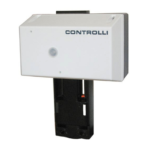
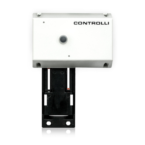
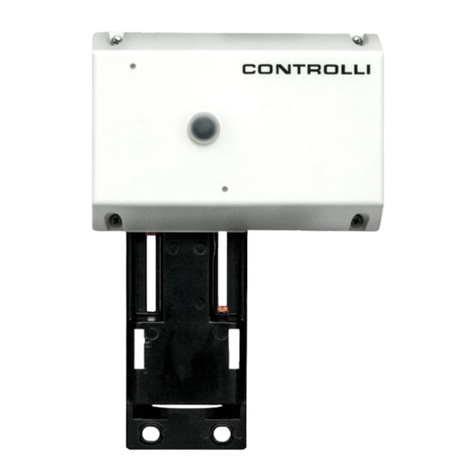
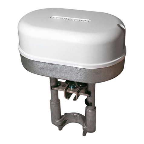
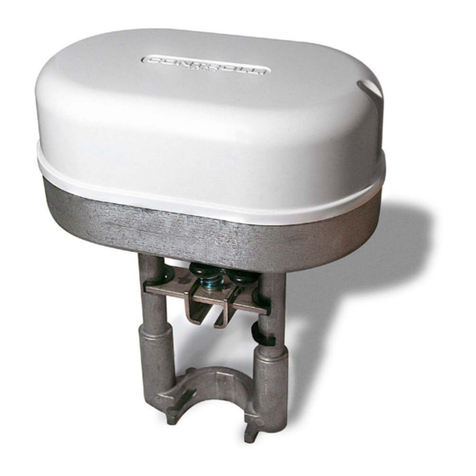
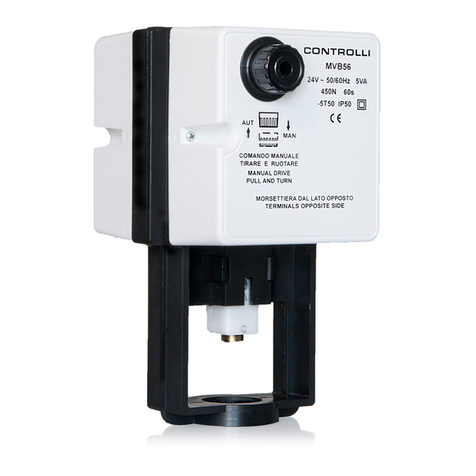
  9. Controlli MVB User manual

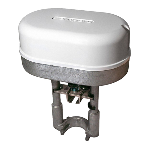
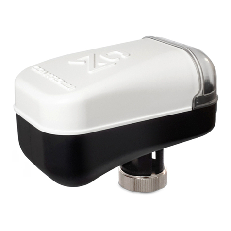
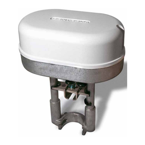
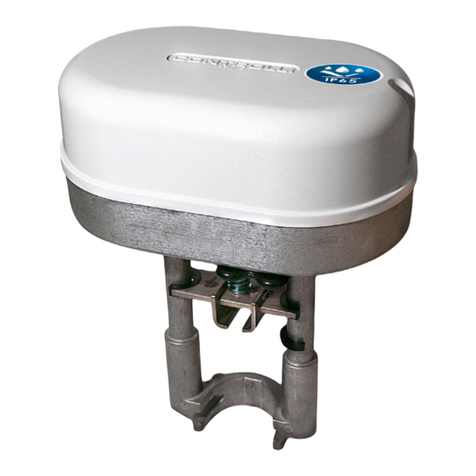
Controlli MVB User manual

CONTROLLI S.p.A. - 16010 Sant’Olcese (GE) - Italy
Tel. +39 010 73061 | Fax +39 010 7306870/871
[email protected] | www.controlli.eu
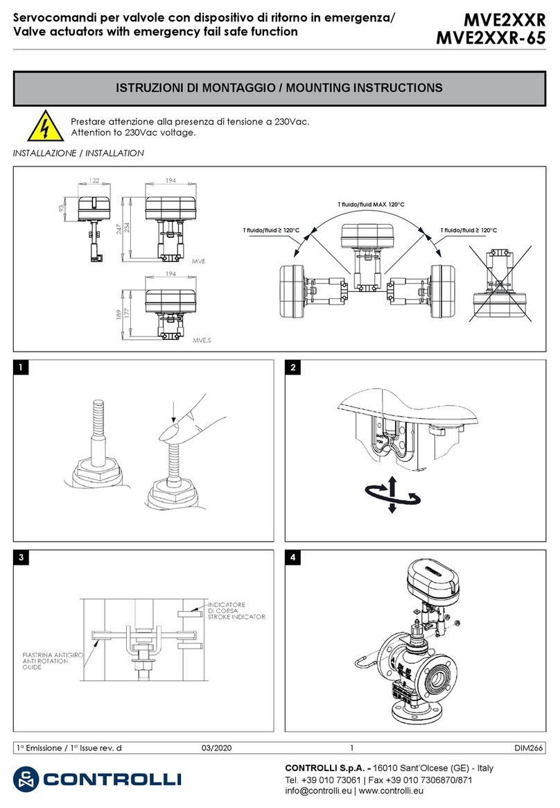
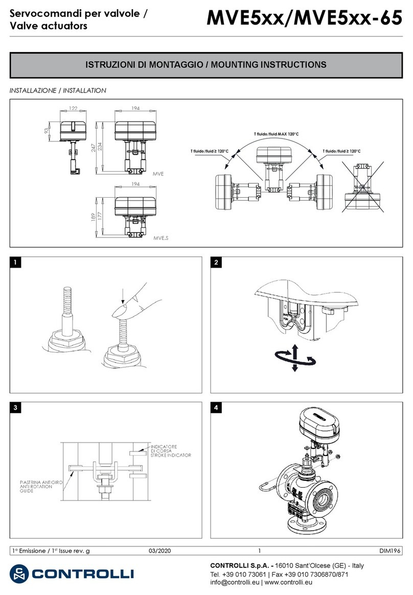
ISTRUZIONI DI MONTAGGIO / MOUNTING INSTRUCTIONS
Servocomandi per valvole MVB
INSTALLAZIONE
Per le applicazioni nelle quali la temperatura del uido non
supera i 120 °C il servocomando può essere montato in qua-
lunque posizione, altrimenti deve essere montato in posizione
orizzontale.
Lasciare uno spazio di circa 10 cm al di sopra e lateralmente
per accedere alle parti interne, alla morsettiera per i collega-
menti elettrici e per le operazioni di montaggio-smontaggio.
MONTAGGIO SU VALVOLE VSB-VMB/VSBF-VMBF, VSBPM-
VMBPM/VSBPMF-VMBPMF e 2-3TGB (Fig. 1 + Fig. 1a)
• Estrarre e ruotare in senso antiorario la manopola del co-
mando manuale (1) no a far giungere a scontro mec-
canico superiore il giunto.
• Per VMB-VSB/VSBF-VMBF e 2-3TGB: estrarre e ruotare in
senso orario (max. 1/4 di giro) la manopola (1) no ad
incontrare la prima posizione di rientro a scatto.
• Per VMBPM-VSBPM/VMBPMF-VSBPMF: estrarre e ruotare
in senso orario (max. 1/2 di giro) la manopola (1) no ad
incontrare la seconda posizione di rientro a scatto.
• Assicurarsi che l’otturatore sia a battuta superiore alzan-
do lo stelo della valvola.
• Per 2-3TGB: avvitare il controdado (5) no a ne letta-
tura, avvitare la prolunga stelo (6), serrare il controdado
con la prolunga stelo.
• Qualora fosse necessario un distanziatore per alte tem-
perature, inserire l’accessorio MVBHT (4) sul collo della
valvola.
• Posizionare il servocomando sulla valvola interponendo
la ghiera (3) tra lo stelo e la staffa.
• Ruotare il servocomando no a che la staffa vada ad
appoggiarsi sul piano della valvola.
• Serrare la ghiera (3) utilizzando la chiave in dotazione.
• Tenendo fermo lo stelo valvola forzare in senso antiorario
la parte terminale ad esagono del giunto (2) (con funzio-
ne di controdado) no a strapparla.
• Riavvitare, quindi, la parte strappata in senso orario no
a serrarla sul resto del giunto, bloccando così lo stelo val-
vola.
INSTALLATION
The actuator can be mounted in any position for applications
in which the uid temperature is not higher than 120 °C, oth-
erwise it should be mounted in horizontal position.
It is necessary to leave 10 cm. above and beside it, so as to
operate on the internal parts, on the terminal board for the
electric connections and for assembling-disassembling oper-
ations.
VSB-VMB/VSBF-VMBF, VSBPM-VMBPM/VSBPMF-VMBPMF and
2-3TGB VALVES ASSEMBLY (Fig. 1 + Fig. 1a)
• Pull and turn counter-clockwise the manual knob (1) until
the joint reaches the upper mechanical stop.
• For VMB-VSB/VSBF-VMBF e 2-3TGB: pull out the knob (1)
and rotate clockwise (max 1/4 turn) until it enters the rst
rest position.
• For VMBPM-VSBPM/VMBPMF-VSBPMF: pull out the knob
(1) and rotate clockwise (max 1/2 turn) until it enters the
second rest position.
• Make sure the plug reaches upper seat by lifting the
valve stem.
• For 2-3TGB: screw the lock nut (5) to the end of the
thread, screw the stem extension (6), tighten the lock nut
with the stem extension.
• If a spacer for high temperatures is needed, insert the
MVBHT accessory (4) onto the valve neck.
• Position the actuator on the valve interposing the ring nut
(3) between the stem and the mounting bracket.
• Rotate the actuator until the bracket rests on the valve
body.
• Tighten the ring nut (3) using the supplied spanner.
• Keeping the valve stem steady, force counter-clockwise
the lower hexagonal part of joint (2) (which acts as a
locknut) until it detaches.
• Then screw clockwise the part which has been detached
so as to tighten it on the rest of the joint, thus blocking the
valve stem.
5
6
Fig. 1 Fig. 1a
VSB/VMB 2-3TGB
1aEmissione / 1st Issue rev. a 03/2020 1 DIM001
TARATURA CORSA SERVOCOMANDO SOLO PER CORSA DI-
VERSA DA 16,5 mm
• Togliere il coperchio lato opposto alla manopola.
• In caso di MVB52/56, vericare che il ponticello SW2 sia
su A (Fig. 2).
• Alimentare il servocomando tra L1 e L2 con morsetto Y
scollegato.
• Attendere che il servocomando raggiunga il ne corsa
inferiore.
• Collegare il positivo del voltmetro al morsetto S2 e il ne-
gativo al morsetto M.
• Ruotare il trimmer P1 no a leggere 0 V sul voltmetro.
COLLEGAMENTI ELETTRICI
Eseguire i collegamenti come da schema indicato qui di se-
guito ed in conformità alle norme vigenti.
MORSETTIERA
- MVB2. (230 V~)
- MVB46 (24 V~)
LEGENDA
Y1 = Giunto si alza
N = Comune Comando
(1)
Y2 = Giunto si abbassa
Fig. 2
SOLO PER MVB 36-52-56 / ONLY FOR MVB 36-52-56
ACTUATOR STROKE CALIBRATION ONLY FOR STROKES DIFFER-
ENT FROM 16.5 mm
• Remove the back cover (opposite the knob).
• For MVB52/56 only, make sure that jumper SW2 is in A po-
sition (Fig. 2).
• Supply the actuator between L1 and L2 terminals with Y
terminal disconnected.
• Wait the actuator to reach the lower stroke end.
• Connect the positive of the voltmeter to S2 terminal and
the negative to M.
• Rotate P1 trimmer until the voltmeter indicates 0 V.
ELECTRICAL CONNECTIONS
Perform the electrical connections according to the follow-
ing diagrams and in compliance with existing rules.
TERMINAL BOARD
- MVB2. (230 V~)
- MVB46 (24 V~)
LEGEND
Y1 = Joint up
N = Common Control (1)
Y2 = Joint down
1aEmissione / 1st Issue rev. a 03/2020 2 DIM001
Le caratteristiche contenute in questa pubblicazione possono essere modifi cate senza preavviso
The performances stated in this sheet can be modifi ed without any prior notice
MORSETTIERA
- MVB5.
- MVB36
(*) Internamente connessi
LEGENDA
L1 = Fase 24 V~ ±10%
alimentazione
L2 = M = Comune
M = Comune
V+ = Uscita 15 V- (2)
Y = Segnale di comando (3)
S3 = 10...0V- or 200...0 µA
S2 = 0...10V- or 0...200 µA (4)
S1 = Comune analogico
(1) Con tensione fra N (Comune) Y1 (fase dal contatto del re-
golatore): il giunto del servocomando si alza. Con tensione
fra N e Y2 il giunto si abbassa. Senza tensione il servoco-
mando rimane nella posizione assunta.
(2) Per il modello MVB36 collegare il cursore del potenziometro
del regolatore (165 Ω) al morsetto Y, un laterale al morsetto
M e l’altro al morsetto V+.
(3) Con ponticello SW2 in posizione C (Vedi g. 2) e con se-
gnale in aumento, il giunto si muove verso il basso.
(4) Collegare l’indicatore con ingresso in corrente ai morsetti
S3 (o S2) e S1. Collegare l’indicatore con ingresso in ten-
sione ai morsetti S3 (o S2) ed M. Il valore estremo sinistro di
tensione (corrente) corrisponde a giunto alzato.
NOTA
I servocomandi MVB dispongono dei seguenti accessori:
D36 contatto microausiliario con camma registrabile;
MVBHT distanziatore per alte temperature;
244 riscaldatore stelo;
MVBD microinterruttore AUT/MAN - montabile solo in fabbri-
ca;
MVBC Protezione antipioggia - grado di protezione IP53.
Per ulteriori dettagli fare riferimento alle istruzioni di montaggio
relative (DIM004 e DIM023 solo per 244).
Scheda con potenziometro ausiliario (MVBPA2) disponibile
solo su richiesta, in sede di ordine servocomando e montato
in fabbrica.
TERMINAL BOARD
- MVB5.
- MVB36
(*) Internally connected
LEGEND
L1 = Phase 24 V~ ±10%
power supply
L2 = M = Common
M = Common
V+ = 15 V- Output (2)
Y = Control signal
(3)
S3 = 10...0V- or 200...0 µA
S2 = 0...10V- or 0...200 µA (4)
S1 = Analogue common
(1) With voltage between N (Common) and Y1 (phase from
controller contact): the actuator joint moves upwards. With
voltage between N and Y2 the joint moves downwards. Wi-
thout voltage the actuator remains in the position gained.
(2) For MVB36: connect the controller potentiometer cursor
(165 Ω) to Y terminal, one end to M and the other to V+
terminal.
(3) When SW2 jumper is in C position (See Fig. 2) and signal
increases, the joint moves downwards.
(4) Connect the indicator with input current to S3 (or S2) and
S1 terminals. Connect the indicator with input voltage to S3
(or S2) and M terminals. The extreme left voltage (current)
value corresponds to joint up.
NOTE
MVB actuators are available the following accessories:
D36 micro auxiliary contact with adjustable cam;
MVBHT spacer for high temperatures;
244 stem heater;
MVBD AUT/MAN microswitch - Only factory-mounted;
MVBC Rainproof protection - protection degree IP53.
For further details make reference to the relevant mounting
instructions (DIM004 and DIM023 only for 244).
P.C. board with an auxiliary potentiometer (MVBPA2) available
only on request when ordering an
actuator and factory-mounted.
Il dispositivo contiene componenti elettrici ed elettronici e non può essere smaltito con i riuti domestici. Vanno rispettate le normative locali sullo smal-
timento.
The device contains electrical and electronic components and is not allowed to be disposed of as household refuse. All locally valid regulations and
requirements must be observed.
1aEmissione / 1st Issue rev. a 03/2020 3 DIM001

This manual suits for next models

8

Other Controlli Controllers manuals

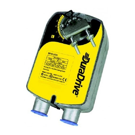
Controlli MVT5 Series User manual

Controlli

Controlli MVT5 Series User manual

Controlli DuraDrive MX40-7 User manual

Controlli

Controlli DuraDrive MX40-7 User manual

Controlli MVC503R-MB User manual

Controlli

Controlli MVC503R-MB User manual

Controlli MVE522-65 User manual

Controlli

Controlli MVE522-65 User manual

Controlli MVC503 User manual

Controlli

Controlli MVC503 User manual

Controlli MVH56EX User manual

Controlli

Controlli MVH56EX User manual

Controlli MVE5 R Series User manual

Controlli

Controlli MVE5 R Series User manual

Controlli MVE5 Series User manual

Controlli

Controlli MVE5 Series User manual

Controlli MVH.FC User manual

Controlli

Controlli MVH.FC User manual

Controlli MVT203 User manual

Controlli

Controlli MVT203 User manual

Controlli MVH56EA User manual

Controlli

Controlli MVH56EA User manual

Controlli MVC503R User manual

Controlli

Controlli MVC503R User manual

Controlli NR9000 User manual

Controlli

Controlli NR9000 User manual

Controlli MVE2R Series User manual

Controlli

Controlli MVE2R Series User manual

Controlli MVH User manual

Controlli

Controlli MVH User manual

Controlli Energon NR9001 User manual

Controlli

Controlli Energon NR9001 User manual

Controlli SH 2 Series User manual

Controlli

Controlli SH 2 Series User manual

Controlli Energon NR9001 User manual

Controlli

Controlli Energon NR9001 User manual

Controlli MVE522 User manual

Controlli

Controlli MVE522 User manual

Controlli MVE2 Series User manual

Controlli

Controlli MVE2 Series User manual

Controlli MVHFA User manual

Controlli

Controlli MVHFA User manual

Controlli MVH56E User manual

Controlli

Controlli MVH56E User manual

Controlli MVH56E User manual

Controlli

Controlli MVH56E User manual

Controlli MVE2 R Series User manual

Controlli

Controlli MVE2 R Series User manual

Popular Controllers manuals by other brands

Nitrous Express MAXIMIZER-II Installation and user manual

Nitrous Express

Nitrous Express MAXIMIZER-II Installation and user manual

BLACK DEVICES Garage Guardian quick start guide

BLACK DEVICES

BLACK DEVICES Garage Guardian quick start guide

Regin Regio Eddo Instruction

Regin

Regin Regio Eddo Instruction

TREND CNC2 Installation Instructions - Fixing

TREND

TREND CNC2 Installation Instructions - Fixing

LOVATO ELECTRIC LRD Series manual

LOVATO ELECTRIC

LOVATO ELECTRIC LRD Series manual

Black Stone BL 982411-0 instruction manual

Black Stone

Black Stone BL 982411-0 instruction manual

Computherm WPR-100GE operating instructions

Computherm

Computherm WPR-100GE operating instructions

socorex PROFILLER 435 operating instructions

socorex

socorex PROFILLER 435 operating instructions

Full Gauge Controls TC-900i power Operation instructions

Full Gauge Controls

Full Gauge Controls TC-900i power Operation instructions

Penn TC3X21 installation guide

Penn

Penn TC3X21 installation guide

Sony JumboTron JME-SA200 Service manual

Sony

Sony JumboTron JME-SA200 Service manual

Rockwell Automation Allen-Bradley Micro800 instruction manual

Rockwell Automation

Rockwell Automation Allen-Bradley Micro800 instruction manual

Sunforce 60021 manual 

Sunforce

Sunforce 60021 manual 

CHROMATEQ CLUB-E 1024 quick start guide

CHROMATEQ

CHROMATEQ CLUB-E 1024 quick start guide

Siemens SINUMERIK 828D Turning operating manual

Siemens

Siemens SINUMERIK 828D Turning operating manual

Moen ARC-4200 installation guide

Moen

Moen ARC-4200 installation guide

Kemo Electronic M028N quick guide

Kemo Electronic

Kemo Electronic M028N quick guide

Emerson Unidrive SPM user guide

Emerson

Emerson Unidrive SPM user guide

manuals.online logo
manuals.online logoBrands
  • About & Mission
  • Contact us
  • Privacy Policy
  • Terms and Conditions

Copyright 2025 Manuals.Online. All Rights Reserved.