Cordivari 5240000000034 User manual

www.cordivari.com
www.cordivaridesign.com
Cod. 1910000001159 - nv02
5240000000034 - 5240000000035 - 5240000000036
5240000000051 - 5240000000052 - 5240000000053

- 2 - Cod. 1910000001159 - nv02
IT - Istruzioni d’uso .................................................... pag. 4
EN - User manual ..................................................... pag. 8
FR - Notice d’emploi ................................................... pag. 12
DE - Gebrauchsanweisung . . . . . . . . . . . . . . . . . . . . . . . . . . . . . . . . . . . . . . . . . . . page 16
................................................... pag. 20

- 3 -Cod. 1910000001159 - nv02
1. Destinazione d'uso .................................................... pag. 4
2. Caratteristiche tecniche ................................................ pag. 4
3. Installazione ......................................................... pag. 4
3.1 Avvertenze....................................................... pag. 4
3.2 Procedura di installazione ........................................... pag. 4
3.3 Riarmo automatico del termostato..................................... pag. 5
4. Condizioni di esercizio................................................. pag. 5
5. Manutenzione ........................................................ pag. 5
6. Smaltimento ......................................................... pag. 5
Italiano
- 4 - Cod. 1910000001159 - nv02
Pertanto dopo l’installazione e l’avvio dell’impianto occorre assicurarsi
gestione dell’impianto.
I riscaldatori elettrici ad immersione con termostato di regolazione e di
sicurezza sono destinate ad essere utilizzate come fonte ausiliaria di
riscaldamento all’interno dei bollitori (preparatori di acqua calda sanitaria
ad accumulo). Il costruttore declina ogni responsabilità per danni
materiali o corporali riconducibili ad utilizzi impropri dell’apparecchio
o per installazioni non conformi alle presenti istruzioni, mancanza o
imperizia d’uso, o a causa del mancato rispetto delle norme di sicurezza
elettriche vigenti nel paese di utilizzo dell’apparecchio.
IMPORTANTE! La scelta della resistenza elettrica più idonea allo
2. Caratteristiche tecniche
Riscaldatori elettrici utilizzabili come integrazione sui bollitori, conformi
all’utilizzo con acqua potabile, secondo D.M. 174/04 e D.L. n°31, forniti
• elementi riscaldanti in acciaio inossidabile
• Classe di protezione IP 44
• termostato di regolazione (30+/-8/70+/-4°C) e termostato di sicurezza
(90 +/- 5 °C) a riarmo manuale. I valori di temperatura indicati sono
soggetti a tolleranza in conformità con le norme EN60730-1, EN60730-
2-9 e possono discostarsi rispetto alla temperatura rilevata in utenza,
anche oltre tali tolleranze, a causa dei naturali fenomeni termodinamici
• Manopola di regolazione
•
L
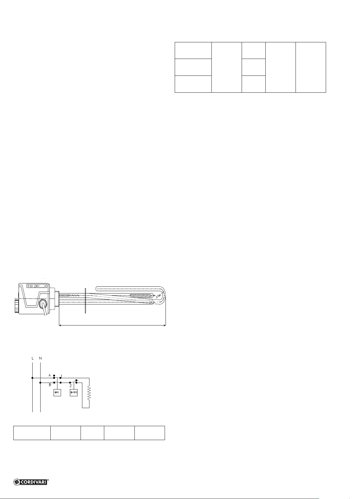
Schema elettrico
L
Codice Tensione
Potenza
Lunghezza L
Raccordo R
5240000000034
5240000000051
Monofase
50/60Hz
1,5
320 1"1/2
5240000000035
5240000000052 2
5240000000036
5240000000053 3
3. Installazione
3.1 Avvertenze
•
conformemente alle istruzioni, da un professionista avente la
qualsiasi condizione di rischio.
•
l’alimentazione elettrica.
•
corrispondenza della dotazione di serie degli accessori (guarnizione e
parti della resistenza ed evitare di sovrapporre pesi anche imballata.
• Controllare che la tensione di alimentazione alla quale si andrà a
collegare il riscaldatore sia conforme a quella stampigliata sulla
resistenza stessa (± 10%) e Il circuito di alimentazione elettrica
risponda alla normativa vigente.
•
• Assicurarsi che l’impianto sia provvisto del collegamento a terra.
• Non curvare la resistenza ed assicurarsi che lo spazio disponibile
all’interno ed all’esterno del serbatoio sia compatibile con le dimensioni
e gli ingombri per il montaggio del riscaldatore.
• Il riscaldatore va montato in modo che la resistenza risulti in posizione
orizzontale e sempre completamente immersa, preferibilmente nella
parte bassa del serbatoio per un migliore scambio termico.
• Il riscaldatore non deve assolutamente essere messo in funzione se
la resistenza non è completamente immersa.
•
sedimentazioni.
• Collegare il riscaldatore alla rete elettrica interponendo un organo di
interruzione di caratteristiche adeguate.
• Il circuito di alimentazione elettrica del’apparecchio deve essere
(30 mA max).
•
giallo-verde > terra
altri colori > fasi.
3.2 Procedura di installazione
• Posizionare la guarnizione.
• Avvitare il riscaldatore nella connessione del bollitore indicata dal
costruttore dello stesso, in caso di connessione disponibile di diametro
superiore è ammesso l’uso di una riduzione (utilizzare riduzioni in
acciaio o ghisa, evitare elementi in ottone, rame o altro materiale
ad elevato potenziale elettrico). Evitare che la connessione sia
complessivamente più lunga di 100 mm.
• Serrare il riscaldatore con una chiave idonea applicando una coppia
non superiore a di 10 kgm, per il serraggio NON applicare torsioni al
contenitore esterno del riscaldatore.
•
idraulica del collegamento.
• Procedere alla connessione elettrica seguendo le avvertenze di cui sopra.
• Regolare il termostato alla temperatura desiderata.
Italiano
Istruzioni d’uso

- 5 -Cod. 1910000001159 - nv02
Italiano
CH 75
3.3 Riarmo automatico del termostato
ATTENZIONE: prima di intraprendere qualsiasi operazione accertarsi
che non ci sia e non possa accidentalmente esserci tensione elettrica.
E' quindi necessario disconnettere l'alimentazione elettrica.
1
3
2
4
• Togliere la vite posizionata sulla custodia di protezione delle
connessioni elettriche, vite che dà accesso al pulsante di riarmo del
termostato. 12
• Premere il pulsante di riarmo del termostato utilizzando un attrezzo
con una impugnatura elettricamente isolata. 3
• Riposizionare la vite nella sua sede. 4
4. Condizioni di esercizio
Rispettare eventuali normative circa la massima temperatura di
stoccaggio delle’acqua calda sanitaria.
Il riscaldatore deve essere utilizzato entro i limiti di temperatura indicati
(e mai con temperatura superiore a 100°C) ed esclusivamente per
riscaldare acqua priva di impurità o elementi inquinanti (rispondente
ai requisiti di UNI CTI 8065 e/o D.L. n. 31 del 02/02/01 e s.m.i.) e con
durezza compresa tra 7 e 20°Fr.
AVVERTENZA: In presenza di acqua con un valore di durezza
>20°F (dove 1°F=grado francese=10mg CaCo3/l), per preservare
l’ecienza della resistenza elettrica è obbligatorio installare
un adeguato sistema (addolcitore o dosatore di condizionanti)
per ridurre la formazione di calcare all'interno del bollitore e/o
prevedere la pulizia periodica della resistenza, facendo attenzione
a non danneggiarla in nessun modo. Danni e malfunzionamenti
derivanti da fenomeni di depositi calcarei invalidano le condizioni
di garanzia.
Assicurarsi che l’ambiente in cui viene installata la resistenza risponda
1.
kg di acqua per kg di aria secca (cfr tabella).
2. Posizionamento lontano da fonti di calore e in zona ben aerata
Temperatura 0 °C 20 °C 30 °C 40 °C 50 °C
Max Umidità
relativa 100% 100% 60% 33% 20%
5. Manutenzione
• Tutte le operazioni di installazione, cablaggio e controllo devono
• In caso di intervento del termostato di sicurezza occorre un controllo
riarmo manuale del termostato stesso.
• Se il cavo di alimentazione risulta danneggiato, esso va sostituito a
6. Smaltimento
metallici vanno ceduti ad operatori autorizzati alla raccolta dei
-
ti non metallici vanno ceduti ad operatori autorizzati al loro
smaltimento.
-
milabili agli urbani pertanto nel rispetto dei regolamenti comunali del co-
domestico.

- 6 - Cod. 1910000001159 - nv02

- 7 -Cod. 1910000001159 - nv02
1. Intended use ......................................................... pag. 8
2. Technical features..................................................... pag. 8
3. Installatione.......................................................... pag. 8
3.1 Warnings ........................................................ pag. 8
3.2 Installation procedure .............................................. pag. 8
3.3 Thermostat manual reset............................................ pag. 9
4. Operating conditions .................................................. pag. 9
5. Maintenance ......................................................... pag. 9
6. Disposal............................................................. pag. 9
English

- 8 - Cod. 1910000001159 - nv02
This document is intended for the installer and end user. Therefore, after
system installation and start-up, make sure that it is delivered to the end
user or to the manager of the system.
1. Intended use
Electric immersion heaters with control and safety thermostat are
intended to be used as an auxiliary heating source inside the boilers
(preparatory to hot water accumulation). The manufacturer disclaims
any liability for damage or injury due to misuse of the equipment or for
of grounding and tampering, poor maintenance and lack of experience of
use, or because of failure to comply with the electrical safety regulations
in force in the country of use of the item.
IMPORTANT! The choice of electric resistance element which is most
installer.
2. Technical features
Electric heaters for integrated use on boilers, compliant for use with
drinking water, according to
• stainless steel heating elements
• IP 44 protection class
• Control thermostat (30+/-8/70+/-4°C) and manual reset safety
thermostat (90 +/- 5 °C) . The temperature values shown are subject to
tolerances in compliance with standards EN60730-1, EN60730-2-9 and
may deviate from the temperature measured at the tap, even beyond
these tolerances, due to the natural thermodynamic phenomena of
• Setting knob
•
L
Wiring diagram
L
Art. nr. Tension
Output
Width L
5240000000034
5240000000051
Single-
phase
50/60Hz
1,5
320 1"1/2
5240000000035
5240000000052 2
5240000000036
5240000000053 3
3. Installation
3.1 Warnings
• Electric heater installation must be performed in accordance with
• Remember to disconnect electrical power before installation.
• Check the integrity of the heater in all his components and equipments
(gasket and power cable). Do not tamper with any part of the electric
heater and avoid to place weight over it, also when packaged.
• Check that the power voltage to which the heater will be connected
complies with that stamped on the resistance element itself (±
10%) and that the power supply circuit is in compliance with current
legislation in force.
• Make sure the line cables are dimensioned according to the power.
• Make sure the installation has been correctly grounded.
• Do not bend resistance element and ensure the space available inside
and outside the tank is compatible with dimensions and space required
for mounting the heater.
• The heater should always be assembled so that the resistance element
is in a horizontal position and always completely immersed, preferably
in the lower part of the tank in order to achieve a better heat exchange.
• The heater must never be operated if the resistance element is not
completely immersed.
• Avoid installation in areas of the boiler where sedimentation can occur.
• Connect the heater to the electrical grid by interposing a break device
with the appropriate characteristics.
•
circuit breaker with high sensitivity (30 mA max).
• The electrical connection must respect the colours of each single
yellow-green > earth
other colours > phases.
3.2 Installation procedure
• Position the gasket.
• Screw in the heater in the boiler connection indicated by the
manufacturer. Use a reduction if the connection available is of a larger
diameter (use adapter in cast iron or stainless steel, avoid components
in brass or copper or any other material with high conductivity power).
Avoid the connection to be more than 100mm.
• Tighten the heater with a suitable wrench, applying a tightening torque
no greater than 10kg for the tightening , do not apply torsion to the
external case of the heater.
•
of the connection.
• Proceed with electrical connection following the warnings above.
• Adjust the thermostat to the desired temperature.
English
User manual

- 9 -Cod. 1910000001159 - nv02
English
CH 75
3.3 Thermostat manual reset
personnel before resetting of the safety thermostat.
ATTENTION: before undertaking any operations, make sure there
is not and cannot there accidentally be power supply. It is therefore
necessary to unplug the power supply.
1
3
2
4
• Remove the screw located on the protective casing of the electrical
connections and which provides access to the thermostat reset button.
12
• Press the thermostat reset button using a tool with an electrically
insulated grip. 3
• .4
4. Operating conditions
Comply with all regulations about the maximum hot water storage
temperature.
The heater must be used within the above stated temperature limits (for
no reason with a temperature higher than 100°C) and exclusively to
warm drinkable water, deprived of any impurity or polluting substances
and with hardness included within 7 and 20°Fr.
WARNING:
In case of water with hardness value >20°F (where 1°F=French
degree=10mg CaCo3/l), to preserve heating element eciency, it
is necessary to install a suitable system (softener or conditioning
agent dispenser) to reduce the formation of lime scale inside boiler
and/or proceed with a periodic cleaning of the heating element,
avoiding carefully any damage. Damages and malfunctions arising
from lime scale deposits will void product warranty.
accumulation circuit.
Make sure that environment of installation respect the following
requirements
1. Ambient temperature included between 5°C and 45 °C and humidity
.
2. Heater placed far from heat sources and in areas with good ventilation.
Temperature 0 °C 20 °C 30 °C 40 °C 50 °C
Max relative
humidity 100% 100% 60% 33% 20%
5. Maintenance
• All installation, wiring and checks must be performed after having
disconnected the power supply.
• In the event of intervention on the safety thermostat, have the system
checked by a skilled operator before manually resetting the thermostat.
•
electrician.
6. Disposal
At the end of technical life cycle of the product, its metallic
components must be given to an authorised metallic
materials collection operator for recycling, while non-metallic
components shall be given to operators authorised for their
disposal. Products must be dealt with, if disposed of by the end user,
as assimilable to urban refuse, therefore in compliance with municipal
regulations. It should not in any case be treated as household waste.

- 10 - Cod. 1910000001159 - nv02

- 11 -Cod. 1910000001159 - nv02
1. Usage prévu ......................................................... pag. 12
2. Caractéristiques techniques ............................................ pag. 12
3. Installation........................................................... pag. 12
3.1 Avertissements ................................................... pag. 12
3.2 Procédure d’installation ............................................. pag. 12
3.3 Réarmement manuel du thermostat ................................... pag. 13
4. Conditions d’exercic................................................... pag. 13
5. Entretien ............................................................ pag. 13
6. Traitement ........................................................... pag. 13
Français

- 12 - Cod. 1910000001159 - nv02
Pour cela, au terme de l’installation et du démarrage de l’appareil, il est
au responsable de la gestion de l’installation.
1. Usage prévu
et de sécurité sont destinés à être utilisés comme source auxiliaire de
sanitaire à accumulation). Le fabricant décline toute responsabilité dans
le cas de dommages matériels ou corporels dérivant d’une utilisation
impropre de l’appareil ou dans le cas d’installations non conformes aux
d’altération, de mauvaise maintenance et de mauvaise utilisation, ou en
cas de non-respect des normes de sécurité électriques en vigueur dans
le pays d’utilisation de l’appareil.
IMPORTANT! Le choix de la résistance électrique la plus appropriée à
2. Caractéristiques techniques
•
• Classe de protection IP 44
• thermostat de réglage (30+/-8/70+/-4 °C) et thermostat de sécurité (90
+/- 5 °C) à réarmement manuel. Les valeurs de température indiquées
sont soumises à des tolérances conformément aux normes EN60730-
niveau du service, même au-delà de ces tolérances, en raison des
• Bouton de réglage
•
L
Schéma électrique
L
Code Tension
Puissance
Largeur L
Raccord R
5240000000034
5240000000051
Monophasé
50/60Hz
1,5
320 1"1/2
5240000000035
5240000000052 2
5240000000036
5240000000053 3
3. Installation
3.1 Avertissements
•
nécessaires requises par les réglementations en vigueur de manière à
éviter toute condition de risque.
• Avant de réaliser l’installation ne pas oublier de couper l’alimentation
électrique.
•
(joint et câble), Ne pas superposer d’autres poids sur l’appoint, même
s’il est encore emballé
•
raccordé, soit conforme à la tension estampillée sur la résistance en
question (± 10%) et que le circuit d’alimentation électrique répond aux
normes en vigueur.
•
• S’assurer de la mise à terre de l’installation.
• Ne pas plier la résistance et s’assurer que la longueur plongeante soit
compatible avec le diamètre libre du ballon
•
résistance soit en position horizontale et soit toujours complétement
un meilleur échange thermique.
•
résistance n’est pas complètement immergée.
• Eviter d’installer dans des zones, à l’intérieur du ballon, où des dépôts
pourraient apparaître par la suite.
•
organe d’interruption de caractéristiques appropriées.
• Le circuit d’alimentation électrique de l’appareil doit être protégé par
.
• Durant le branchement électrique respecter les couleurs des
jaune-vert > terre
autres couleurs > phases.
3.2 Procédure d’installation
• Positionner le joint.
• dans la connexion du ballon indiquée par le
fabricant du ballon, en cas de connexion disponible au niveau supérieur,
il est possible d’utiliser une réduction. Utiliser des réductions d’acier ou
de fonte. Evitez l’étain, le cuivre ou autre matériel très conductible.
Eviter que la connexion soit plus longue de 100mm.
•
serrage inférieur à 10 kgm. Lors du serrage ne pas faire appui ou
torsion sur le capot de l’appoint.
• Procéder au remplissage du ballon de manière à contrôler la bonne
étanchéité du raccordement.
• Procéder au branchement électrique en suivant les avertissements
indiqués ci-dessus.
• Régler le thermostat à la température désirée.
Français
Notice d’emploi

- 13 -Cod. 1910000001159 - nv02
Français
CH 75
3.3 Réarmement manuel du thermostat
ATTENTION: avant d’entreprendre une quelconque opération, vérier
qu’il n’y ait pas et qu’il ne puisse pas y avoir accidentellement de tension
électrique. Il est par conséquent nécessaire de couper l’alimentation
électrique.
1
3
2
4
• Retirer la vis placée sur la protection des connexions électriques; cette vis
donne accès au bouton de réarmement du thermostat. 12
• Appuyer sur le bouton de réarmement du thermostat à l’aide d’un outil
dont la poignée est électriquement isolée. 3
• 4
4. Conditions d’exercice
Respecter les éventuelles réglementations concernant la température
maximum de stockage de l’eau chaude sanitaire.
L’appoint doit être utilisé dans les limites de températures sous-indiquées et
des eaux dénuées d’impuretés ou d’éléments agressifs et avec une dureté
comprise entre 7 et 20 °Fr.
MISE EN GARDE :
Si la dureté de l'eau est >20 °fH (où 1 °fH = degré français = 10mg
CaCo3/l), an de préserver le bon fonctionnement de la résistance
électrique il faut obligatoirement installer un système approprié
(adoucisseur ou doseur d’agents conditionnants) pour réduire la
formation de calcaire à l'intérieur du chaue-eau et/ou prévoir un
nettoyage régulier de la résistance, en veillant à ne pas l'endommager.
Les dommages et les dysfonctionnements dus aux dépôts de calcaire
rendent la garantie nulle.
En présence d’impuretés prévoir des philtres en amont du ballon.
S’assurer que le local de la résistance répond aux conditions suivantes
1.
kg d’air sec (cf tableau).
2. Positionnée loin d’autres sources de chaleur et en zones bien aérées
Temperature 0 °C 20 °C 30 °C 40 °C 50 °C
Max humidité
relative 100% 100% 60% 33% 20%
5. Entretien
• Toutes les opérations d’installation, de câblage et de contrôle doivent être
• En cas d’intervention du thermostat de sécurité il est nécessaire de faire
réarmement manuel du thermostat en question.
• Si le câble d’alimentation est endommagé il doit être remplacé par un
6. Traitement
Au terme du cycle de vie du produit, les composants métalliques
doivent être remis aux opérateurs autorisés à la collecte des ma-
les composants non métalliques doivent être remis aux opérat-
eurs autorisés à procéder à leur élimination. Les produits doivent
aux déchets urbains dans le respect des réglementations communales. Dans
tous les cas le produit ne doit pas être traité comme déchet domestique.

- 14 - Cod. 1910000001159 - nv02

- 15 -Cod. 1910000001159 - nv02
1. Zweck der Anlage ..................................................... pag. 16
2. Technische Merkmale.................................................. pag.. 16
Installation.............................................................. pag. 16
3.1 Hinweise ........................................................ pag. 16
3.2 Installationsschritte ................................................ pag. 16
3.3 Manuelles Reset des Thermostats .................................... pag. 17
4. Betriebsbedingungen .................................................. pag. 17
5. Wartung . . . . . . . . . . . . . . . . . . . . . . . . . . . . . . . . . . . . . . . . . . . . . . . . . . . . . . . . . . . . . pag. 17
6. Entsorgung .......................................................... pag. 17
Deutsch

- 16 - Cod. 1910000001159 - nv02
Die vorliegende Bedienungsanleitung ist für den Installationsfachmann
und den Endbenutzer vorgesehen. Daher muss nach Installation und
Inbetriebnahme der Anlage sichergestellt werden, dass die Anleitung
dem Endbenutzer bzw. der für den Anlagenbetrieb verantwortlichen.
1. Zweck der Anlage
Die elektrischen Taucherhitzer mit Regulier- und Sicherheitsthermostat
sind als Reserveheizquelle im Boiler vorgesehen (Speicher -
Brauchwarmwasseraufbereiter). Der Hersteller haftet nicht für
Materialschäden bzw. Schäden am Maschinenkorpus, die durch
Zweckentfremdung des Geräts bzw. durch nicht der Bedienungsanleitung
entsprechende Installation verursacht wurden, von Abwesenheit
Unerfahrenheit in Gebrauch, oder im Falle von Nichtbeachtung der
landesüblichen elektrischen Sicherheitsnormen im Umgang mit dem
Gerät.
WICHTIG! Die Wahl eines zweckentsprechenden elektrischen
Widerstandes obliegt Ihrem Planungs- bzw. Installationsfachmann.
2. Technische Merkmale
Elektrische Erhitzer, die als Ergänzung an Boilern eingesetzt werden
können, Konform für den Einsatz mit Trinkwasser, zweite D.M. 174/04 e
• Heizelemente aus rostfreiem Stahl
• Schutzart IP 44
• Regelthermostat (30+/-8/70+/-4 °C) und Sicherheitsthermostat
(90 +/- 5 °C) mit manueller Rücksetzfunktion. Die angegebenen
Temperaturwerte unterliegen den Toleranzen gemäß den Normen
EN60730-1, EN60730-2-9 und können aufgrund der natürlichen
thermodynamischen Phänomene von Wassersystemen, wie z. B.
Schichtung, Konvektionsbewegungen usw., von der beim Anwender
gemessenen Temperatur auch über diese Toleranzen hinaus
abweichen.
• Regelknopf
•
L
Schaltplan
L
Art. Nr. Spannung
Leistung
Länge L
Anschluss R
5240000000034
5240000000051
Einphasen-
schaltung
50/60Hz
1,5
320 1"1/2
5240000000035
5240000000052 2
5240000000036
5240000000053 3
3. Installation
3.1 Hinweise
• Die Installation des elektrischen Erhitzers muss gemäß der
und im Einklang mit den geltenden Richtlinien vorgenommen werden,
um jedwede Risikosituation auszuschließen.
•
•
Serienmäßig mitgelieferten Zubehörteile (Dichtung und Netzkabel)
vom Heizstab und vermeiden Sie das stapeln dieser Erhitzer auch im
verpackten Zustand.
• Sicherstellen, dass die Netzspannung, an die der Erhitzer
angeschlossen wird, den auf dem Widerstand eingeprägten Werten
entspricht (± 10%) und das die Elektrische Hausanlage den aktuellen
Normen entspricht.
• Überprüfen, dass die Kabel der Leitung entsprechend der Leistung bemaßt
sind.
• Sich vergewissern, dass die Anlage geerdet ist.
• Den Widerstand nicht biegen und darauf achten dass im innerhalb und
außerhalb des Speichers ausreichend Platz je nach der Länge und
Einbauvolumen für den Heizstab vorhanden ist.
• Der Erhitzer muss immer so montiert werden, dass der Widerstand
horizontal positioniert ist und immer komplett eingetaucht ist,
wenn Möglich im unteren Teil des Speicher um einen besseren
Wärmeaustausch zu haben.
• Der Erhitzer darf niemals in Betrieb genommen werden, wenn der
Widerstand nicht komplett eingetaucht ist.
• Das Gerät nicht an Stellen im Erhitzer montieren, an denen sich
Ablagerungen bilden können.
• Den Erhitzer an das Stromnetz anschließen und ein Sperrelement mit
entsprechenden Merkmalen zwischenschalten
•
• Beim Stromanschluss müssen die Farben der einzelnen Leiter
gelb-grün > Erde
andere Farben > Phasen.
3.2 Installationsschritte
• Die Dichtung verlegen.
• Das Heizgerät am vom Hersteller angegebenen Anschluss des
Warmwasserspeichers anschrauben, Bei einem Anschluss mit
größerem Durchmesser kann ein Reduzierteil eingesetzt werden
(verwenden Sie Reduktionen aus Stahl oder Guss, verweiden Sie
Teile aus Messing, Kupfer oder ähnliche Materialien die einen hohe
Trägerfähigkeit haben). Der Anschluss darf nicht länger als 100 mm
sein.
• Den Erhitzer mit einem entsprechenden Schlüssel anziehen mit
einem maximalen Drehmoment von 10 Kg/m, zum festziehen nicht am
äußeren Gehäuse drehen.
• Den Boiler füllen, um die hydraulische Dichtheit des Anschlusses zu
testen.
• Den Stromanschluss gemäß der obigen Bedienungsanleitung
Deutsch
Gebrauchsanweisung

- 17 -Cod. 1910000001159 - nv02
Deutsch
vornehmen.
• Den Thermostat auf die gewünschte Temperatur einstellen.
CH 75
3.3 Manuelles Reset des Thermostats
Es ist ratsam die Installation von Fachpersonal überprüfen zu lassen,
bevor das Reset des Sicherheitsthermostats durchgeführt wird.
ACHTUNG: Vor Beginn der Arbeiten sicherstellen, dass keine
Spannung anliegt und dass der Stromversorgung nicht versehentlich
angelegt werden kann. Es ist daher notwendig, die Stromversorgung
abzutrennen.
1
3
2
4
• Entfernen Sie die Schraube am Schutzgehäuse der elektrischen
Taste am Thermostat. 12
• Drücken Sie die Reset-Taste am Thermostat mit einem Werkzeug,
3
• Schraube an ihrem Sitz anbringen. 4
4. Betriebsbedingungen
Eventuelle Richtlinien hinsichtlich der max. Speichertemperatur des
Brauchwarmwassers beachten.
Der Heizstab darf nur innerhalb der angegebenen Temperaturlimit
verwendet werden (niemals über 100° C) und ausschließlich zur
Wasserhärte zwischen 7 und 20° Fr.
HINWEIS: Für Wasser, das einen Härtegrad von über 20 °F (1
°F=französischer Härtegrad=10 mg CaCo3/l) aufweist, muss ein
geeignetes System zur Erhaltung der Ezienz des Heizelements
(Enthärter oder Dosierer von Konditionierungsüssigkeit) installiert
werden, um die Kalkablagerungen im Warmwasserspeicher zu
reduzieren. Zudem muss das Heizelement regelmäßig gereinigt
werden, wobei darauf zu achten ist, dass es nicht beschädigt wird. Im
Fall von Schäden und Betriebsstörungen durch Kalkablagerungen
wird die Garantie ungültig.
Bei verunreinigten Wasser muss ein Filter im Trinkwasservorlauf
installiert werden
Sicherstellen, dass die Umgebung, in der der Widerstand installiert ist,
1.
0,015 kg Wasser pro kg trockene Luft (vergl. Tabelle).
2. Positionierung nicht in Nähe von Heizquellen und in gut gelüfteten
Räume.
Temperatur 0 °C 20 °C 30 °C 40 °C 50 °C
Max relative
Feuchtigkeit 100% 100% 60% 33% 20%
5. Wartung
•
erst vorgenommen werden, nachdem die Stromzufuhr unterbrochen
wurde.
•
Bediener die Anlage vor dessen manueller Rückstellung kontrollieren.
• Sollte das Stromkabel schadhaft sein, muss dieses von einem
6. Entsorgung
Am Ende der praktischen Lebensdauer der Anlage müssen
die Metallteile Firmen zugeführt werden, die zur Sammlung
und entsprechenden Wiederverwertung von Metallteilen
berechtigt sind. Nicht metallische Bauteile hingegen müssen
Firmen übergeben werden, die zur Entsorgung dieser Teile
berechtigt sind. Die Geräte müssen, so diese vom Endbenutzer entsorgt
werden, wie Stadtmüll im Einklang mit den kommunalen Bestimmungen
der Zugehörigkeitsgemeinde behandelt werden. Auf keinen Fall darf
dieses Gerät wie normaler Hausmüll entsorgt werden.

- 18 - Cod. 1910000001159 - nv02

- 19 -Cod. 1910000001159 - nv02
1. Προορισμός χρήσης................................................... pag. 4
2. Τεχνικά χαρακτηριστικά ................................................ pag. 4
3. Εγκατάσταση......................................................... pag. 4
.................................................. pag. 4
........................................... pag. 4
....................................... pag. 5
4. Συνθήκες εργασίας .................................................... pag. 5
5. Συντήρηση........................................................... pag. 5
6. Διάθεση ............................................................. pag. 5

- 20 - Cod. 1910000001159 - nv02
ΣΗΜΑΝΤΙΚΟ!
•
•
•
•
•
L
Διάγραμμα συνδεσμολογίας
L
5240000000034
5240000000051
50/60Hz
1,5
320 1"1/2
5240000000035
5240000000052 2
5240000000036
5240000000053 3
3.1 Προειδοποιήσεις
•
•
•
•
•
•
•
•
•
•
•
•
mA Max).
•
>
> .
3.2 Διαδικασίες εγκατάστασης
•
•
•
•
This manual suits for next models
5
Table of contents
Languages:
Other Cordivari Heater manuals

Cordivari
Cordivari PUFFER VC VT User manual

Cordivari
Cordivari Claudia User manual

Cordivari
Cordivari Claudia User manual
Cordivari
Cordivari Badge Elettrico User manual

Cordivari
Cordivari CLAUDIA BLOWER MISTO 500X763 User manual

Cordivari
Cordivari Claudia User manual

Cordivari
Cordivari 5240000000031 User manual

Cordivari
Cordivari Ardesia User manual

Cordivari
Cordivari 5240000000027 User manual

Cordivari
Cordivari CLAUDIA ELEKTRISCH EcoDesign Digi 400X760... User manual


