Cornwell Tools CTJTJ1KA User manual

-Save these instructions-
CTJTJ1KA 1 03/23/20
Manufactured to comply with the
ASME PASE-2019 Safety Standard
Copyright © Professional Tool Products, 2020
All rights reserved
OPERATING MANUAL •WARNING INFORMATION •PARTS LIST
CTJTJ1KA
1,000 Lb. Telescoping Transmission
Jack with Air
Capacity .............................1,000 Lbs.
Maximum Height ............................75"
Minimum Height .............................35"
Saddle Tilt Fore and Aft .................37º by 26º
Saddle Tilt Side to Side ................. +12º, -12º
Base Size . . . . . . . . . . . . . . . . . . . . . . . . 30-1/4" square
Required Air Pressure ....................100 psig
Net Weight ...........................145.2 Lbs.
Shipping Weight .......................167.5 Lbs.
SPECIFICATIONS

-Save these instructions-
CTJTJ1KA 2 03/23/20
IMPORTANT: READ THESE INSTRUCTIONS BEFORE OPERATING
BEFORE USING THIS DEVICE, READ THIS MANUAL COMPLETELY AND THOROUGHLY, UNDERSTAND ITS OPERATING
PROCEDURES, SAFETY WARNINGS AND MAINTENANCE REQUIREMENTS.
It is the responsibility of the owner to make sure all personnel read this manual prior to using the device. It is also the responsibility of the
device owner to keep this manual intact and in a convenient location for all to see and read. If the manual or product labels are lost or
not legible, contact Cornwell for replacements. If the operator is not fluent in English, the product and safety instructions shall be read to
and discussed with the operator in the operator's native language by the purchaser/owner or his designee, making sure that the operator
comprehends its contents.
THE NATURE OF HAZARDOUS SITUATIONS
The use of portable automotive supporting devices are subject to certain hazards that cannot be prevented by mechanical means,
but only by the exercise of intelligence, care, and common sense. It is therefore essential to have owners and personnel involved in the
use and operation of the equipment who are careful, competent, trained, and qualified in the safe operation of the equipment and its
proper use. Examples of hazards are dropping, tipping or slipping of loads caused primarily by improperly securing loads, overloading,
off-centered loads, use on other than hard level surfaces, and using equipment for a purpose for which it was not designed.
METHODS TO AVOID HAZARDOUS SITUATIONS
• Read, study, understand and follow all instructions before operating this device.
• Inspect the jack before each use. Do not use jack if damaged, altered, modified, in poor condition, leaking hydraulic fluid, or
unstable due to loose or missing components. Make corrections before using.
• Consult the vehicle manufacturer for the transmission's center of balance.
• Never use a power tool to activate the saddle tilt screws. Operate by hand or socket wrench.
• Secure the transmission to the jack's saddle with the anchorage restraint system provided before raising or lowering the
transmission from the engine.
• Wear eye protection that meets ANSI Z87.1 and OSHA standards, users and bystanders.
• Do not use jack beyond its rated capacity. Do not shock load.
• Use only on a hard level surface capable of supporting load.
• Center load on saddle. Be sure setup is stable before working on vehicle.
• Adequately support the vehicle before starting repairs.
• Support the engine with a stand before unbolting the tranmission from the engine.
• Use of this product is limited to the removal, installation and transportation in the lowered position, of transmissions, transfer cases
and transaxles.
• Do not use any adapters unless approved or supplied by Cornwell Tools.
• Do not use (or modify) this product for any other purpose than that for which it was designed without consulting the manufacturer's
authorized representative.
• Always lower the jack slowly and carefully.
• Do not crawl under transmission or place any part of your body under transmission at any time.
• Before moving, lower the load to the lowest possible height, ensure the load is centered and secure with a load restraint device.
• Failure to heed these warnings may result in serious or fatal personal injury and/or property damage.
WARNING: This product can expose you to chemicals including nickel, which is known to the State of California to cause cancer and
birth defects or other reproductive harm. For more information go to www.P65Warnings.ca.gov.
CONSEQUENCES OF NOT AVOIDING HAZARDOUS SITUATIONS
Failure to read this manual completely and thoroughly, understand its OPERATING INSTRUCTIONS, SAFETY WARNINGS,
MAINTENANCE INSTRUCTIONS and not comply with them, and neglecting the METHODS TO AVOID HAZARDOUS SITUATIONS
could cause accidents resulting in serious or fatal personal injury and/or property damage.
This is the safety alert symbol. It is used to alert you
to potential personal injury hazards. Obey all safety
messages that follow this symbol to avoid possible
injury or death.
WARNING: Indicates a hazardous situation
which, if not avoided, could result in death
or serious injury.
WARNING
WARNING
WARNING
WARNING INFORMATION
CTJTJ1KA
1,000 Lb. Telescoping Transmission
Jack with Air
WARNING

-Save these instructions-
CTJTJ1KA 3 03/23/20
INSPECTION
Visual inspection should be made before each use of the jack, checking for leaking hydraulic fluid and damaged, loose or missing parts. Each
jack must be inspected by a manufacturer’s repair facility immediately, if subjected to an abnormal load or shock. Any jack which appears to be
damaged in any way, is found to be badly worn, or operates abnormally MUST BE REMOVED FROM SERVICE until necessary repairs are made by
a manufacturer’s authorized repair facility. It is recommended that an annual inspection of the jack be made by a manufacturer’s authorized repair
facility and that any defective parts, decals or warning labels be replaced with manufacturer’s specified parts. A list of authorized repair facilities is
available from the manufacturer.
SETUP
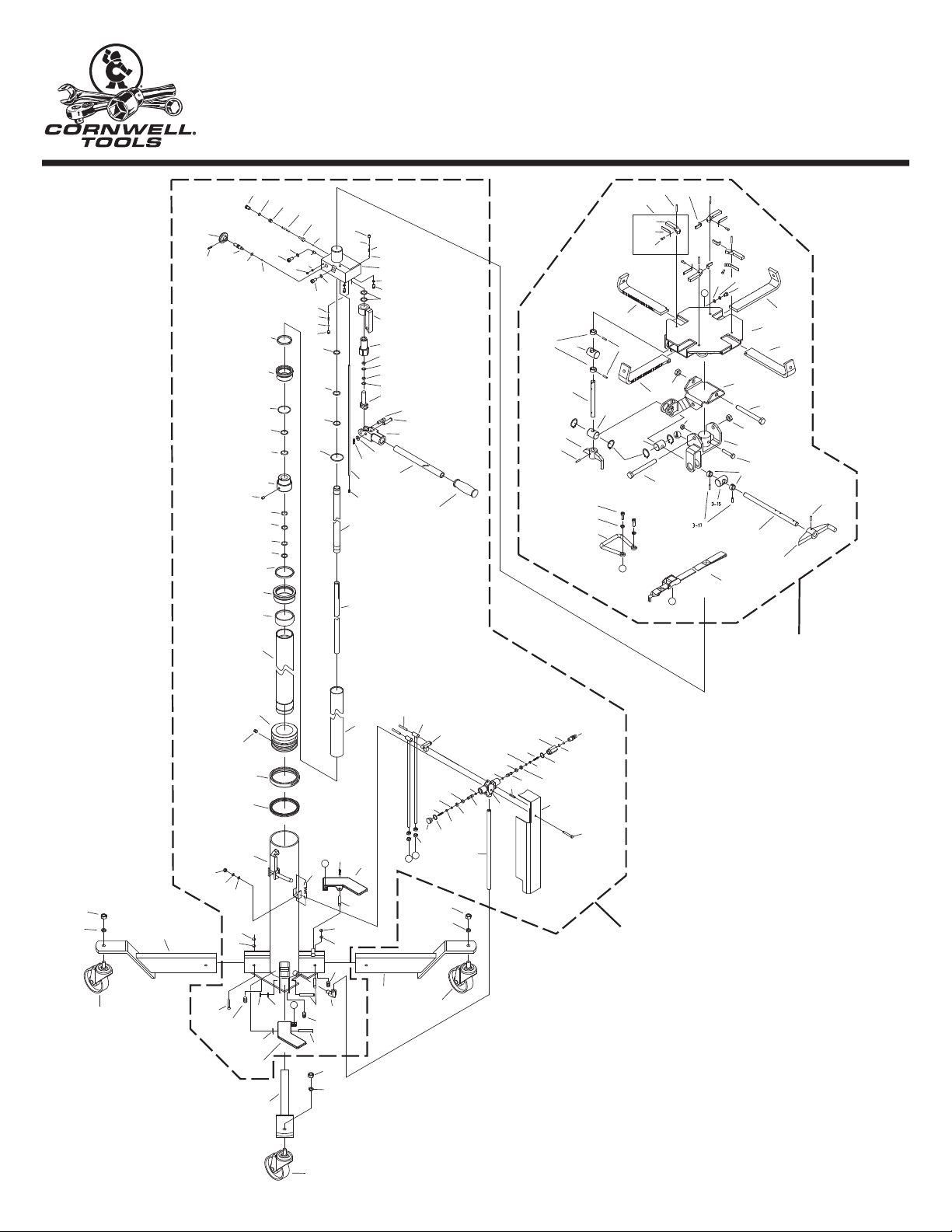
Please refer to the exploded view drawing on page 5 in this manual in order to identify parts:
1. Place the hydraulic power unit horizontally on a bench. Secure the legs (#2-4) in the receivers in the bottom of the cylinder (#1-1A)
with the bolts (#2-5), washers (#2-6) and nuts (#1-29). Do not tighten.
2. Install the set screw (#1-85) at the bottom of each leg receiver so the legs are firmly seated in the receivers.
3. Secure swivel casters (#2-1 and #2-7) to leg caster brackets as shown in the exploded view drawing on page 5 and place the jack upright
on the floor.
4. Tighten the hardware that secures the legs (#2-4) to the cylinder (#1-1A).
5. Place the saddle assembly on the stud protruding from the top of the hydraulic unit assembly, (CTJTJ1KAPUNIT). Align the hole in the
saddle with the hole in the stud and secure with the bolt (#3-26) and nut (#3-27).
6. Sometimes air gets trapped in the second stage hydraulic system during shipping and/or handling. Evidence of an air bound system is a
spongy feeling during the pump operation, or the ram will not rise to maximum extension, or the ram will not rise proportionate to a full
incremental pump stroke.
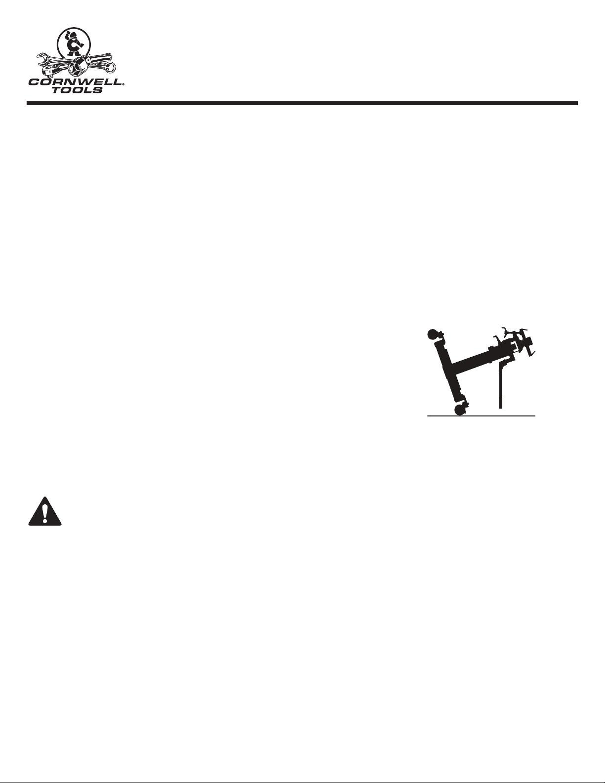
PURGING AIR FROM THE SECONDARY STAGE HYDRAULIC SYSTEM:
a. Turn the release valve knob in a clockwise rotation until it stops. Now turn the knob in a
counterclockwise direction two full rotations.
b. Tilt the entire jack on two caster wheels with the pump handle pointing down as shown in
the accompanying silhouette. At the same time, operate the pump handle until the loose feel
of the pump is met with some resistance.
c. Turn the release valve knob in a clockwise rotation until it stops and at the same time continue
pumping the handle while lifting the jack to its upright position.
d. Pump the jack to maximum extension. Repeat steps "a" through "c" until all air is purged
from the system.
7. The primary stage of the power unit is air activated. The air activated portion will also give the user many years of trouble free operation
if the shop air system is properly maintained. The shop air system must have an air regulator adjusted to the proper pressure. The system
must be free from dirt and moisture. Do not drop disconnected air lines on dirty shop floor or dirty environment and then reconnect to the
jack. Contaminants in the air system can cause the air valve to malfunction and the air cylinder to score. Contaminants and/or water
found in the air cylinder voids the warranty.
OPERATION
This is the safety alert symbol used for the OPERATING INSTRUCTIONS section of this manual to alert you to potential personal
injury hazards. Obey all instructions to avoid possible injury or death. IMPORTANT: Before attempting to raise any vehicle, check
vehicle service manual for recommended lifting surfaces.
1. Lift the vehicle to the desired work height and support the vehicle in accordance with the lift manufacturer's recommended support
procedure and all the instructions and warnings in this manual.
2. Use an under hoist stand rated greater than the weight of the engine to support the engine before unbolting the transmission from the
engine or bolting the transmission to the engine.
3. Position the transmission jack directly under the transmission. Depress the foot pedal marked "UP" to raise the jack to maximum first
stage height. Pump the handle on the hydraulic second stage in order to raise the saddle to a height very close to the center of balance
point of the transmission oil pan but do not touch the transmission. IMPORTANT: When applying a load to the jack's saddle, the jack's
air stage ram should be either lowered all the way down or extended all the way up and in its pressurized locked position. If a load is
applied to the jack's saddle when the first stage air ram is only partially raised, the jack's ram may drop suddenly.
4. Adjust the ratchet arms on the saddle so that the bent up section of the arms will fit in the mounting flange around the perimeter of the
transmission oil pan. Slowly and gently pump the jack so the connection is made and then secure the transmission to the jack's saddle
with the tie down strap provided. Sometimes it is necessary to turn the fore and aft and also the side to side tilt knobs so the saddle is
in the proper alignment with the transmission pan before securing the load to the saddle.
5. Make sure the tie down strap is very tight when securing the transmission to the saddle and before raising or lowering the transmission.
6. Remove the transmission from the engine according to instructions in the vehicle service manual.
7. Once the transmission has been disconnected from the engine, very slowly turn the release valve knob on the second stage hydraulic
block in a counter clockwise direction. Make sure the jack's saddle and transmission do not hang up on any under car components,
wiring, fuel lines, etc.
IMPORTANT: Continue to lower the load until the second stage bottoms out and then depress the first stage "UP" pedal for a second to increase
air pressure before depressing the "DOWN" pedal to lower the transmission all the way down.
8. When installing a transmission, follow the above instructions but in the applicable order and according to the vehicle manufacturer's
installation procedure.
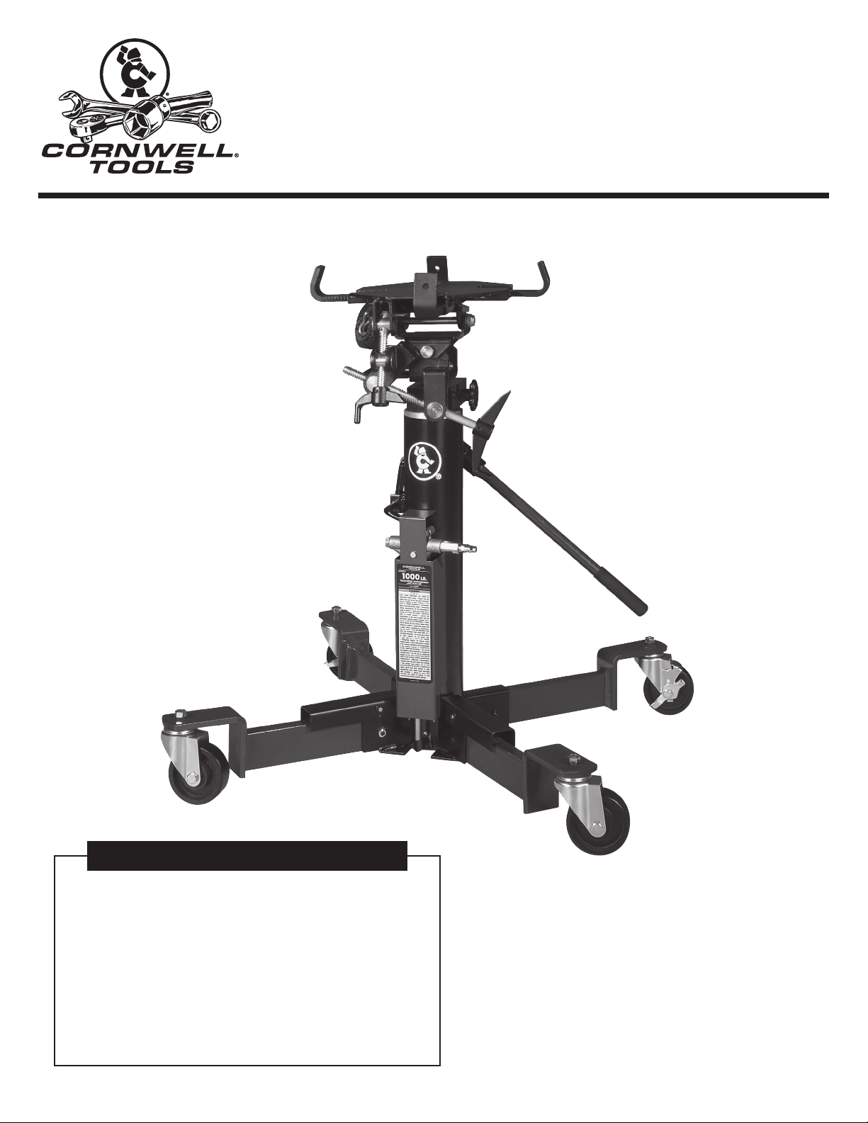
CTJTJ1KA
1,000 Lb. Telescoping Transmission
Jack with Air

-Save these instructions-
PREVENTATIVE MAINTENANCE
This is the safety alert symbol used for the PREVENTATIVE MAINTENANCE section of this manual to alert you to potential
personal injury hazards. Obey all instructions to avoid possible injury or death.
1. Always store the jack in a well protected area where it will not be exposed to inclement weather, corrosive vapors, abrasive dust, or any
other harmful elements. The jack must be cleaned of water, snow, sand, grit, oil, grease or other foreign matter before using.
2. Lubricate moving parts, excluding the telescopic rams, monthly with a general purpose grease.
IMPORTANT: any jack found to be defective as a result of worn parts due to insufficient or lack of lubrication is not eligible for warranty
consideration.
3. It should not be necessary to refill or top off the reservoir with hydraulic fluid unless there is an external leak. An external leak requires
immediate repair which must be performed in a dirt-free environment by qualified hydraulic repair personnel who are familiar with this
equipment.
IMPORTANT: In order to prevent seal damage and jack failure, never use alcohol, hydraulic brake fluid or transmission oil in the jack. Use Chevron
Hydraulic Oil AW ISO 32, its equivalent Unocal Unax AW 150 or hydraulic jack oil.
4. Every jack owner is responsible for keeping the jack labels clean and readable. Use a mild soap solution to wash external surfaces of
the jack but not any moving hydraulic components.
5. Do not attempt to make any hydraulic repairs unless you are a qualified hydraulic repair person that is familiar with this equipment.
Repairs must be performed by an authorized service center.
PROPER STORAGE
It is recommended that the jack be stored in a dry location with all wheels touching the ground on a relatively level surface.
TROUBLESHOOTING
PROBLEM ACTION
1. Unit will not lift rated load. Purge air from hydraulic system by following procedure under
SETUP.
2. Unit will not sustain rated load or feels “spongy” under rated load. Purge air from hydraulic system as above.
3. Unit will not lift to full height. Purge air from hydraulic system as above.
4. Handle tends to raise up while the unit is under rated load. Pump the handle rapidly several times to push oil past ball
valves in power unit.
5. Unit still does not operate. Contact Cornwell Customer Service.
WARRANTY COVERAGE
Cornwell Quality Tools Company (“Cornwell”) warrants against defects the hydraulic pump on this product for a period of TWO (2) YEARS from the
date of original retail purchase. Cornwell Quality Tools Company (“Cornwell”) warrants against defects the balance of components on this product
for a period of 90 days from the date of original retail purchase. Subject to the conditions and limitations set forth below, Cornwell will, at its option,
either repair or replace any part of the product(s) that proves defective by reason of improper workmanship or materials.
This warranty does not cover any damage to this product that results from accident, abuse, misuse, natural or personal disaster, or any unauthorized
disassembly, repair, or modification. Repairs, disassembly and modification are only authorized to be made by Cornwell or
a warranty service center approved by Cornwell.
WARRANTY SERVICE
To obtain warranty service, contact your Cornwell dealer.
EXCLUSIONS AND LIMITATIONS
THIS WARRANTY AND THE REMEDIES SET FORTH ABOVE ARE EXCLUSIVE AND IN LIEU OF ALL OTHER WARRANTIES, REMEDIES AND
CONDITIONS, WHETHER ORAL OR WRITTEN, EXPRESS OR IMPLIED. CORNWELL SPECIFICALLY DISCLAIMS ANY AND ALL IMPLIED
WARRANTIES, INCLUDING, TO THE EXTENT PERMITTED BY APPLICABLE LAW, ANY WARRANTIES OF MERCHANTABILITY AND FITNESS FOR
A PARTICULAR PURPOSE. IF CORNWELL CANNOT LAWFULLY DISCLAIM IMPLIED WARRANTIES UNDER THIS LIMITED WARRANTY, ALL SUCH
IMPLIED WARRANTIES ARE LIMITED IN DURATION TO THE DURATION OF THIS WARRANTY. IN NO EVENT SHALL CORNWELL BE LIABLE TO THE
PURCHASER OR TO THE USER OF A CORNWELL PRODUCT FOR ANY SPECIAL, INCIDENTAL OR CONSEQUENTIAL DAMAGES BASED UPON
BREACH OF WARRANTY, BREACH OF CONTRACT, NEGLIGENCE, TORT, OR ANY OTHER LEGAL THEORY. SUCH DAMAGES INCLUDE, WITHOUT
LIMITATION, EXPENSES, LOST REVENUES, LOST SAVINGS, LOST PROFITS, OR ANY OTHER INCIDENTAL OR CONSEQUENTIAL DAMAGES
ARISING FROM THE PURCHASE, USE OR INABILITY TO USE THE CORNWELL PRODUCT.
Some states do not allow the exclusion or limitation of incidental or consequential damages or exclusions or limitation on the duration of implied
warranties or conditions, so the above limitations or exclusions may not apply to you. This warranty gives you specific legal rights, and you may also
have other rights that vary by state.
Repair kits and replacement parts are available for many Cornwell products, regardless of whether or not the product is still covered by a warranty
plan.
CTJTJ1KA 4 03/23/20
CTJTJ1KA
1,000 Lb. Telescoping Transmission
Jack with Air

-Save these instructions-
1-67
1-66 1-65
1-64
1-63
1-84
1-83
1-87
1-62 1-61
1-60
1-56
1-59
1-58
1-57
1-55
2-3
2-2
2-4
2-7
1-29
1-29
1-29
1-5
1-9
1-3
1-8
1-3
1-2
1-5
1-85
C
C
D
D
B
B
A
1-85
1-85
1-4
2-4
2-7
2-2
2-3
2-5
2-6
2-6
2-6
2-4
2-3
2-2
2-1 2-5
3-17
3-15
3-11
3-22
3-13
3-18
3-16
3-26
3-9
3-21
3-19
3-8
3-16 3-15
3-10
3-12
3-18
3-17
3-14
3-14
3-31
3-20
3-30
3-29
3-28
3-2
3-21
3-27
3-5
3-5A
3-5B
3-5C
3-4
3-3
3-1
3-2
3-23
3-24
3-25
3-6 3-7
1-71
1-50
1-70
1-69
1-68
1-51
1-52
1-54
1-53
1-47
1-48
1-49
1-23
1-81
1-3
1-82
1-79
1-78
1-77
1-76
1-75
1-74
1-73
1-74
1-73
1-72
1-80
1-46
1-45
1-44
1-44
1-43
1-43
1-42
1-42
1-41
1-39
1-38
1-39
1-38
1-37
1-36
1-88
1-35
1-33
1-32
1-1A
1-7
1-69
1-6
1-34A
1-86
1-40
1-10
1-11
1-12
1-29
1-28 1-21
1-26
1-27
1-20
1-20
1-22 1-24 1-25
1-23
1-21
1-19
1-17
1-15
1-30
1-18
1-18
1-16
1-16
1-14
1-14
1-19
1-17
1-15 1-13
1-31
1-56
1-51
1-52
1-53
1-54
1-50
1-55
CTJTJ1KAPUNIT
Complete Replacement
Hydraulic Unit Assembly
RS1000SA
Complete
Saddle
Assembly
CTJTJ1KA 5 03/23/20
CTJTJ1KA
1,000 Lb. Telescoping Transmission
Jack with Air

-Save these instructions-
CTJTJ1KA
1,000 Lb. Telescoping Transmission
Jack with Air
CTJTJ1KA 6 03/23/20
1-1A Oil Cylinder Assembly 1
1-2 Coupler 1
1-3 Pin 3
1-4 Pedal A 1
1-5 Pin 2
1-6 Washer 1
1-7 Nut 1
1-8 Spring 1
1-9 Pedal B 1
1-10 Pin 2
1-11 Link Rod 2
1-12 Link Rod 1
1-13 RS7200B113A Valve Block (incl. #1-13 - 1-25, 1-28) 1
1-14 O-Ring 2
1-15 Valve Rod 2
1-16 Sealing Washer 2
1-17 Cap 2
1-18 Copper Washer 2
1-19 Screw 2
1-20 Spring 2
1-21 Copper Washer 2
1-22 Coupler 1
1-23 Filter 2
1-24 Snap Ring 1
1-25 Coupler 1
1-26 Plate 1
1-27 Bolt 1
1-28 Cap 1
1-29 Nut 8
1-30 Pin 1
1-31 RS7200C131 Air Pipe 1
1-32 * Y-Seal 1
1-33 Bushing 1
1-34 RS1000134 Piston 1
1-35 Pneumatic Piston Rod 1
1-36 Cylinder Cap 1
1-37 Guide Ring 1
1-38 * Nylon Gasket 2
1-39 * O-Ring 2
1-40 Screw 1
1-41 Screw Cap 1
1-42 * O-Ring 2
1-43 * Nylon Gasket 2
1-44 * O-Ring 2
1-45 Piston Cap 1
1-46 Guide Ring 1
1-47 Oil Container 1
1-48 Hydraulic Piston Rod 1
3-1 Bracket 1
3-2 RS7140C32BK Bracket C - Black 2
3-3 RS7140C33BK Bracket B - Black 1
3-4 RS7140C34BK Bracket A - Black 1
3-5 Retainer Plate Assembly 4
3-5A Retainer Plate 4
3-5B RS7140CSABK Spring Assy (incl. #3-5A - 3-5C, 3-6, 3-7) - Black 4
3-5C Rivet 4
3-6 Pin 4
3-7 Retainer Plate A 3
3-8 Adjusting Bracket 1
3-9 Adjusting Bracket A 1
3-10 RS1000310BK Screw A (incl. #3-10, 3-12, 3-18) Rev. B - Black 1
3-11 RS1000311BK Screw B (incl. #3-11, 3-13, 3-18) Rev. B - Black 1
3-12 Handle B 1
3-13 Handle A 1
3-14 *** Shaft 2
Item No. Part No. Description Qty.
1-49 Oil Cylinder 1
1-50 * Copper Washer 3
1-51 * Steel Ball 2
1-52 Spring 2
1-53 Steel Ball 2
1-54 Screw 2
1-55 * Copper Washer 2
1-56 Bolt 2
1-57 * Steel Ball 1
1-58 * Ball Seat 1
1-59 * Spring 1
1-60 Screw 1
1-61 Washer 1
1-62 Bolt 1
1-63 * Steel Ball 1
1-64 * O-Ring 1
1-65 RS7200B165 Oil Release Valve Rod (incl. #1-64 - 1-67) 1
1-66 Pin 1
1-67 Release Knob 1
1-68 RS1000168BK Valve Block Assembly - Black 1
1-69 Lock Washer 3
1-70 Bolt 2
1-71 RS7200B171BK Pump Seat - Black 1
1-72 RS7200B172BK Pump Cylinder - Black 1
1-73 * O-Ring 2
1-74 * Snap Ring 2
1-75 RS7200B175 Pump Plunger 1
1-76 Pin 1
1-77 Pin 1
1-78 RS7200B178BK Handle Socket (incl. #1-76 - 1-78, 1-3) - Black 1
1-79 RS7200B179BL Handle (incl. #1-79, 1-80) - Blue 1
1-80 Handle Sleeve 1
1-81 Oil Pipe 1
1-82 Washer 1
1-83 Washer 1
1-84 Bolt 1
1-85 Bolt 4
1-86 Bolt 1
1-87 * Throttle Valve 1
1-88 Bushing 1
2-1 RS7140C21 Non-Locking Swivel Caster (incl. #2-1 - 2-3) 2
2-2 Lock Washer 4
2-3 Nut 4
2-4 Leg 4
2-5 Bolt 4
2-6 Lock Washer 4
2-7 RS7140C22 Locking Swivel Caster (incl. #2-2, 2-3, 2-7) 2
RSCTJTJ1KAPLK Product Label Kit (not shown) 1
3-15 *** Shaft 2
3-16 *** Bushing 4
3-17 Pin 4
3-18 Pin 2
3-19 Bolt 1
3-20 Bolt 1
3-21 Lock Nut 2
3-22 RS7140C322 Strap 1
3-23 Bolt 1
3-24 Lock Washer 1
3-25 Washer 1
3-26 ** Bolt 1
3-27 ** Lock Nut 1
3-28 Grip 1
3-29 Washer 2
3-30 Bolt 2
3-31 Snap Ring 4
Only items identified by part number are available for purchase.
* Only available in Seal Kit, RS7200DSK, ** Only available in Bolt Kit, RS7140CBK, *** Only available in Saddle Bearing Kit, RS7140SBK. (2 each of #3-14, #3-15, 4 each of #3-16, #3-17).
PARTS LIST FOR SADDLE ASSEMBLY
Table of contents
Other Cornwell Tools Jack manuals

Cornwell Tools
Cornwell Tools CTJTRJ22T User manual

Cornwell Tools
Cornwell Tools CSEFJ350BK-BL User manual

Cornwell Tools
Cornwell Tools CTJ35BK User manual

Cornwell Tools
Cornwell Tools CTJLP2NG User manual

Cornwell Tools
Cornwell Tools CSEVS22T User manual

Cornwell Tools
Cornwell Tools CSESJ350A User manual

Cornwell Tools
Cornwell Tools CTJHW35BL User manual

Cornwell Tools
Cornwell Tools CTJ35NG User manual

Cornwell Tools
Cornwell Tools CSETJ1000 User manual

Cornwell Tools
Cornwell Tools CSEVS6TBL User manual