V-3
31 31
31
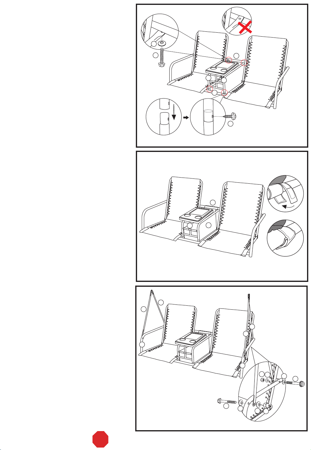
Step 15:
Hook the suspension springs (#31) into the top
of both holes of the swing arm tubes (#15).
Repeat the same procedure for both sides.
See Fig. H.
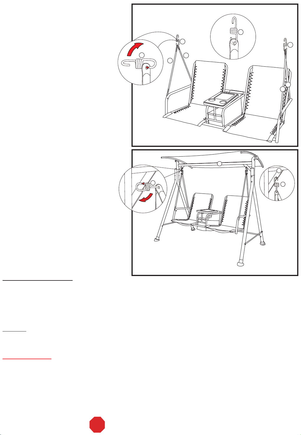
Step 16:
Hang the opposite ends of the suspension
springs (#31) into the holes located on the
angled braces of the top cross beam
w/adjustable teeth (#1). Repeat the same
procedure for both sides. See Fig. I.
To assure stability, double check that all of
the bolts have been completely tightened.
PAGE 7 OF 8
Fig. H
Fig. I
31
15
15
15 15
1
31
31
Special Warnings
1. The user of this swing should always inspect it before each use.
2. It is essential to place this swing on level ground and not less than 6 feet away from any obstruction, such as
fences, garages, houses, overhanging branches, laundry lines, or electrical wires.
3. Check the tightness of all of the nuts and bolts on a regular basis.
4. Make sure that the suspension springs are properly secured before each use.
5. Always remove the canopy in heavy wind conditions; otherwise the swing may tip over and cause damage to
its parts.
6. The manufacturer will not accept responsibility for unauthorized repairs or modifications to the swing or its parts.
7. Oil all of the metal parts that move regularly.
8. Weight limit is 700 lbs.
Cleaning and Maintenance
• Wash frame and fabric parts with mild soap and water, rinse thoroughly, and dry completely. Do not use
bleach, acid, or other solvents on the frame or fabric parts.
• We recommend the use of furniture covers when not in use.
• Inspect and tighten all bolts and fasteners on a regular basis to ensure the proper performance and safety of
your swing.
• In order to prolong the life and beauty of your swing, we recommend that it be stored in a dry and protected area
during off season periods.
Warning:
Make sure that both ends of the suspension
springs (#31) go completely through the holes
in the angled braces on the top cross beam
w/adjustable teeth (#1) and the swing arm
tubes (#15).
1
Warranty
•This product is covered by Courtyard Creations Inc.’s one–year limited warranty.
•Proof of purchase (dated register receipt) is required for warranty claims.
•It remains the customer’s responsibility for freight and packing charges to and from the service center.
STOP DO NOT RETURN TO THE STORE!