CPS Pro-Set TRA21 Series User manual

GENERAL INFORMATION
2
Congratulations on your purchase of the all new Pro-Set
® TRA21 Series Mobile A/C
refrigerant recovery unit. The TRA21 can be setup for either R-134a or R-1234yf operation.
The TRA21 utilizes CPS’s patent pending 2 cylinder oil-less compressor. The unit is
equipped with a suction side oil separator to collect oil removed from the mobile A/C
system. The unit also is equipped with a suction side filter drier with moisture sightglass.
Features:
• Convertible for Mobile A/C R-134a and R-1234yf systems
• Convertible for Commercial recovery
• Small High Side volume eliminates pump down system
• Fast and easy convertible instructions
• All components mounted on a heavy duty roll cage
• Easy to carry handle integrated into the roll cage
• Models TRA21, TRA21C and TRA21S include tank overfill sensor cord
• High Pressure cutout switch
This manual contains important information on the proper procedures for operating
this equipment. Please pay close attention to the: Safety Information, Warnings, and
Cautions provided throughout this manual.
ALWAYS REMEMBER “ SAFETY FIRST ”
Table of Contents
Introduction
General Information 2-5
Introduction 2
General Safety Instructions 3
Specifications 4
Unit Layout 5
6-11
6-7
Operation
Direct Vapor or Liquid Recovery
Liquid Flush Recovery
Filter Drier Maintenance
Trouble Shooting Chart
8-9
10
11

GENERAL INFORMATION
3
General Safety Instructions
ONLY QUALIFIED SERVICE PERSONNEL SHOULD OPERATE THIS UNIT. SOME COUN-
TRIES MAY REQUIRE THE USER TO BE LICENSED. PLEASE CHECK WITH YOUR LOCAL
GOVERNMENT AGENCY.
This equipment has been certified by Intertek to meet SAE J2810 for R-134a
This equipment has been designed to meet SAE J2851 for R-1234yf
CAUTION: R-1234yf is a Class A2 flammable refrigerant. Do not recover other
flammable besides R-1234yf. Minimize leakage when recovering these refrigerants.
USE IN A WELL VENTILATED AREA.
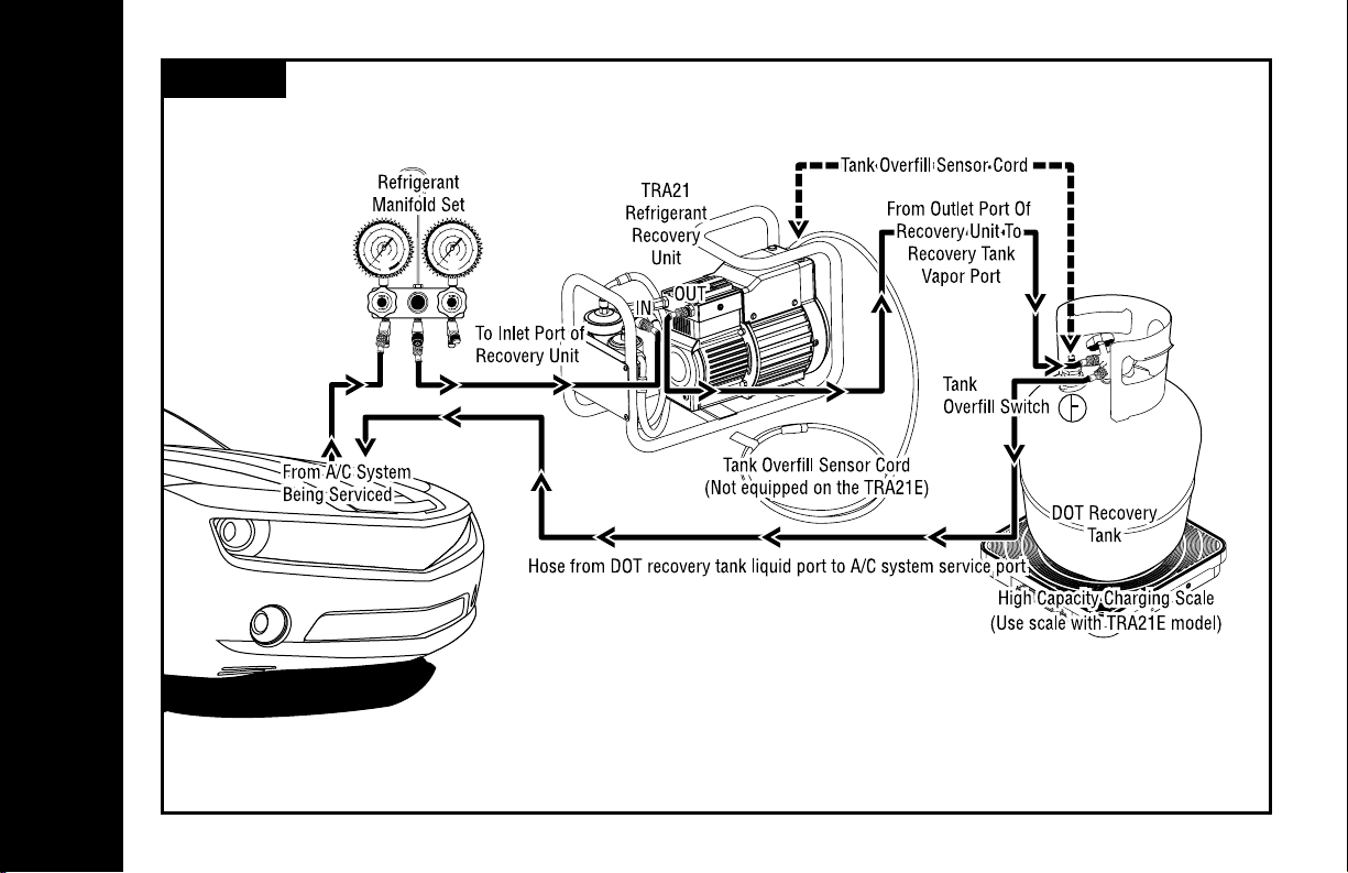
DANGER - The recovery tank used with this
unit contains liquid refrigerant. Overfilling
of the recovery tank may cause a violent
explosion resulting in severe injury or
even death. As a minimum, use a scale to
continuously monitor the recovery tank
weight.
DANGER - Avoid breathing refrigerant vapors
and lubricant vapor or mist. Breathing
high concentration levels may cause heart
arrhythmia, loss of consciousness, or even
cause suffocation.
DANGER - ELECTRICAL SHOCK
HAZARD - Always disconnect power
source when servicing this equipment.
DANGER - EXPLOSION RISK - Do not
recover flamable refrigerants.
CAUTION - All hoses may contain liquid
refrigerant under pressure. Contact with
refrigerant may cause frostbite or other
related injuries.
Wear proper personal protective equipment
such as safety goggles and gloves. When
disconnecting any hose, please use extreme
caution.
CAUTION - Avoid breathing refrigerant
vapors and/lubricant mist. Exposure
may irritate eyes, nose, throat and skin.
Please read the manufacturers Material
Safety Data Sheet for further safety
information on refrigerants and lubricants.
CAUTION - To reduce the risk of fire,
avoid the use of extension cords thinner
than NO. 14 awg. (2,5mm2) to prevent the
overheating of this cord please keep length
to a minimum.
CAUTION - Do not use this equipment in
the vicinity of spilled or open containers of
gasoline or other flammable substances.
Make certain that all safety devices are
functioning property before operating the
equipment.

Model Number TRA21 TRA21C TRA21S TRA21E
Refrigerants Automotive: R-134a, R-1234yf Commercial: ARI740 Groups III, IV and V
Temperature Operating Range 32 ˚F - 120 ˚F (0 ˚C - 49 ˚C)
Power Source 115VAC 60Hz 1Ph 220-240VAC 50Hz 1Ph
Maximum Power Consumption 1000 W
Inlet Filter Drier with Moisture Indicator 16 Cubic Inch Drier
Motor Protection Thermal Overload
High Pressure Shut-Off (PSI) 550 450 550 525 Manual (36.2 bar)
Exterior Protection Painted steel tubular roll cage frame.
Contents Included TRA21 TRA21C TRA21S TRA21E
R-134a Manifold Hose Set Included Included Included
30 lb DOT Recovery with Overfill Sensor Included Included Included
Overfill Sensor Cord Included Included Included
Suction Hose Included
Discharge Hose Included Included Included Included
Oil Drain Bottle and Hose Included Included Included Included
R-1234yf Low Side Coupler Included
R-134a Low Side Coupler Included
1/2" ACME x 1/4" SAE Female Adaptor Included Included Included
Dimensions 17.5" (444mm) Long x 11.25" (285mm) High x 7.75" (196mm) Wide
Weight 32.2 lb / 14.6 kg
TRA21O, TRA21CO and TRA21SO are base units which only include an Oil Drain Bottle and Hose.
GENERAL INFORMATION

GENERAL INFORMATION
5
TRA21 Unit Layout
1 - Inlet port
2 - Oil drain valve and port
3 - Base unit
4 - High pressure indicator light
5 - Overfill sensor cord and indicator light (not included on the TRA21E)
6 - Roll cage handle
7 - Discharge Port
8 - Oil seperator
9 - Drier with moisture indicator
6
5
5
4
3
7
9
8
2
1

OPERATION
6
Direct Vapor or Liquid Recovery
IMPORTANT: Before starting the recover of the refrigerant, a refrigerant identifier should
be used to determine the type and purity of the refrigerant. Failure to properly identify
the refrigerant could potentially expose the user to danger from flammable refrigerants
and health hazards from toxic refrigerants. Cross contamination of refrigerants can also
occur and would require special handling of the refrigerant.
1. Connect the TRA21 to mobile A/C using a manifold set. Use R-134a type manifold
(MAIA6Q) for R-134a system recovery. Use R-1234yf type manifold (MTHFO) for
R-1234yf system recovery. Use commercial type manifold (MBHP6) for commercial
refrigerant recovery.
2. Connect the TRA21 discharge to vapor port of the DOT recovery tank.
3. Connect the Yellow Overfill Sensor Cord to the float in the recovery tank. This cord
is not inclueded on the model TRA21E. For the TRA21E, use scale to monitor tank
weight. All connections should be done as shown in Diagram - 1.
4. Open the vapor valve on the recovery tank.
5. Start unit by pushing main power switch to the “ON” position.
6. Open the HI and LO side manifold valves to start the refrigerant flow.
7. Monitor the LO side manifold gauge. Once the gauge reaches 20˝ HG vacuum, turn
the unit off.
8. Close the vapor valve on the recovery tank.
9. Disconnect the hose from the TRA21 discharge, then a small amount of refrigerant
under pressure will be released.
10. Drain and measure oil from the oil separator. Only new lubricant, as identified by
the system manufacturer, should be replaced in the mobile A/C system. Removed
lubricant from the system and/or the equipment shall be disposed of in accordance
with the applicable federal, state and local procedures and regulations.

OPERATION
Diagram - 1

OPERATION
8
Liquid Flush
1. Connect the TRA21 to mobile A/C system LO side service port using the LO side of a
manifold. Do not connect the HI side of the manifold to the mobile A/C system. Keep
HI manifold valve closed throughout this process.
2. Connect the TRA21 discharge to the Vapor Port of the recovery tank. Recovery tank
should have at least 4 times the mobile system refrigerant charge.
3. Connect the Liquid Port of the recovery tank to the HI side service port of the mobile
A/C system. The user will need to provide this hose / coupler assembly.
4. Connect the Yellow Overfill Sensor Cord to the float in the recovery tank. This cord
is not included on the model TRA21E. For the TRA21E, use scale to monitor tank
weight. All connections should be done as shown in Diagram - 2.
5. Open the vapor valve on the recovery tank.
6. Start unit by pushing main power switch to the “ON” position.
7. Open the HI and LO side manifold valves to start the refrigerant flow.
8. Run for 15 minutes to allow liquid refrigerant to flood the mobile A/C system. The
liquid refrigerant will absorb the oil in the A/C system.
9. After 15 minutes, close the liquid valve on the recovery tank.
10. Monitor the LO side manifold gauge. Once the gauge reaches 20˝ HG vacuum, turn
the unit off.
11. Close vapor valve on the recovery tank.
12. Disconnect the hose from the TRA21 discharge, then a small amount of refrigerant
under pressure will be released.

Diagram - 2
OPERATION

Interconnecting Hoses, Service Hoses, Manifold and Service Coupler Maintenance:
The TRA21 uses brass to brass seal type fittings on the ends of the interconnection hose
assemblies. No hose gasket maintenance is required on the brass to brass type connections.
Periodically inspect the refrigerant hose assemblies, service hoses, manifold and service
coupler inner o-rings for excessive wear. Replace the compenent(s) if required. Periodically
leak check all hose connection points, hose ball valves, manifolds and service couplers.
Since this unit does pull a vacuum in the recovery process, excessive Non-Condensable
Gases (NCG’s) could be sucked into the system and placed in the storage tank.
Liquid filter drier manitenance: The TRA21 is equipped with a 16 cubic inch filter drier with
an integrated moisture indicator. This filter should be checked and replaced periodically.
This filter drier removes any moisture that may be contained in the recovered refrigerant.
Replace the filter drier as follows:
Caution: Always assume the presence of
high refrigerant when removing the filter
drier.
1. Remove filter drier by loosening the brass
flare nuts on each of the fliter drier. Pull
filter drier out of the spring clip holders.
2. Install new filter drier (ARXF2). Make sure
arrow points to the right as in Figure - 1.
3. Tighten brass flare nut into each end of
the new filter drier.
4. Check for leaks.
FILTER DRIER REPLACEMENT IS NOW COMPLETE
OPERATION
10
Routine Filter Maintenance
Figure - 1

OPERATION
Trouble Shooting Chart
Problem: The unit will only pull down to 0 pressure or a slight vacuum.
Solution: Check all LO side connections for possible leaks. If problem persists,
check vacuum level directly on the compressor inlet port.
Solution:
Check pressure differential at 400 PSIG discharge pressure. At 400 PSIG,
the unit should pull a minimum of a 5” hg. vacuum. If compressor looses
its capability of meeting this differential, the compressor seals may need
to be replaced.
Problem: HP Red LED lights up, unit starts for a few minutes then shuts off.
Solution:
The high pressure switch has activated. Make sure the discharge valve
and recovery tank valve(s) are open. Check for any other restrictions on
the discharge port of the unit. Correct restriction. Restart the unit.
Problem: TOS Red LED lights up and the unit shuts off or will not start.
Solution:
1. Check to make sure TOS cord is properly plugged into the recovery
tank float.
2. Check tank weight to verify that the tank is full. Empty or replaced tank.
Problem: The unit recovers at a very slow pace.
Solution:
Check for restrictions on the suction side connections. Make sure manifold
valves are open. Overtighted hose connections can collapse the rubber
gaskets causing a restriction.
Learn more about automotive A/C tools and equipment we have.
This manual suits for next models
4
Table of contents
Other CPS Test Equipment manuals

CPS
CPS AR2700 Series User manual

CPS
CPS BlackMax TR700 Series User manual

CPS
CPS FA1000 SERIES User manual

CPS
CPS Pro-Set TR600 Series User manual

CPS
CPS Pro-Set TR21C User manual

CPS
CPS AC-PLC KIT-800V/US User manual

CPS
CPS BlackMax TR700C User manual

CPS
CPS CR500 Series User manual

CPS
CPS Pro-Set TR600A Series User manual
Popular Test Equipment manuals by other brands

Tektronix
Tektronix 067-1002-99 instruction manual

Alcolizer
Alcolizer EC Calibration Station Service instructions

Honeywell
Honeywell MicroDock II operating manual

Dage
Dage 4000 Series Operator's guide

Psiber Data Systems
Psiber Data Systems Pinger Plus Network IP Tester user guide

MAST
MAST Keystone View VS-V 1155 instruction manual