ASSEMBLETHESAWGAGES
See Figure 4.
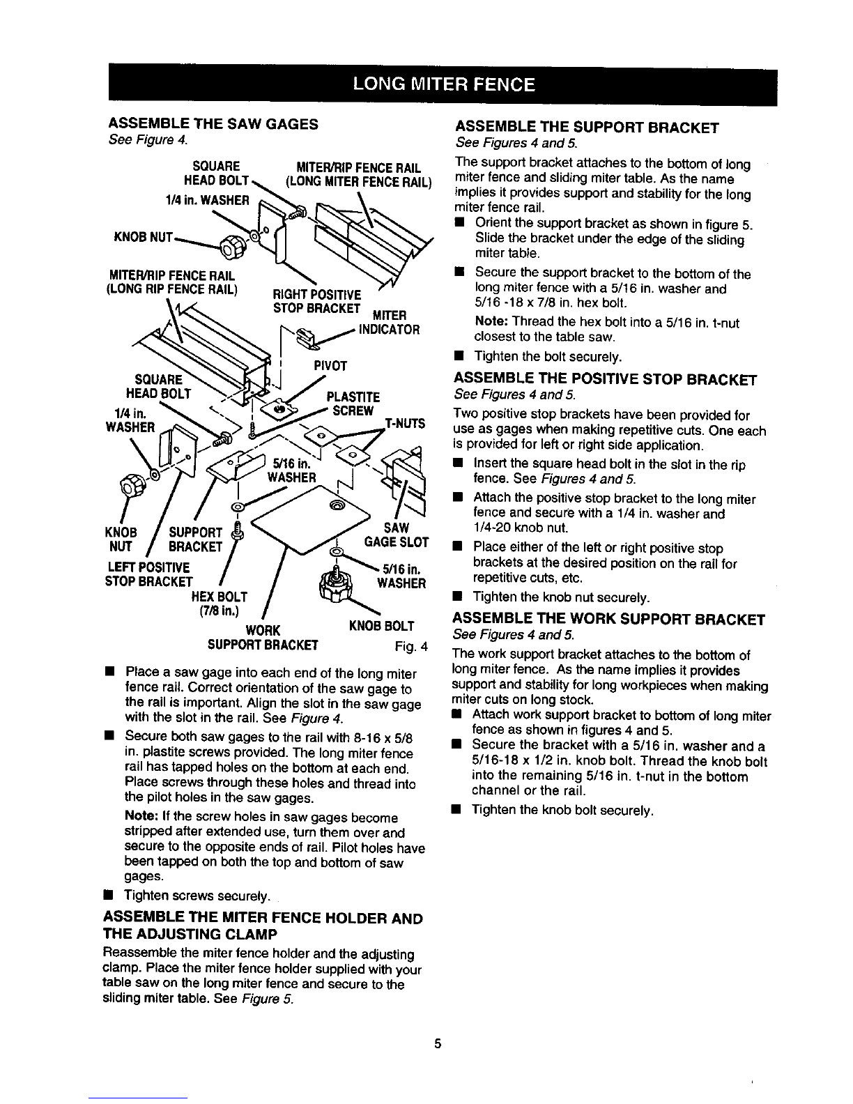
SOUARE MITER/RIPFENCERAIL
HEADBOLT_ (LONGMITERFENCERAIL)
1/4in.WASHER_,_ _., \
MITER/RIPFENCERAIL _
(LONGRIPFENCERAIL) RIGHTPOSITIVE
STOPBRACKET MITER
_._,_ INDICATOR
PIVOT
SOUARI
HEADBOLT PLAS_TE
l_in. SCREW
WASHER T-NUTS
t
KNOB SUPPORT SAW
NUT BRACKET/ GAGESLOT
LEFTPOSITIVE /
STOPBRACKET /WASHER
HEXBOLT
(7/8in.) WORK KNOBBOLT
SUPPORTBRACKET Fig. 4
•Place a saw gage intoeach end of the long miter
fence rail. Correct orientation ofthe saw gage to
the rail is important. Align the slot in the saw gage
with the slot in the rail. See Figure 4.
• Secure both saw gages to the rail with 8-16 x 5/8
in. plastite screwsprovided. The long miter fence
rail has tapped holes on the bottom at each end.
Place screws through these holes and thread into
the pilot holes in the saw gages.
Note: If the screw holes in saw gages become
strippedafter extended use, turn them over and
secure to the opposite ends of rail. Pilot holes have
been tapped on both the top and bottom of saw
gages.
• Tighten screws securely.
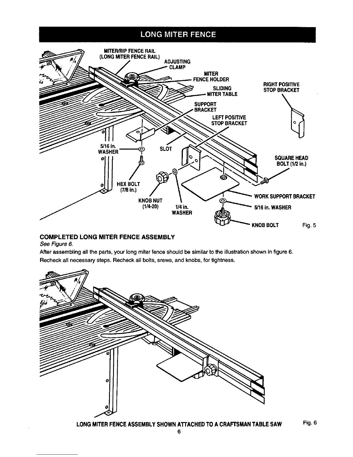
ASSEMBLE THE MITER FENCE HOLDER AND
THE ADJUSTING CLAMP
Reassemble the miterfence holderand the adjusting
clamp. Place the miter fence holdersuppliedwithyour
table saw on the long miterfence and secure to the
slidingmiter table, See Figure 5.
ASSEMBLE THE SUPPORT BRACKET
See Figures4 and 5.
The supportbracket attaches to the bottom of long
miter fence and slidingmitertable. As the name
impliesit provides support and stability for the long
miter fence rail.
• Orient the support bracket as shown in figure 5.
Slide the bracket under the edge of the sliding
miter table.
• Secure the supportbracket to the bottom of the
longmiter fence witha5/16 in.washer and
5/16 -18 x 7/8 in. hex bolt.
Note: Thread the hex bolt into a 5/16 in. t-nut
closest to the table saw.
• Tighten the bolt securely.
ASSEMBLE THE POSITIVE STOP BRACKET
See Figures 4 and 5.
Two positivestop brackets have been providedfor
use as gages when making repetitivecuts, One each
is providedfor left or rightside application,
•tnsert the squarehead boStinthe slotin the rip
fence. See Figures 4 and5.
• Attach the positive stop bracket to the long miter
fence and secure with a 1/4 in. washer and
1/4-20 knob nut.
• Place either of the leftor right positive stop
brackets at the desired position on the rail for
repetitive cuts, etc.
• Tighten the knob nut securely.
ASSEMBLE THE WORK SUPPORT BRACKET
See Figures4 and 5.
The work supportbracket attachesto the bottomof
longmiter fence. As the name implies itprovides
supportand stabilityfor longworkpieceswhen making
miter cutson longstock.
•Attachwork supportbracketto bottomof long miter
fenceas shownin figures4 and 5,
•Secure the bracket with a5/16 in. washer and a
5/16-18 x 1/2 in. knob bolt. Thread the knob bolt
into the remaining 5/16 in. t-nut in the bottom
channel or the rail.
•Tightenthe knob bolt securely.
5