Crane BevMAX Refresh 4 User manual


Page 2of 52

Page 3of 52
Table of Contents
CAUTIONS & WARNINGS.............................................................................................5
GENERAL INFORMATION ................................................................................................... 6
Vender Safety Precautions ..................................................................................................6
Product Identification..........................................................................................................6
CE Mark & IIA Declaration...................................................................................................6
Physical Characteristics .......................................................................................................6
INSTALLATION & SETUP ..................................................................................................... 7
Receiving Inspection............................................................................................................7
Unpacking the Vender.........................................................................................................7
Electrical Requirements.......................................................................................................7
Power Supply & Grounding Requirements .........................................................................8
Manual T-Handle Lock.........................................................................................................9
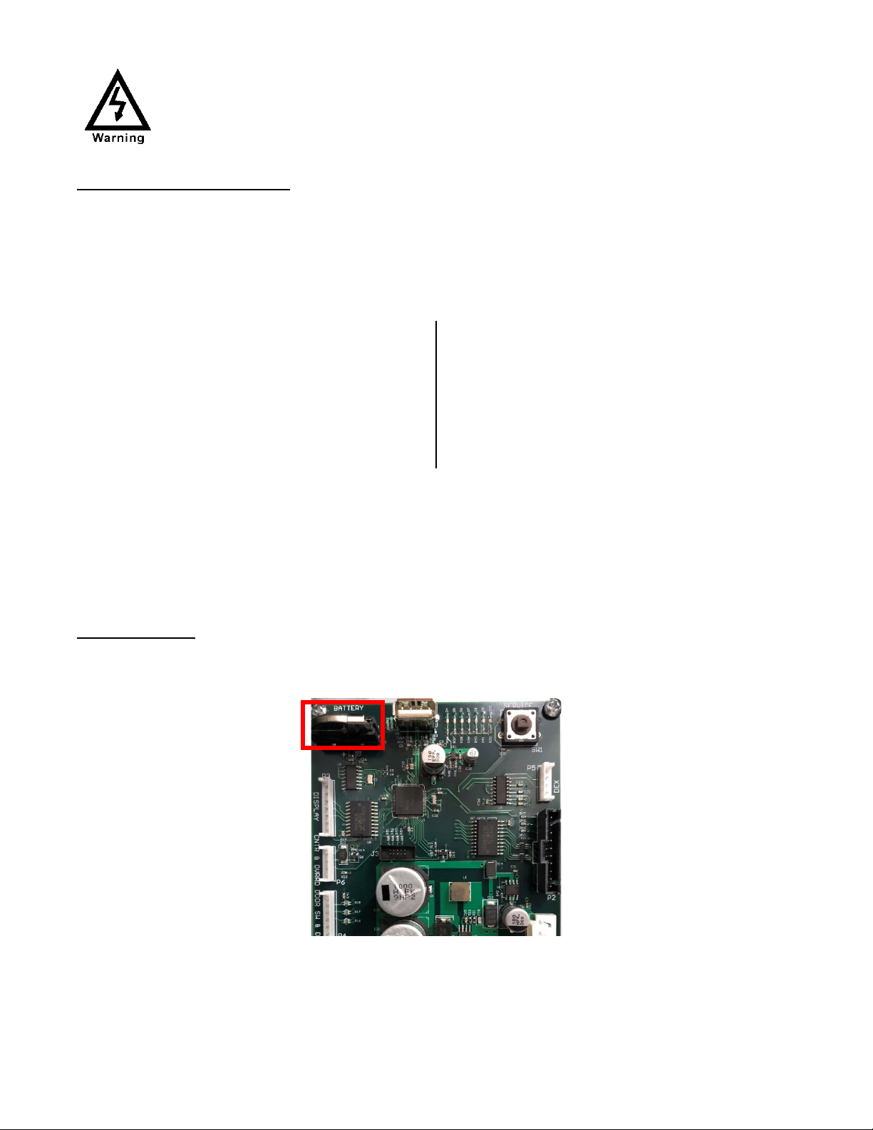
Service Note (Battery Back Up) ...........................................................................................9
Placing the Vender on Location.........................................................................................10
Acceptable Ambient Operating Temperature Range........................................................10
Level the Vender ...............................................................................................................10
Locate the Vender .............................................................................................................10
Install Price Labels .............................................................................................................11
Install Product ID Cards .....................................................................................................11
Coin Changers and Other Accessories...............................................................................11
Setting the Temperature Control......................................................................................11
Loading the Vender ...........................................................................................................12
Loading the Coin Changer Tubes.......................................................................................12
COMPONENTS ..........................................................................................................12
Omron Power Supply 24V 150W.......................................................................................12
AC Distribution Box ...........................................................................................................13
Vending Machine Controller & 5 Cabinet Peripheral Controllers.....................................13
Keypad...............................................................................................................................14
Digital Display ....................................................................................................................14
Delivery Port Assembly......................................................................................................14
Shelf / Tray Assembly ........................................................................................................15
Double Gate Assembly ......................................................................................................15
Slide / Pusher Assembly ....................................................................................................15
Delivery (Picker) Cup Assembly .........................................................................................15
X Axis (Horizontal) .............................................................................................................16
Y Axis (Vertical)..................................................................................................................16
Belt Tensioning Adjustment Components.........................................................................16
Refrigeration System .........................................................................................................16
Refrigeration Deck Clamp Assembly .................................................................................17
Wiring notes ......................................................................................................................17
PROGRAMMING ............................................................................................................... 18
General ..............................................................................................................................18
External Display Items .......................................................................................................18
Normal Operation Messages.............................................................................................18
Initial Programming...........................................................................................................18
Quick Reference Menu Items ...................................................................................21

Page 4of 52
MAJOR COMPONENT DESCRIPTION................................................................................ 22
AC Distribution Box ...........................................................................................................22
Omron Power Supply 24V 150W.......................................................................................22
Door Switch Bracket Assembly Switches...........................................................................22
GENERAL MAINTENANCE................................................................................................. 23
Power ................................................................................................................................23
Cleaning.............................................................................................................................23
VMC INSTALLATION ......................................................................................................... 25
VMCSOFTWARE UPDATE PROCEDURE .......................................................................... 25
VMC CONNECTIONS ........................................................................................................ 26
BEVMAX REFRESH 4 TROUBLESHOOTING....................................................................... 27
TROUBLESHOOTING DIAGNOSTIC LIGHTS..................................................................27
No Power to Vender..........................................................................................................28
No Vertical (Y) & No Horizontal (X) Movement.................................................................29
No Vertical (Y) Movement.................................................................................................31
No Horizontal (X) Movement ............................................................................................33
Cup Picker/Plunger will not Cycle & Eject an Item from the Gate Assy............................34
Port Door will not Open / Close ........................................................................................35
Port Door Stays Open, Display says “Please Remove Product” ........................................37
TROUBLESHOOTING TABLES......................................................................................38
Coin Acceptance Issues .....................................................................................................38
Bill Acceptance Issues........................................................................................................38
Vending Machine Controller (VMC) Issues........................................................................39
TROUBLESHOOTING FLOW CHARTS........................................................................... 40
All Coins Rejected Flow Chart............................................................................................40
All Bills Rejected Flow Chart..............................................................................................41
Incorrect Change Dispensed Flow Chart ...........................................................................42
Selection Will Not Vend Flow Chart ..................................................................................43
REFRIGERATION TROUBLESHOOTING FLOW CHARTS ...............................................................44
Ice / Frost on Evaporator Flow Chart ................................................................................44
Condensate on Outside of Product Door Flow Chart........................................................44
Compressor Will Not Stop Flow Chart...............................................................................44
Compressor Will Not Start Flow Chart ..............................................................................45
Machine Not Cooling Flow Chart ......................................................................................46
ELECTRICAL DIAGRAMS.................................................................................................... 47
BevMax Refresh 4 Classic Door Electronics Diagram (Domestic & Export) ......................47
BevMax Refresh 4 Classic AC Distribution Box Electronics Diagram (Domestic & Export)48
BevMax Refresh 4 Classic Port Assembly Electronics Diagram (Domestic & Export) .......49
BevMax Refresh 4 Classic XY Mechanism Electronics Diagram (Domestic & Export).......50
BevMax Refresh 4 Sequence of Operation. ......................................................................51
Notes. ................................................................................................................................52

Page 5of 52
Cautions & Warnings
High Voltage Warning / Electrical Warning Danger electricity, electric shock.
A Generic Warning.
Hazard Warning: Beware of moving machinery – Entanglement hazard.
Keep hands, loose clothing, and long hair away from moving parts.

Page 6of 52
GENERAL INFORMATION
VENDER SAFETY PRECAUTIONS
Please read this manual in its entirety. This service information is intended for use by a qualified service technician
who is familiar with proper and safe procedures to be followed when repairing, replacing or adjusting any Crane
Merchandising Systems vendor components. All repairs should be performed by a qualified service technician
who is equipped with the proper tools and replacement components, using genuine Crane Merchandising Systems
factory parts. This Vendor should only be used by those individuals that have a clear understanding of how to
operate a vending machine in a safe manner.
REPAIRS AND/OR SERVICING ATTEMPTED BY UNQUALIFIED PERSONS CAN RESULT IN
HAZARDS DEVELOPING DUE TO IMPROPER ASSEMBLY OR ADJUSTMENTS WHILE
PERFORMING SUCH REPAIRS. PERSONS NOT HAVING A PROPER BACKGROUND MAY
SUBJECT THEMSELVES TO THE RISK OF INJURY OR ELECTRICAL SHOCK WHICH CAN BE
SERIOUS OR EVEN FATAL.
PRODUCT IDENTIFICATION
First production of BevMax Refresh 4 5800-4/3800-4 Domestic and BevMax Refresh 4 5800-E4/3800-E4 Export
Venders with new electronics platform was May 2020. The production date of Crane Merchandising Systems
products is now determined by the date code incorporated in the serial number.
The Machine serial number incorporates the build date, in the format:
11yymmddxxxx
11 indicates the BevMax model, yymmdd is the year, month, & date of production, and xxxx is a sequential build
number.
CE Mark & IIA DECLARATION
An updated CE Mark or IIA Declaration document can be provided upon request: If needed please contact
Technical Support Manager in Williston, SC. Phone: 1- 803-266-5001 or email service@cranems.com.
PHYSICAL CHARACTERISTICS
BEVMAX REFRESH
5800-4
5800-E4
3800-4
3800-E4
HEIGHT 72” (182.88 cm) 72” (182.88 cm)
WIDTH 47” (119.38 cm) 39” (99.06 cm)
DEPTH CABINET 32” (81.28 cm) 32” (81.28 cm)
DEPTH WITH SERVICE
DOOR
33.5” (85.09 cm) 33.5” (85.09 cm)
BASE 3.5” (8.89 cm) 3.5” (8.89 cm)
SHIPPING WEIGHT
720 lbs.
(326.59 kg)
TBD lbs.
(TBD kg)
Noise Level Operates at < 70db.
Glass door width is 37.5” (95.25 cm) 5800’s, 28.1” (71.37 cm)
3800’s, height is 68” (172.72 cm) both.

Page 7of 52
INSTALLATION & SETUP
RECEIVING INSPECTION
DO NOT STORE THE VENDER OUTSIDE.
Upon receipt, inspect the Vender for any shipping damage. If there is any damage, have the delivery driver note
the damage on the bill of lading and notify Crane Merchandising Systems Customer Service. Although the terms
of sale are FOB shipping point, which requires the consignee to originate shipping damage claims, Crane
Merchandising Systems will gladly help if you must file a claim.
UNPACKING THE VENDER
Remove the stretch wrap, fiberboard edge protectors and corrugated front protector from the outside of Vender.
Do not store the Vender with stretch wrap on. Stretch wrap could bond
to the Vender’s surface, which could damage the finish.
Remove the shipping boards from the bottom of the Vender. The shipping boards are attached by the leveling
legs. To avoid unnecessary damage to the leveling legs or base, remove the shipping boards by using a 1-1/2 inch
or 38 mm socket type wrench to unscrew the leveling legs. Be sure to replace the legs after removing the shipping
boards. Once the skid boards are removed there is 3” (7.62 cm) from base flange to the floor with the leveling
legs screwed all the way in.
Once the Vender is unpacked, check the “B” Tray area for any additional parts, labels, or other information
concerning factory-equipped accessories such as Coin Mechanism, Bill Acceptor and Cashless Devices.
It is recommended the Vender be vend tested before shipping to the location. See INITIAL PROGRAMMING section
of this guide, “Test Mode”, # 9 “Test Vend”.
WARNING: TO AVOID THE POSSIBILITY OF A FIRE HAZARD, DO NOT STORE ANYTHING OR
ALLOW DEBRIS OF ANY KIND TO ACCUMULATE IN THE BOTTOM OF THE SERVICE AREA, IN
AND AROUND THE REFRIGERATION COMPARTMENT OF THE CABINET, OR IN FRONT OF THE
EVAPORATOR AND CONDENSER COILS.
WARNING: ENSURE THAT POWER IS DISCONNECTED FROM THE VENDER BEFORE
INSPECTING OR REPLACING LAMPS, OTHER ELECTRICAL COMPONENTS, OR WORKING
WITH OR ADJUSTING THE VENDING MECHANISM. FAILURE TO COMPLY WITH THESE
INSTRUCTIONS MAY SUBJECT THE USER TO THE RISK OF ELECTRICAL SHOCK OR
MECHANICAL INJURY, WHICH CAN BE SERIOUS OR FATAL.

Page 8of 52
ELECTRICAL REQUIREMENTS
Refer to the Machine serial number plate to determine the correct voltage and frequency.In the US and Canada
this is 120Vac, 60Hz, 1P. In Europe, Australia, and other export countries, this is 220/230/240Vac, 50Hz, 1P
depending upon your country voltage. The serial plate also specifies the ampere rating of the Machine. This
Machine must be plugged into a properly rated receptacle with its own circuit protection (fuse or circuit breaker).
Equipment Nominal Power Requirements -
120V / 10.2 A = *1224W (1.224kw)
220V / 5.8 A = *1276W (1.276kw)
240V / 5.8 A = *1392W (1.392kw)
*Note: Watts = V X A
POWER SUPPLY CORD and GROUNDING REQUIREMENTS
In accordance with the National Electrical Code and Underwriters Laboratories Inc., Domestic Vending Machines
are equipped with a three-wire Power Supply Cord and Ground Fault Circuit Interrupter (GFCI). The GFCI device
is provided as part of the Power Supply Cord and is either incorporated directly into the plug or mounted on the
cord adjacent to the plug.
WARNING
•The GFCI protects against current leakage caused by ground faults. The GFCI is not
designed to protect against over current or short circuits.
•DO NOT use the TEST and RESET buttons on the GFCI as an ON/OFF switch.
•The Vending Machine supply cord MUST be plugged directly into a properly
grounded, 3 wire receptacle that is properly protected by a fuse or circuit breaker. If
the receptacle will not accept the power cord plug, it must be replaced with a
properly grounded, 3 wire receptacle in accordance with the National Electrical Code
and Local Codes and Ordinances. The work should be done by a qualified electrician.
•DO NOT USE A 3 WIRE TO 2 WIRE ADAPTOR.
DO NOT REMOVE THE GROUND PIN ON THE PLUG OR IN ANY WAY BYPASS, MODIFY,
DEFEAT, OR DESTROY THE GROUNDING SYSTEM OF THE VENDING MACHINE.
DO NOT USE WITH AN EXTENSION CORD!
DO NOT REMOVE THE WARNING TAG ATTACHED TO THE POWER SUPPLY CORD.
The GFCI must be tested frequently and before each use in accordance with the instructions provided on the
GFCI device. IF THE GFCI DOES NOT PASS THE TEST, DO NOT USE THE MACHINE. Unplug the supply cord from
the receptacle and call the Crane Merchandising Systems Technical Support Group for assistance at 1-803-266-
5001.It is recommended that the Machine be located so that the GFCI device will be accessible after the
Machine is installed. After installation, visually inspect the GFCI and power supply cord to be sure it is not
crushed, pinched, or stretched. Protect the power supply cord during transportation and use. Periodically
inspect the power supply cord for damage. If the cord or plug is worn or damaged, it must be replaced with a
power supply cord of the same type, size and specification as originally provided with the Machine.
DO NOT USE THE VENDING MACHINE UNTIL THE WORN OR DAMAGED CORD IS REPLACED.

Page 9of 52
MANUAL T-HANDLE LOCK
Open the Service Door on the right side using the Key provided in the coin return cup, or if shipped with a locking
clip, remove the clip and install the lock. Ensure there is no power to the AC Distribution Box. On Venders with a
main power switch on the AC Distribution Box the switch needs to be in the OFF position. On Venders with a main
power quick disconnect plug on the AC Distribution Box the quick disconnect plug needs to be unplugged. Check
that all connectors are firmly seated on the Vending Machine Control Board (VMC) and at the various Cabinet
Peripheral Control Boards:
•Environmental Board
oRefrigeration control
oLighting control
•Port Board
oPort Motor
oPort Product Sensor
•Cup Motor Board
oCup Motor
oCup Product Sensor
•X Motor Board
oXMotor
•Y Motor Board
oYMotor
Retrieve the main power plug from the hole in the rear of the Vender and plug the cord in a properly grounded
120VAC, 15 Amp receptacle (U.S. and Canada). Open the Service Door and apply power to the AC Distribution
Box (if equipped with a Bill Acceptor, the Acceptor should cycle twice). The Display on the door will briefly show
the software version in use as “Software ###.## (i.e. 006r00) followed by the model number followed by the
default idle message “ENJOY A REFRESHING DRINK”, the LED Light Assemblies should be lit and the cooling unit
should start. If the Display shows “OUT OF SERVICE”, or the cooling unit fails to start, refer to the
TROUBLESHOOTING SECTION of this guide.
SERVICE NOTE
Battery Backup
The battery backup located on the VMC is used to maintain the date and time in case of power interruptions or
any time the main power is off.
FAILURE TO COMPLY WITH THESE INSTRUCTIONS MAY SUBJECT THE USER TO THE RISK OF
INJURY OR ELECTRICAL SHOCK WHICH CAN BE SERIOUS OR FATAL. PERIODICALLY INSPECT THE
POWER SUPPLY CORD FOR DAMAGE. IF THE CORD BECOMES DAMAGED IT MUST BE REPLACED
WITH THE SAME SIZE AND TYPE CORD. CONTACT CRANE MERCHANDISING SYSTEMS FOR
ASSISTANCE.

Page 10 of 52
PLACING THE VENDER ON LOCATION
!! CAUTION !!
DO NOT TRANSPORT THE VENDER TO OR FROM THE LOCATION
LOADED WITH PRODUCT OR DAMAGE TO THE VENDER MAY RESULT.
The Vender is intended for INDOOR USE ONLY. It should be kept out of direct sunlight and away from any heat
source. This Machine is not suitable for installation in an area where a water jet or hose and nozzle may be used.
The Vender must be on a solid, flat and level surface. Ensure the flooring can bear the weight load of a fully loaded
Vender (approximately 1109 lbs. or 503 kg). The Vender must be positioned close enough to an electrical outlet
so that an extension cord is not required. If the Machine will be subject to user misuse or vandalism, it is
recommended that the Vender be secured to the floor or wall as described in Crane Merchandising Systems
Technical Bulletin 344. Due to the large size and weight of the Vender, never attempt to move the Vender with a
Hand Truck or Stair Climber. Use a pallet jack or Vender/Cooler Dollies at all times when moving the Vender. The
Vender should never be slid or pushed in place. Never side load the leveling legs; doing so will cause damage to
the legs. Do not transport the Vender to or from customer locations loaded with product, as damage may result
due to excessive weight. Be sure to test Vender for proper operation before putting in to service on location. Call
the Crane Merchandising Systems Technical Service Department or your Crane Merchandising Systems
Representative for assistance.
ACCEPTABLE AMBIENT OPERATING TEMPERATURE RANGE
BevMax Refresh 4 Models 5800-4/3800-4 equipment manufactured by Crane Merchandising Systems is
designed to work properly in a temperature range of 75°F to 90°F (23°C to 32°C) in still air 65% R.H. non-
condensing.
LEVEL THE VENDER
Adjust the front leveling legs, ensuring that an even gap exists between the glass door and the top security angle
and receiver box, and then level the Machine front to rear. A carpenter’s level will help verify that the Vender is
level. Leveling legs are adjusted using a wrench or socket 1 ½” or 38 mm in size. If the Vender is to be used in a
bank of equipment, check the top and sides for proper alignment. If you are unable to properly level the Vender,
select an alternate location. NEVER PLACE OBJECTS UNDER THE LEVELING LEGS OF THE VENDER.
DANGER
THE VENDER MUST BE PROPERLY LOCATED AND LEVELED. IF THE MACHINE WILL BE
SUBJECT TO USER MISUSE OR VANDALISM IT IS RECOMMENDED THAT THE VENDER
BE SECURED TO THE FLOOR OR WALL AS DESCRIBED IN CRANE MERCHANDISING
SYSTEMS TECHNICAL BULLETIN 344 TO MINIMIZE THE RISK OF INJURY OR DEATH
FROM TIPPING. CALL THE CRANE MERCHANDISING SYSTEMS TECHNICAL SERVICE
DEPARTMENT OR YOUR CRANE MERCHANDISING SYSTEMS REPRESENTATIVE FOR
ASSISTANCE.
LOCATE THE VENDER
Do not block the rear of the Vender. Maintain a minimum of 4 inches (10 cm) from the wall to ensure adequate
airflow through the condenser and compressor. At the rear of the Vender, make sure nothing obstructs the air
exhaust at the back of the Machine.

Page 11 of 52
WARNING
TO AVOID THE POSSIBILITY OF A FIRE HAZARD, DO NOT STORE ANYTHING OR ALLOW
DEBRIS OF ANY KIND TO ACCUMULATE IN THE BOTTOM OF THE MACHINE, IN THE
BOTTOM OF THE SERVICE AREA, IN AND AROUND THE REFRIGERATION COMPARTMENT
OF THE CABINET, OR IN FRONT OF THE EVAPORATOR AND CONDENSER COILS.
INSTALLING PRICE LABELS
Pricing labels when ordered will be included with additional parts, labels, and information placed in Tray “B” during
shipment. Remove the pricing label sheets from the Tray and gently remove the label corresponding to the vend
price of each selection by tearing at the perforation. The label is installed at the top of the front knuckle. Once
installed, push the label firmly against the front of the knuckle. This will insure the label is locked in place.
INSTALLING PRODUCT ID CARDS
To assist with consistent loading, product ID cards can be installed in the product pusher to designate to the route
driver which product the column is set for. To install the flavor card, simply detach it from the sheet at the
perforation and slide it into the slots in the product pusher. Contact your graphics supplier to purchase as needed.
COIN CHANGERS & OTHER ACCESSORIES
The Vender can have an MDB Coin Changer installed and can have an MDB Bill Acceptor installed as well. Note:
BevMax Refresh 4 Models 5800-4/3800-4 will work with an MDB Bill Acceptor only. If the MDB Coin Changer and
other MDB accessories are not factory installed, refer to the instructions received from the manufacturer of the
MDB Coin Changer and other MDB accessories for proper set-up and installation.
The Vender will support the following Domestic MDB Coin Changers:
All available CPI/MEI MDB
All available Conlux MDB
All available NRI MDB
All available Coinco MDB
The Vender will support the following Domestic MDB Bill Acceptors:
All available CPI/MEI/Mars MDB
All available Conlux MDB
All available Cashcode MDB
All available Coinco MDB
The Vender will support MDB Card Readers.
The Vender supports Swipe/Tap for Cashless Vending.
“Select then Pay” workflow for purchasing product is also implemented for both Cash and Cashless operations.
SETTING THE TEMPERATURE CONTROL
This Vender is equipped with an electronic Encapsulated Temperature Sensor. Defrost is controlled both
electronically based on run time of the compressor and with a manual Defrost Thermostat. The Temp Sensor is
factory pre-set to maintain a cabinet temperature of 37º Fahrenheit (2.7ºC). It is also a good practice to ensure
the proper operating temperature prior to installing the Vender on location. To set the temperature, apply power

Page 12 of 52
to the Vender and allow it to run for several hours with the glass door closed or until the minimum cabinet
temperature is achieved. Then, using the method below, verify the temperature inside the Machine.
With an electronic Encapsulated Temperature Sensor, use the Keypad on the Service Door to show cabinet
temperature in Fahrenheit by pressing the F Key followed by the asterisk () Key or in Centigrade by pressing the
C Key followed by the asterisk () Key. The temperature will be shown on the digital Display located on the front
of the Service Door.
The manual Defrost Thermostat is located in the bottom left of the service area. The Defrost Thermostat is preset
and is not adjustable.
LOADING THE VENDER
CAN/BOTTLE DRINK TRAYS
The BevMax 4 5800-4/3800-4 Vender does not require spacers or shims to vend most packages. Load product in
each column one package at a time insuring that the package being loaded is in front of the product pusher. Insure
that the package is stable within the column (doesn’t move excessively from side to side). After loading the
Vender, test vend each column to insure proper operation. Please contact a Service Representative or refer to
the proper Technical Publication for any special settings you may need.
LOADING COIN CHANGER TUBES
The Coin Changer tubes can be loaded using one of the following methods:
1. Load the Coin Changer with coins to the desired level by inserting coins in the loading slots on the coin
tube front.
Minimum coin tube levels are:
6-8 nickels
7-8 dimes
5-6 quarters
Note: A low coin level in the coin tubes will interfere with operation of the Bill Acceptor.
2. For exact cash accountability and to insure maximum dollar bill acceptance, load the Coin Changer utilizing
the coin insert slot on the front of the Vender while in the coin TUBE FILL/DISPENSE mode in the Test
Mode. Refer to the INITIAL PROGRAMMING section of this guide for more information.
For additional information about Coin Mechanism, refer to the manufacturer’s instructions.
COMPONENTS
OMRON POWER SUPPLY 24V 150W
The New 24V 150W Omron Power Supply is located inside the service area, mounted to the
back wall below the AC Distribution Box. It has 3 outputs with each one being capable of 150W.
Two of the outputs are wired into the AC Distribution Box. Each of the outputs are fused at
75W by the circuit breakers in the AC Distribution Box Assembly. It contains a Board with Green
Status Light that illuminates when power is present. This 24V 150W Power Supply is common
across all New Electronics Platform BevMax Refresh Domestic, Export, Classic (BevMax 4), and
Media (BevMax 6) models. The Power Supply receives AC voltage via the AC Distribution Box.
The Power Supply converts the AC voltage to the main operating DC voltages of the Vender
(24VDC).

Page 13 of 52
AC DISTRIBUTION BOX
The AC Distribution Box is located inside the service area, mounted to the back wall above the
Power Supply. It is where the 120VAC or 230VAC input voltage is sent to the Refrigeration
Unit & Condenser Fan, Evaporator Fan, and Power Supply which converts the AC voltage to
the main operating voltages of the Vender (24VDC). Those voltages are sent to the VMC via
the P1 (4 pin) connector. It contains an independent Cabinet Environmental Control for
improved troubleshooting and to distribute AC power to the Compressor,
Evaporator/Condenser Fans, and DC power to the LED Lighting and Encapsulated Temperature
Sensor. The Compressor, two vertical side LED Light Strips, and the Encapsulated
Temperature Sensor are not powered up when the Machine turns on. The Compressor turns
on 2 minutes after the Machine is powered on. The two side LED Light Strips, Evaporator Fan,
and Encapsulated Temperature Sensor turn on when the Environmental Cabinet Control
Board begins to communicate to the VMC (Vending Machine Controller). Two 3 Amp circuit breakers protect
the 24VDC supply. One is for the Cabinet electronics and the other is for the Door electronics. This AC
Distribution Box is common across all New Electronics Platform BevMax Refresh Domestic, Export, Classic
(BevMax 4), and Media (BevMax 6) models.
VENDING MACHINE CONTROLLER & 5 CABINET PERIPHERAL CONTROLLERS
VMC (Vending Machine Controller) is the heart of the Vender and is located on the
Service Door just above the Port Assembly behind the Keypad. It is USB
flash programmable and updates all Cabinet Peripheral Control Boards
which control all aspects of the Vender (includes AC Distribution Box
Environmental Board, X Motor Board, Y Motor Board, Port Board, & Cup
Motor Board). The VMC includes 7 Diagnostics lights providing
information on operational status and where to focus problem solving
efforts. All voltage in the VMC and Cabinet Peripheral Control Boards is
24VDC or 5VDC.
Environmental Board – controls the Refrigeration Unit & Condenser Fan, Evaporator
Fan, LED Lighting, Encapsulated Temp Sensor, and 24VDC & 5VDC power distribution.
X Motor Board– controls X Motor movement and senses the X Home Switch.
Y Motor Board– controls Y Motor movement and senses the Y Home Switch signal.
Note: The X & Y Motor Boards are the same Board but with their own specific software.
Port Board – controls the Port Vend Sensor, Port Open & Close Sensors, & the Port
Motor.

Page 14 of 52
Cup Motor Board – controls the Delivery Cup Sensor, Picker/Plunger Home & Out
Switches, and the Cup Motor. The Y Home Switch plugs into the Cup Motor Board and
sends the switch signal on to the Cabinet Y Motor Board.
Each of the 5 Cabinet Peripheral Control Boards have a Green Status Light. Various lighting patters are used to
indicate the status of the individual Cabinet Peripheral Control Boards. They include:
Power on / Reset – a slow brightening and then slow diming of the Green Status Light that takes 3 to 5 seconds
to complete. This happens once each time the Board is powered on and/or reset. If the Green Status Light slowly
brightens and dims continuously indicates the software was not loaded properly.
Heartbeat – a heartbeat of the Green Status Light starts right after the “power on / reset” indication and continues
until the peripheral first receives a message from the VMC. Once a message is received from the VMC the
heartbeat will not be shown again. Note: on a BevMax 4 Classic Machine, the heartbeat is almost never actually
seen because the VMC starts talking to the Cabinet Peripheral Control Boards within a few seconds of powering
on.
Fast blinking – a fast blinking Green status light (on and off 7 times per second) indicates that the Cabinet
Peripheral Control Board is receiving communication from the VMC and sending a response. Note: Just because a
response is being sent to the VMC doesn’t necessarily mean the VMC is receiving it. There could be some defect
that prevents the Cabinet Peripheral Control Board response from reaching the VMC.
KEYPAD
The Keypad is located on the front of the Service Door and plugs directly in
to the VMC. It consists of a 6” X 3” (15.2 cm X 7.6 cm) matrix, tactile feel
membrane switch pad and an overlay assembly. The Keypad utilizes the
letters A thru F on the left side and numbers 1 thru 0 along with the “”
symbol and “CLR” to the right. The Keypad is where the Vender
programming is accomplished and where the consumers make their
selections. This Keypad is different from the Keypad used in BevMax 4
Classic Venders prior to the BevMax Refresh 4 models.
DIGITAL DISPLAY
The Digital Display is located directly above the Keypad on the front of the Service
Door. It is used to convey information to the consumer as well as to the person
programming or servicing the Vender.
DELIVERY PORT ASSEMBLY
The Delivery Port assembly is located on the Service Door. Its purpose is to position the product in
the assembly for the consumer to retrieve and to cancel vend. The Port Open and Closed Hall Effect
Sensors located on the top of the Delivery Port have been implemented to eliminate moving parts
that exist on mechanical switches to improve performance. The Brushed Port Motor, Hall Effect
Open/Close Sensors, and Product Detection Sensor are driven by the independent Port Board.

Page 15 of 52
SHELF / TRAY ASSEMBLY
Typically, there are 5 Shelf assemblies in every Vender;
however, this may vary depending upon the configuration
specified at the time of ordering. Each Can/Bottle Shelf
consists of 9 or 7 columns as configured as of this publication.
Each Shelf is capable of holding a variety of packages. The
Shelf assembly consists of the Tray, where all of the following
parts are mounted: Double Gate assembly and the
Slide/Pusher assembly. These items are discussed in detail
below.
DOUBLE GATE ASSEMBLY(Can/Bottle Trays)
The Double Gate assembly is mounted on the front portion of the Tray assembly
and contains the Vending Mechanism. Incorporated in the Gate Assembly are the
front and rear knuckle assemblies as well as the product kicker. In standby
operation, the front knuckle is in the blocking position, which holds the front
displayed product in position to be vended. The rear knuckle assembly is in a flat
position, which allows product to enter the Gate area, and the kicker is flush to the
rear knuckle assembly. A stainless steel pin is inserted through the rear most
portion of the front knuckle assembly and connects to a gear box below the Tray.
When a selection is made, the plunger pushes the lever toward the back of the Tray. At the same time the front
knuckle is opened into a flat position, the rear knuckle is closed to a blocking position, holding the remaining
product out of the Gate area, and the kicker is extended to firmly push the front displayed product off of the
Tray. The plunger is energized for approximately 1-½ seconds to allow ample time for the displayed product to
be ejected from the Shelf. The plunger is then released and the front knuckle returns to the blocking position,
the rear knuckle and kicker return to their standby position and the next product slides into the vend display
position.
SLIDE/PUSHER ASSEMBLY (Can/Bottle Trays)
The Slide/Pusher assembly is located on the bottom of each
product column. Its purpose is to provide a slick, friction
resistant surface for the product to rest on. A tall Product
Pusher is mounted on the top of the Slide and incorporates
a coil spring in the body that attaches to the bottom of the
Slide through a slit. This spring adds needed tension to
insure that all products in the column remain tight against each other and are allowed to progress into the Gate
area. Periodic cleaning and lubrication of the slides is recommended. DO NOT USE SOLVENTS OR ABRASIVE
MATERIALS TO CLEAN ANY PORTION OF THE TRAY.
DELIVERY (PICKER) CUP ASSEMBLY
The Delivery (Picker) Cup assembly is located on the XY Vend Mechanism. Its purpose is to pick
the product from the column and deliver the product to the Delivery Port Assembly. The Delivery
(Picker) Cup Assembly is mounted on the Y Axis Assembly of the XY Assembly and bolts in position.
The New Y Home Magnetic Switch located in the bottom of the Delivery Cup has been
implemented to eliminate moving parts that existed on the previous mechanical switch to improve
performance by eliminating Home Switch Errors caused by syrup and/or dirt build up in/on the
mechanical Switch and Switch arm.The Delivery Cup Brushless Motor, Picker/Plunger Home &
Out Switches, and product detection Sensor are driven by the independent Cup Motor Board.

Page 16 of 52
X AXIS
The X Axis runs horizontally or left to right. The X Axis assembly is Cabinet
mounted to prevent any Cabinet torque and has one belt to synchronize the top
and bottom when the XY Assembly moves left or right. A top channel is used to
contain and hide the e-chain and wiring. The X Brushless 3 Phase DC Motor has
an encoder for positioning and is driven by an independent X Motor Board.
Y AXIS
The Y Axis runs vertically or up and down and has the Delivery (Picker) Cup
assembly attached. A Y Belt Cover is used to contain and hide the e-chain and
wiring. The Y Brushless 3 Phase DC Motor has an encoder for positioning and is
driven by independent Y Motor Board.
BELT TENSION ADJUSTMENT COMPONENTS
The Belt Tensioning Adjustment components have been revised to ease adjusting belts
when needed. The X Belt Idler Tensioning Assembly in the upper left hand corner of cabinet
now includes a thumb screw. Adjustments should only be needed if a belt is replaced.
The Bottom X Drive Tensioner Assembly in the lower right hand corner of cabinet has a
plastic spring loaded tensioning wheel to keep the belt against the pulley when moving and
does not require any adjustments.
REFRIGERATION SYSTEM
The Refrigeration System is a single piece unit and is hermetically sealed. The
Model BevMax 4 5800-4/3800-4 Refrigeration Units consist of a Super 1/3
horsepower Compressor, with a single fin and tube style condensing unit with one
Condenser Fan, Condensation overflow Pan with Soakers, Evaporator, and
Evaporator Fan. The Refrigeration Unit is located behind the Refrigeration Unit
cover panels, mounted in the bottom of the Machine. This unit is designed for
easy removal and replacement from the front of the Vender as a complete
assembly. An electronic Encapsulated Temperature Sensor regulates the Machine
temperature. The probe of the Temperature Sensor is attached to the Evaporator
Coils and reads the temperature of air being pulled in to the Evaporator Coil.

Page 17 of 52
REFRIGERATION DECK CLAMP ASSEMBLY
The Refrigeration Deck Clamp assembly is located on the left side of the Cabinet base plate. Its
purpose is to secure the Refrigeration assembly tight against the vertical base plate for
refrigerated air flow in to the Cabinet. A 7/16” wrench or socket is needed to adjust the bolt.
The Refrigeration Unit also has a locating pin on the bottom of the Refrigeration Unit base plate
to ensure alignment for Refrigeration gasket seal to the vertical base plate.
WIRING notes:
The Vender wire harnessing has been reduced and is less complex. This improves wire routing
on the Service Door and the Service and Refrigerated Compartments of the Machine.
Simplified Harnessing to all 5 Cabinet Peripheral Control Boards with easily identified color coding.
•RS 485 Communication Harness A common signal line – white wire
•RS 485 Communication Harness B common signal line – blue wire
•24VDC Harness – red/green wire
•24VDC Harness – Red, Red/Blue, & Red/Black wires
•24VDC Switched to Vertical Lights = Red/White wire
•5VDC Harness – yellow wire
•3.3VDC Encapsulated Temp. Sensor = Violet wire
•Ground Harness – black wire
•X Home Switch = Orange wire
•Dongle Harness will be used to set programming methods.

Page 18 of 52
PROGRAMMING
GENERAL INFORMATION
In order to fully utilize the many features of your Vender it is important that you first understand the options
available and procedures for programming the VMC (Vending Machine Controller).
All programming, testing, and service functions are accomplished by using the Keypad in an easy to follow, Display
prompted format. In standalone operation there are four modes of operation for Servicing, Testing, and Setting
up your Vender.The modes of operation are accessed by, opening the Service Door, and pressing the Service
Button on the VMC.
The Service Button will cycle through each of the four modes in turn: Service Mode, Test Mode, Setup Mode 1
and Setup Mode 2. In each of these modes, the “A” Key is used to scroll through the available options/settings
within that mode/selection. (Note: In each of the mode selections, pressing the character Key next to the listed
option will take you directly to that feature - see menu items chart on page 21.) The “” Key is used as an Enter
Key to select the currently Displayed item/feature, and the “CLR” Key is used as a Done or Exit Key. Closing the
Service Door or activating the Service Door Switch (on the right side of Door Switch Bracket Assembly) will exit the
function you are currently in and place the Vender back in service.
This guide explains the initial programming of the vender. For detailed information of the complete service menus
available refer to the BevMax Refresh 4 Programming Guide.
EXTERNAL DISPLAY ITEMS (HOT KEYS)
Allows the service technician to view several items via the Display without opening the Vender. There are four
options that can be viewed externally:
1. Display Temperature in degrees “C” (Celsius). To view, press the “C” Key then press the “” Key. The
Display will then show the Vender’s inside temperature in degrees “C” (Celsius).
2. Display Date/Time. To view, press the “D” Key, then press the “” Key. The Display will then show the
current date and time.
3. Display Temperature in degrees “F” (Fahrenheit). To view, press the “F” Key, then press the “” Key. The
Display will show the Vender’s inside temperature in degrees “F” (Fahrenheit).
4. Display Current Software Revision. To view, press the “B” Key, then press the “” Key. The Display will
then show the current software revision in the VMC.
NORMAL OPERATION MESSAGES
At initial power-up, the program will start and the Display will briefly show the VMC software version in use as
Software ###r## CRC OK (i.e. 006r00), followed by Model 5800-4 (or the model that is set) followed by the default
idle message, “ENJOY A REFRESHING DRINK”.Note: With Service Door open if the VMC has any errors, the Display
will show OPEN – Check errors will follow the Model number. If the following messages appear on the Display on
power up with the door open an error or problem has been recognized in the Machine. “--.-C” or “--.-F” is a
temperature sensor error check the Encapsulated Temperature Sensor. “Unavailable” is a Comms error issue with
one or more of the following peripheral Cabinet Peripheral Control Boards; X Motor Board, Y Motor Board, Cup
Motor Board, and/or Port Board.
INITIAL PROGRAMMING
DATE/TIME
To set Date/Time enter “SETUP MODE 1” by opening the Service Door and pressing the Service Button three (3)
times. Press the number “5” Key and “DATE/TIME” will show on Display. Press the “” Key and Display will show

Page 19 of 52
the current year, month, date, and time setting currently in the system in following format: 2018 Apr 28 15:45
with the Year highlighted. Press the Keypad numbers to enter the current year. Month will then be highlighted.
To change the month press the “A” Key to scroll forward through the months or the “B” Key to scroll backward
through the months. With the correct month showing, press the “” Key to save. Date will then be highlighted.
Press the Keypad numbers to enter the current date. Hour will then be highlighted. Note: Hours are shown in 24
hour format. Press the numbers to enter the current hour. Minutes will then be highlighted. Press the numbers
to enter the current minutes. The Display will then change to show “OK? =Y (Yes) CLR = N (No)”. You must press
“” Key to save the new Date and Time entered. Pressing “CLR” Key will revert to the previous date and time
setting. Press the “CLR” Key to return to “SETUP MODE”.
SET PRICES
To set the prices enter the “SERVICE MODE” by opening the Service Door and pressing the Service Button once.
This mode allows the setting of Regular Prices and Secondary Prices for an individual item, a complete tray, or the
entire machine. Factory setting is $99.95. Press the number “7” Key and the Display will show “SET PRICE”. Press
the “” Key and the Display will show “1 = Regular Pricing, 2 = Secondary Pricing”. To set Regular Prices press
number “1” Key and Display will show “Regular $##.##”. To set price:
1. All selections. Press the Keypad numbers of the price you wish to use. As numbers are entered the
numbers will shift in from the right as they are entered. Note: The CLR Key will remove the last # of the
price. Once the desired price is showing on the Display press the “” Key and the Display will show
“PR$##.## All Set”, press “” Key to set more prices or “CLR” Key to return to SET PRICES. Press “CLR”
Key again to return to SERVICE MODE.
2. One tray. Press the Keypad numbers of the price you wish to use. As numbers are entered the numbers
will shift in from the right as they are entered. Note: The “CLR” Key will remove the last # of the price.
Once the desired price is showing on the Display press the Tray letter desired for setting price. Press “”
Key and Display will show “PR $##.## B (tray letter) Row Set”, press “” to set more prices or “CLR” Key
to return to SET PRICES. Press “CLR” Key again to return to SERVICE MODE.
3. Single selection. Press the Keypad numbers of the price you wish to use. As numbers are entered the
numbers will shift in from the right as they are entered. Note: The “CLR” Key will remove the last # of the
price. Once the desired price is showing on the Display press the selection desired for setting price. Press
“” Key and Display will show “PR $##.## B1 Selection Set”, press “” Key to set more prices or “CLR”
Key to return to SET PRICES. Press “CLR” Key again to return to SERVICE MODE.
The last price entered for a selection is the price that will be used. For example, If one price on the A tray was set
to $1.50 using option 3 above and you wish to change the remaining selections on that tray using option 2, the
pricing for the entire tray would take precedence. Conversely, if the price was set using option 2 first followed by
the single selection using option 3, the pricing for the remainder of the shelf would remain and the new price for
the single selection would change to the new value. Press the “CLR” Key to return to “SERVICE MODE”.
SET NOT AVAILABLE TIMES
This is a Password protected menu item. Before entering or changing this setting you must enter the password if
one has been assigned. This mode allows up to 4 different time periods that use of the Machine may be restricted.
To Set Not Available Times enter “SETUP MODE 1” by opening the Service Door and pressing the Service Button 3
times. Press the number “3” Key; the Display will show “SET NOT AVAIL TIME”. Press the “” Key and the Display
will show “Select Block (1 – 4): Press number “1” Key to set Select Block 1 available settings, Key “2” for Select
Block 2, etc… Once you select the Select Block # you wish to set the Display will show “Start MTWTFSS Stop 1
00:00 NNNNNNN 00:00” with the Start time hour highlighted. Press the numbers to enter the hour you wish to
start Select Block (Note: hour setting is in 24 hour format.) and then the minutes will be highlighted. Press the
number Keys to enter the minutes and then the first day of the week current setting will be highlighted. To change
the setting to No press the “2” Key, or for Yes press the “1” Key. This will change each setting left to right one day
at a time until all are set then Stop time hour will be highlighted. Press the numbers to enter the hour you wish
to stop Select Blocking and the minutes will be highlighted. Press the numbers to set the minutes and the Display
will show “Save? = Yes CLR = No” press the “” Key to save these settings or “CLR” Key not to save settings and

Page 20 of 52
Display will change to show which selections are assigned to this block. Press “” Key and Display will show
“Enter Selection”. Press the Keys of each selection you wish to disable followed by “” Key and Display will show
“Disabled Continue? = Yes CLR = No”. Note: If you press a tray letter (i.e. A) followed by the “” Key that entire
tray will be set to be disabled. Once you have selected all settings and the Display shows “Disabled Continue? Or
Enabled Continued? Note: Display must show Display Enabled for the selection to shut down. “= Yes, CLR =
No”, press the “CLR” to return to “SET NOT AVAIL TIME”. Press “CLR” again to return to “SETUP MODE 1”. Once
completed go to Test Mode, Not Available Mode (Key 3) and turn on Not Available Mode.
TUBE FILL/DISPENSE - Press Key “1”
Allows the service technician to inventory currency in the Coin Mechanism escrow tubes and “Teach” the VMC
how many coins of each denomination are in that inventory. This allows for the maximum number of dollar bills
to be accepted prior to enabling the “USE EXACT CHANGE” function. This also provides for exact cash
accountability in the audit functions. This function can also be used as a diagnostic tool to insure the Coin
Mechanism is responding properly. Press the number “1” Key and the Display will read ‘TUBEFILL/DISPENSE”.
Press the “” Key and the Display will show the lowest denomination accepted and the number of these coins
inventoried. Press the letter “A” Key to scroll through the denominations available. With a given denomination
Displayed, an inserted coin of this denomination via the coin chute will increase the inventory shown. Note: When
you insert any denomination the Display will change to show the denomination inserted. To dispense: while in
the tube fill/dispense mode go to the Coin Mechanism and press the Coin Mech. dispense button(s) for the tube
you wish to dispense or press the “” Key and the denomination Displayed will be dispensed to the Coin Return
Cup and the inventory will be decreased. Press the “” Key again to stop the coins from being dispensed. Press
the “CLR” Key to return to “TUBE FILL/DISPENSE”. Press the “CLR” Key to return to “TEST MODE” or press the “A”
Key to advance to the next menu item below.
TEST VEND - Press Key “9”
Allows the service technician to test vend any item. The Service Door must be closed or opened all the way so the
Discharge Door does not hit the Delivery Port during the test vend process. You will need to catch the product if
you test with the Service Door open. Press the number “9” Key and the Display will read “TEST VEND”.
IMPORTANT: The left Door Switch (in the Door Switch Bracket Assembly) must be activated for this test to work.
Press the “” Key and the Display will read “ENTER SELECTION”, you must close and lock the Service Door at this
point if you wish to test with the Door closed. Select the item/column to be tested by pressing the corresponding
Keys to test vend (i.e. A6), then press the “” Key to start the test vend, and the corresponding vend cycle will
occur. Press the “CLR” Key to return to “TEST VEND”. Press the “CLR” Key to return to “TEST MODE” or press the
“A” Key to advance to the next menu item.
This manual suits for next models
2
Table of contents
Popular Dispenser manuals by other brands

Graco
Graco 24G769 instructions

Georgia Pacific
Georgia Pacific 54010 reference guide

AMTC
AMTC FOAMFLO ASD-500 Installation & operation manual

Bartscher
Bartscher MultiTherm A200050 instruction manual

Brightwell
Brightwell ECOMIX COMPACT 2 instruction manual

ASI
ASI EZ FILL Troubleshooting and maintenance guide